Spherical balls enclosed between two concentric rings permit the rings to rotate relative to each other, whilst supporting a radial load; this is the essence of a ball bearing. Roller bearings use cylinders instead of balls and have a greater load bearing capacity because of the greater contact between the rolling element and the rings. Taper roller bearings take this concept further by making the rings and rollers tapered, to increase the contact area, permitting large radial and thrust loads. In needle roller bearings, the cylinders are long and thin, so that the outer diameter of the bearing is not much greater than that of the inner ring. This makes for a compact design which can be an advantage when space is at a premium. A spherical–roller bearing uses barrelled cylinders as the rolling elements, with two sets of rollers inclosed by the rings. This allows the bearing to accommodate a misaligned load.
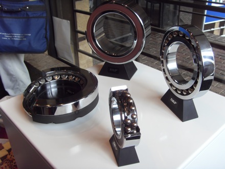
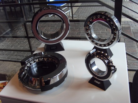
The bearings illustrated below represent a small set of the huge variety available, each designed for a specific set of engineering requirements.
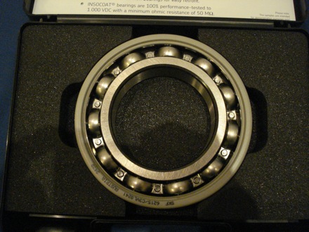
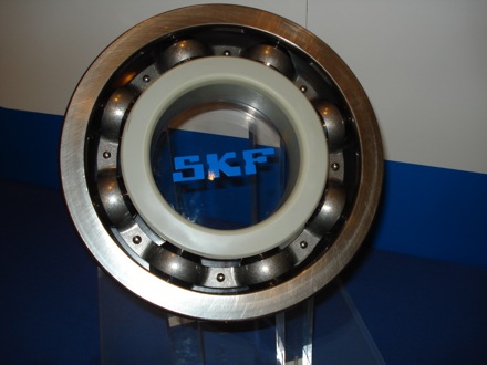
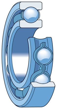
Deep groove bearing
The balls fit well into the deep grooves, enabling the bearing to support axial loads in both directions, in addition to radial loads. The bearing illustrated here has a single row of balls.
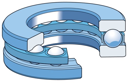
Thrust ball bearing
A thrust ball bearing such as the one illustrated here can support an axial load in one direction. Not designed to accommodate radial loads. The bearing components can easily be separated.
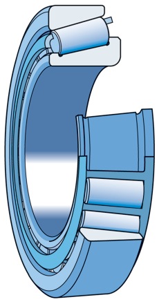
Tapered roller bearing
Both of the rings and the rollers are tapered in order to simultaneously support axial and radial loads. The ratio of the loads supported depends on the angle between the roller and bearing axes. A greater angle helps support a larger axial load.
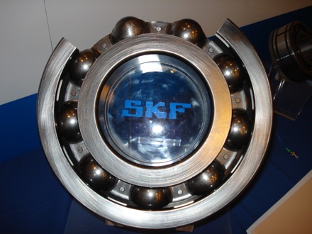
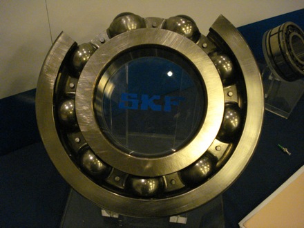
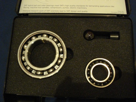
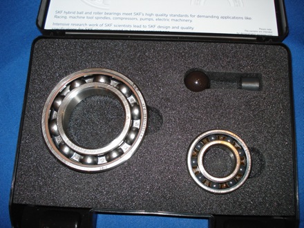
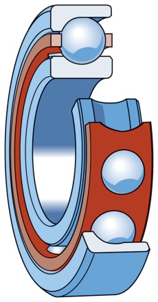
Angular contact ball bearing
This particular design of angular contact ball bearing is able to accommodate a large thrust load in one direction, in addition to radial loads.
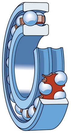
Self-aligning ball bearing
There are two sets of balls which run on a pair of grooves on the inner ring, with a single outer-ring concave surface. This allows the bearing to accommodate misalignment of the shaft.
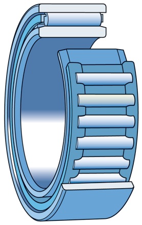
Needle roller bearing
This has long and thin rollers - the design is suited for applications where radial space is limited.
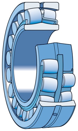
Spherical roller bearing
Because of the angular contact between the rollers and raceways, the bearing is able to accommodate both axial and radial loads; the double set of rollers also permits the bearing to accommodate shaft misalignment. Notice that the rollers are not cylindrical, and hence the adjective `spherical'.
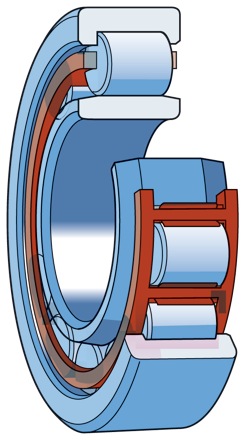
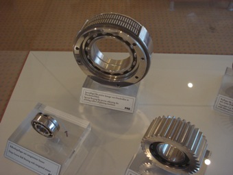
Cylindrical roller bearing
The cylindrical rollers are able to accommodate large radial loads. This is a single-row bearing.
Cylindrical roller bearings played a seminal role in the development of the continuous rolling mill, now used in the manufacture of billions of tonnes of wide-strip steel (Aylen, 2010). Prior to this, the rolling process was by repeatedly passing the steel through a single mill, involving many steps of handling and heating. The original bearing design had an outer forged steel ring and a fixed bronze-bearing race holding steel rollers in position. Modern bearings of this kind would be made entirely of steel.
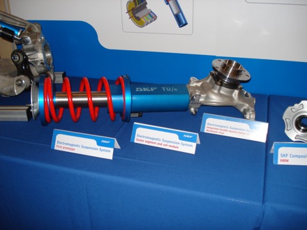
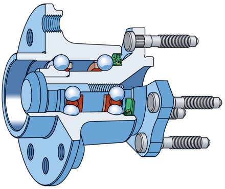
Wheel hub bearing
Large numbers of these bearings are manufactured annually to satisfy demand particularly from the automotive industries. Such bearings obviously support the radial load due to the weight of the automobile, but also thrust loads arising when the motion of the vehicle is not strictly linear.
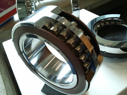
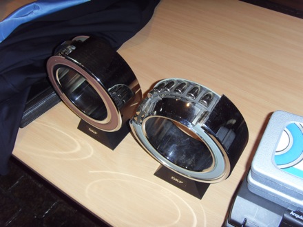
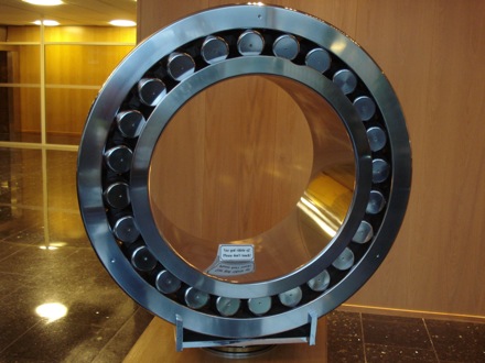
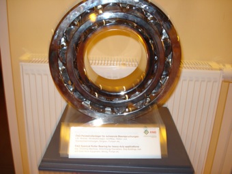
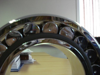
This spherical roller bearing is about a metre in diameter
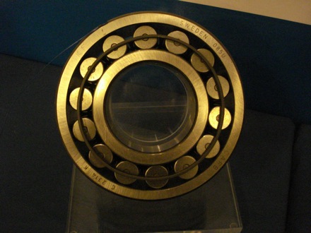
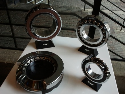
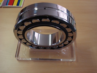
Spherical roller bearings
This is a spherical roller bearing. Roller bearings use cylinders instead of balls and have a greater load bearing capacity because of the greater contact between the rolling element and the rings. A spherical--roller bearing uses barrelled cylinders as the rolling elements, with two sets of rollers enclosed by the rings. This allows the bearing to accommodate a misaligned load.
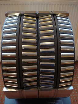
This is a tapered roller bearing. Taper roller bearings take this concept of increasing contact area further by making the rings and rollers tapered, to increase the contact area, permitting large radial and thrust loads.
Notice that the ring sections are tapered
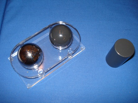
Breakfast
In a deep groove roller bearing, the spherical balls sit within a somewhat matching groove
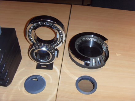
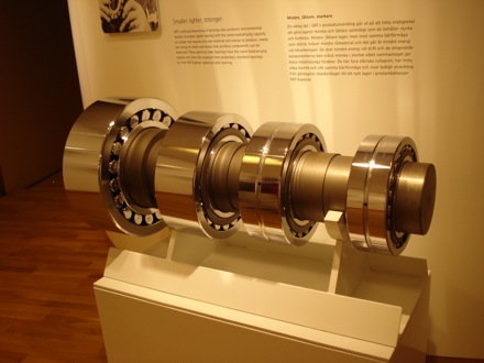
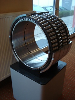
Spherical roller bearing; the black ring that holds the rollers in place is made of mild steel.
Spherical roller bearing; 25 cm diameter.
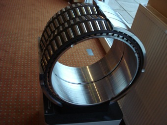
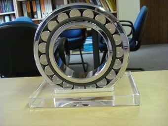
Spherical roller bearing; two sets of rollers to accommodate axial misalignment.
Spherical roller bearing; displayed in Harry's office
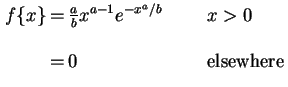
When a large number of measurements are made of the lifetime of a component and a distribution is plotted, the probability of small or long lives is generally small, with the distribution peaking somewhere in between, Fig. 1a. A Weibull probability density function has the form
(1)
where
and
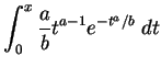
are positive constants. The cumulative probability distribution is obtained by integrating this
(2)
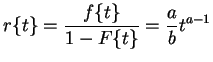
Associated with each such distribution is a
failure rate function, where
represents the probability of failure during a time interval
for a component which has survived to the time
. Objects that have survived longer would in general be expected to have a higher probability of failure [1]:
(3)
For values of
, the form of the Weibull distribution is akin to that of the gamma distribution, but with the important difference that unlike the gamma distribution, the failure rate function does not have an upper bound. (Fig. 1a). Real components after all do not have a well-defined upper bound life.
The versatility of the Weibull distribution to take on the characteristics of other types of distributions is illustrated by setting
, in which case the distribution takes the form of an exponential, with a constant failure rate function, Fig. 1. A constant failure rate is unusual but might arise in special cases where there is regular maintenance.
Figure 1:Weibull distributions. (a) With
and
. (b) with
and
.
(a)
(b)
Equation 2 is sometimes written with an additional parameter as follows:
(4)
where
is known as the Weibull modulus; a large value of
narrows the distribution and hence gives greater consistency in the parameter being tested or modelled. The additional parameter
can be taken as a minimum value of
and can be set to zero.
locates the distribution and is an empirical constant. In using this last equation, care must be taken to respect units and whether the logarithms are natural or to base 10.


![\includegraphics[width=0.45\textwidth]{Weibull.eps}](./Weibull/img15.png) (b)
(b)
![\includegraphics[width=0.45\textwidth]{Weibull_exp.eps}](./Weibull/img16.png)