

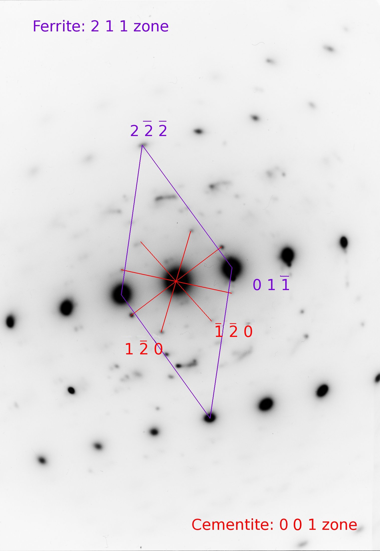
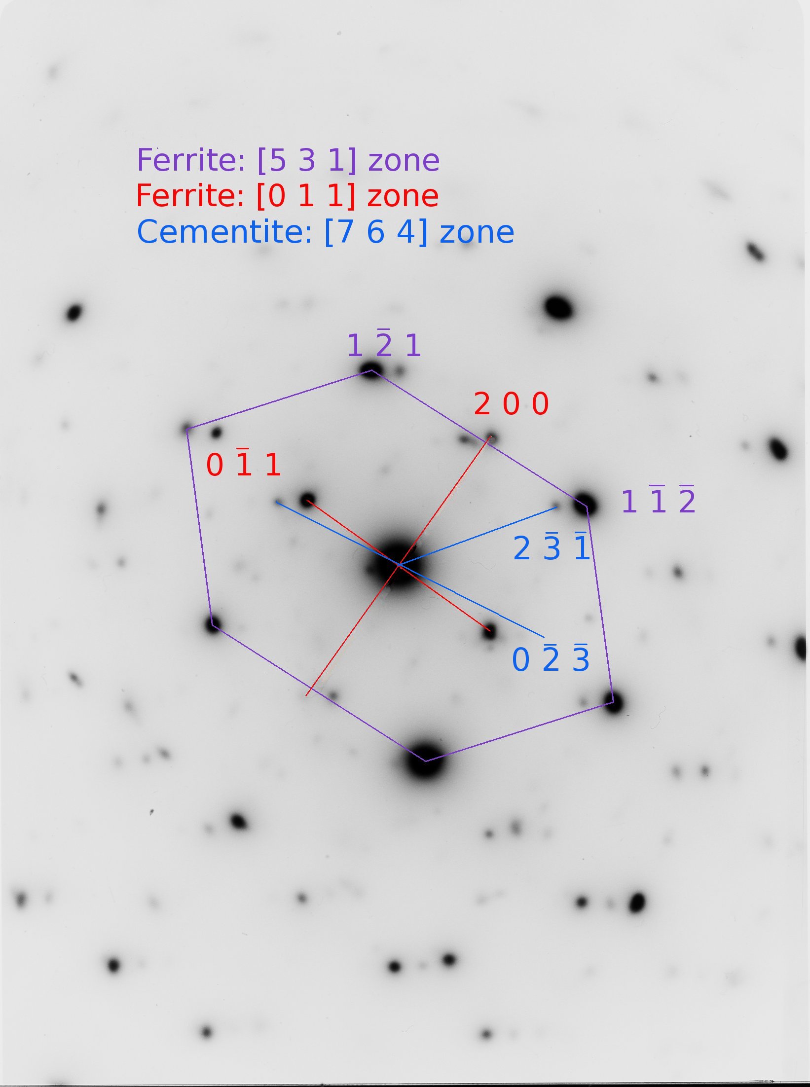
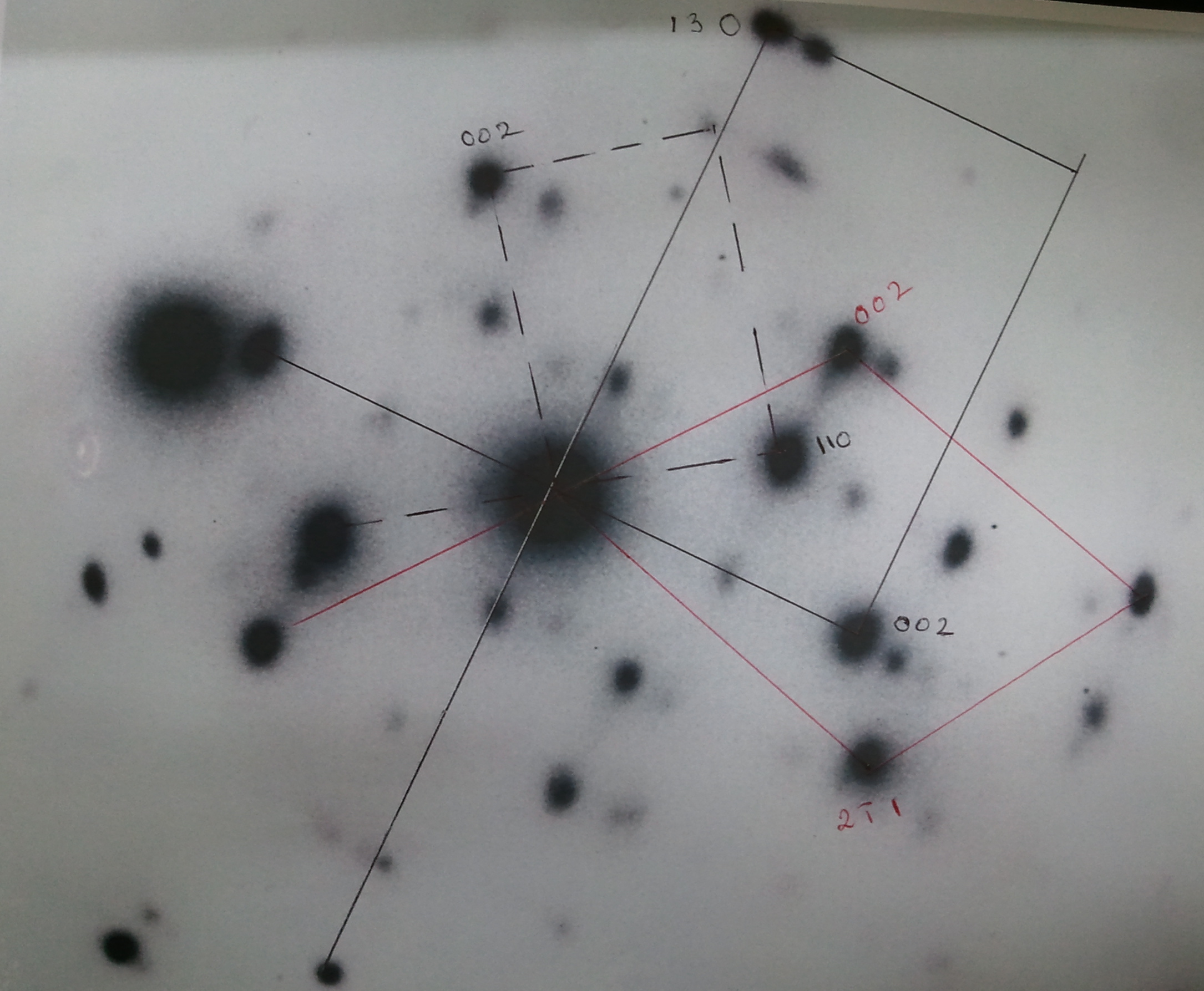
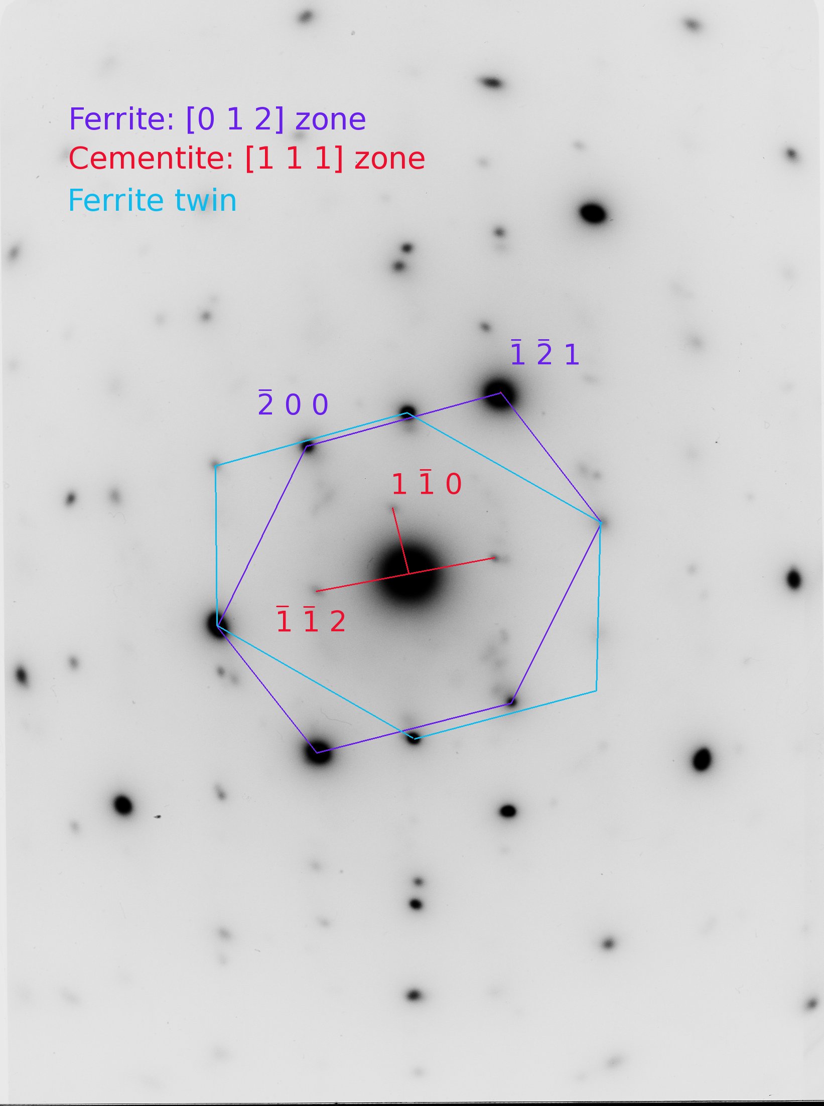
The crystallographic properties and diffraction analysis of various iron phases, specifically focusing on austenite and ferrite, is addressed. This includes the use of X-ray and electron diffraction to identify complex structures and the spatial relationships between iron and cementite precipitates. The documentation details the following microstructural and experimental characteristics:
Overall, the material serves as a technical guide for understanding the atomic arrangements and phase identification in steel through precise crystallographic characterisation.
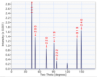
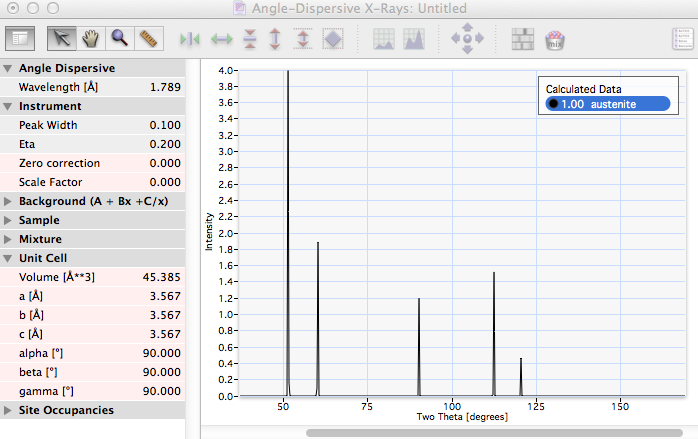
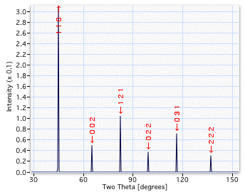
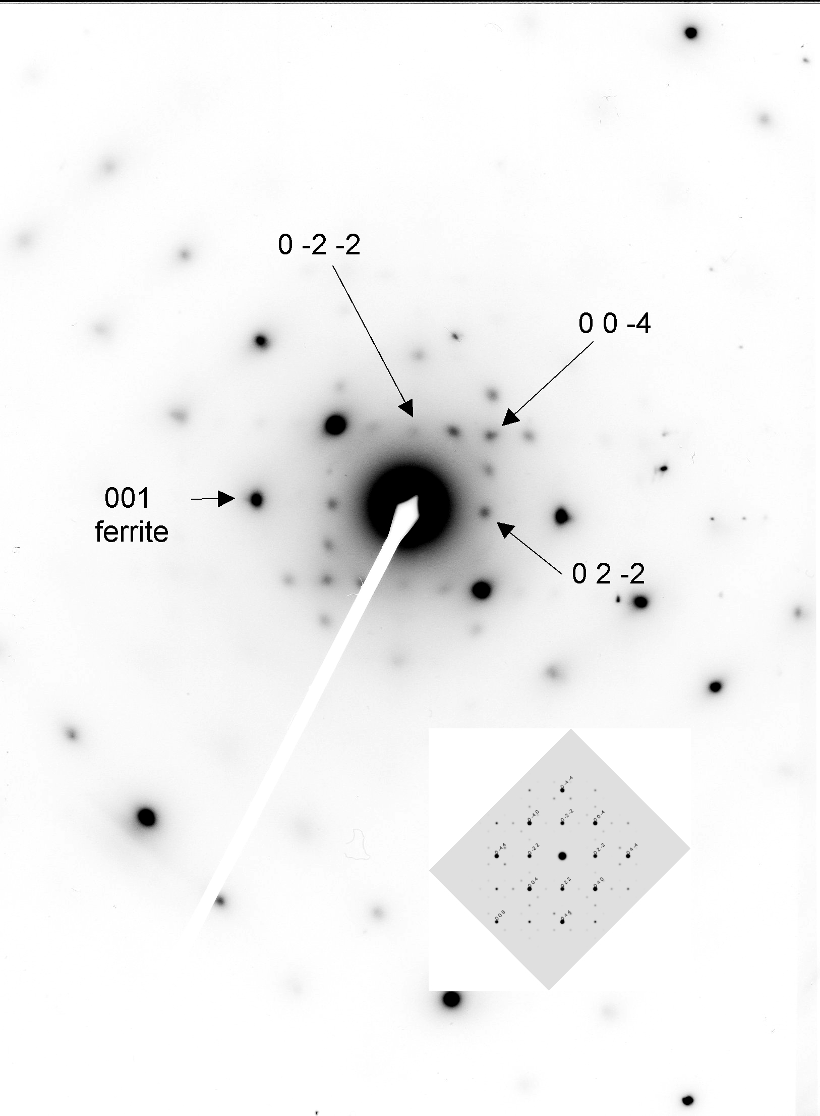
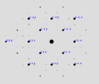
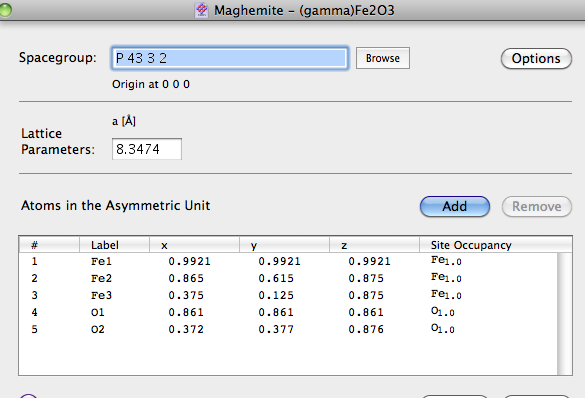
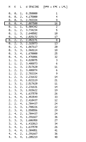
The following details the analysis of complicated electron diffraction patterns containing ferrite, cementite and austenite. A computer programme was utilised to assist in this characterisation.
The following models have kindly been provided by Andrew Fairbank, who engineered them for teaching purposes. They are reproduced with permission.
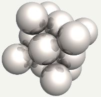
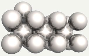
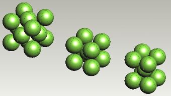 Face-centred cubic, body-centred cubic and body-centred tetragonal arrangements of iron atoms.
|
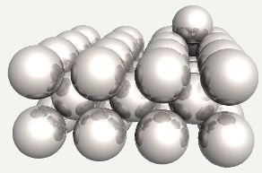
 Face-centred cubic, body-centred cubic and body-centred tetragonal arrangements of iron atoms.
|
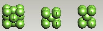
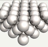
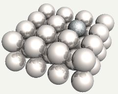
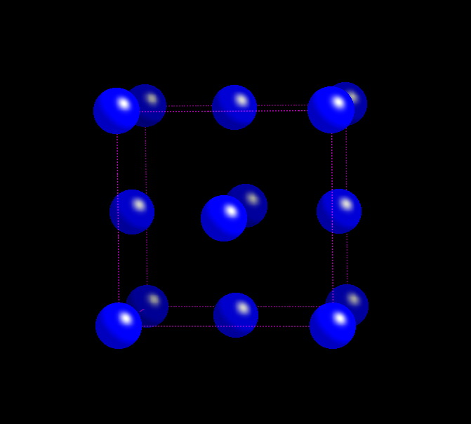
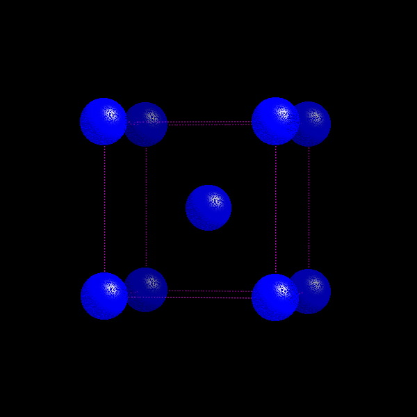
 Body-centred cubic and face-centred cubic (alternatively, cubic close-packed) arrangements of iron atoms.
|
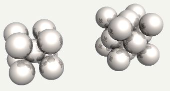
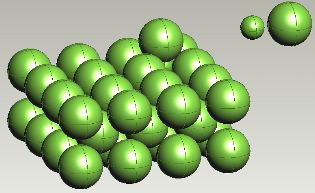
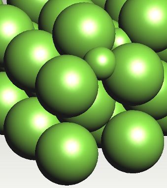
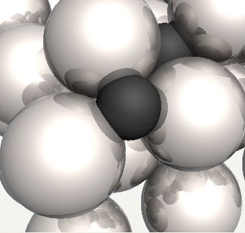
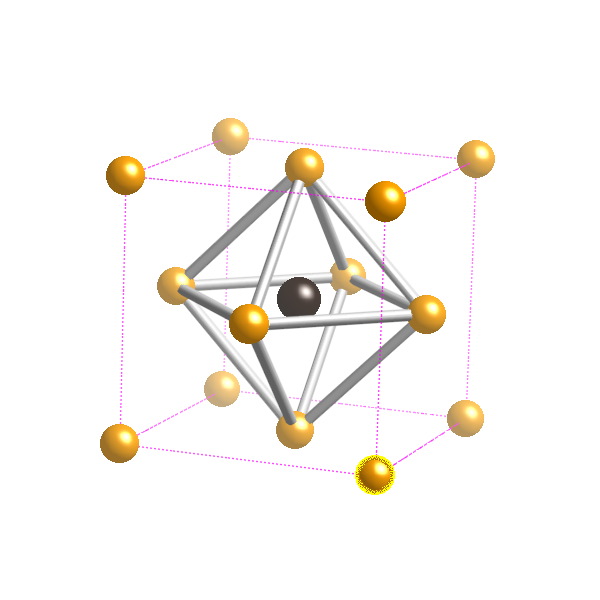
 Carbon atom in an octahedral interstice in austenite.
|
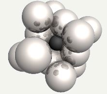
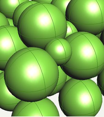
 Carbon atom in an octahedral interstice in austenite, with the face-centering iron atom replaced into position.
|
 Carbon atom in an octahedral interstice in austenite.
|
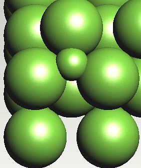
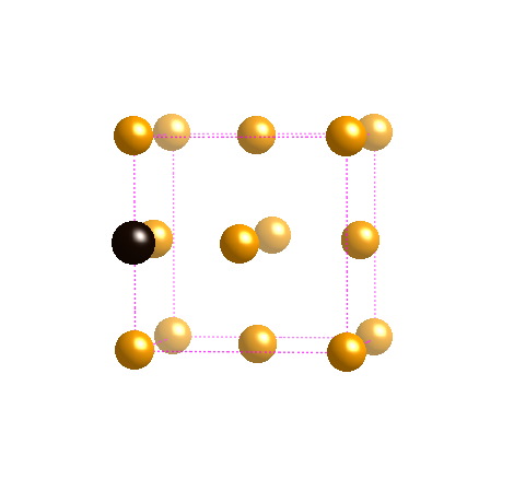
 Carbon atom in an octahedral interstice in ferrite.
|
 Carbon atom in an octahedral interstice in ferrite.
|
 Carbon atom in an octahedral interstice in ferrite.
|
|
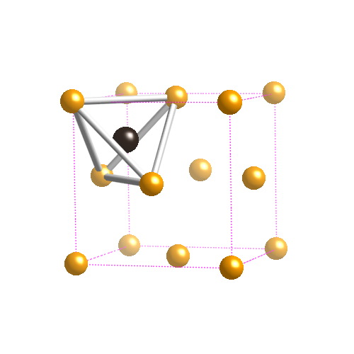
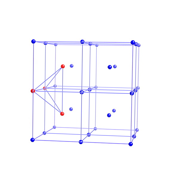
 Possible position of a carbon atom in a tetrahedral interstice in ferrite. Carbon preferred configurations tracks to the octahedral interstices in ferrite.
|
 Possible position of a carbon atom in a tetrahedral interstice in ferrite.
|
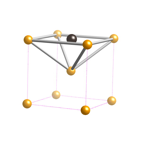
 Possible position of a carbon atom in a tetrahedral interstice in ferrite. The strain energy is greater when carbon is in a tetrahedral interstice, because the expansion is isotropic, unlike the octahedral case where the strain is tetragonal.
|
 Possible position of a carbon atom in a tetrahedral interstice in ferrite.
|
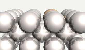 Chromium atom substituted into ferrite.
|
 Chromium atom substituted into ferrite.
|
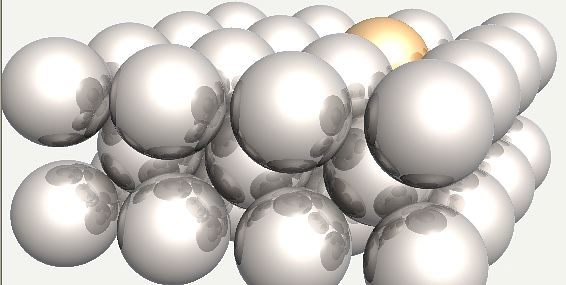
 Silicon atom substituted into ferrite.
|
 Atomic radii. It has been assumed in the preceding figures that iron has an atomic radius of 124 pm for all crystal structures.
|


