Possible Effects of Stress on Steel Weld Microstructures, Mathematical Modelling of Weld Phenomena 2, pp. 71-118, by H. K. D. H. Bhadeshia, Eds. H. Cerjak and H. Bhadeshia, Institute of Materials, London (1995)

|
|
Possible Effects of Stress on Steel Weld Microstructures, Mathematical Modelling of Weld Phenomena 2, pp. 71-118, by H. K. D. H. Bhadeshia, Eds. H. Cerjak and H. Bhadeshia, Institute of Materials, London (1995) |
Mathematical Modelling of Weld Pheonomena 2, eds H. Cerjak and H. K. D. H. Bhadeshia, Institute of Materials, London, 1995, pp. 71-118.
H. K. D. H. Bhadeshia
University of Cambridge
Materials Science and Metallurgy
Pembroke Street, Cambridge CB2 3QZ, U. K.
www.phase-trans.msm.cam.ac.uk
Little is known about the effect of stress on the development of microstructure in steel welds. This paper contains an assessment of published data together with a description of the theory that is available for dealing with stress-affected transformations in steels. Attention is focused on those transformations which have the greatest potential for interaction with an externally applied stress. These include the solid-state transformation products of austenite, such as Widmanstätten ferrite, acicular ferrite, bainite and martensite.
The ability of an external stress to influence the development of microstructure during solid-state transformation is well established in theory. There is also a great deal of research describing the contrary process, in which phase transformations induce the development of stresses; these are the so-called residual stresses, whose effects are particularly pronounced in constrained assemblies. In fact, residual stresses can arise even in the absence of any phase transformation. All that is required is that the temperature varies with position [1]. It is nevertheless true that experimental observations on steel weldments cannot be fully accounted for without a consideration of the phase changes which occur during the cooling of the weldment to ambient temperature [2,3].
The purpose of the work presented here is to describe the relevance of these concepts to the welding of steels. There is a need for this subject to develop further before serious quantitative applications become viable, although very useful general principles already exist which can help in the assessment of weld phenomena. We therefore consider first the basic principles which are applicable to both the heat-affected zone and fusion zone of a weld, and which are useful in phase transformation theory per se.
The familiar mechanisms of plastic deformation are slip, mechanical twinning and diffusion-induced creep. For very small plastic strains, the first two of these deformation modes are conservative - i.e., they preserve an atomic correspondence between the deformed and undeformed parts of the crystal so that the crystal contains a memory of its original shape. All of these deformation modes are lattice-invariant because although they cause a change in the shape, the crystal structure remains as it was prior to deformation.
Phase transformations, by contrast, refer to changes in the crystal structure. However, like lattice-invariant deformations, they can also be associated with changes in the shape of the transformed regions [4-7]. The transformation can have a pronounced interaction with an externally applied stress only if it is accompanied by a shape change (a strain).
In steels, austenite transforms into many varieties of ferrite, which can be classified into two broad categories according to the mechanism of transformation (Fig. 1). Reconstructive transformations occur with the uncoordinated diffusion of all of the atoms, including iron [8,9]. They need not be accompanied by a change in chemical composition, but it is worth emphasising that reconstructive transformations cannot be sustained without the diffusion of all atoms. For example, the freezing of water to ice is a reconstructive transformation where there is mass transport but no change in composition. Similarly, austenite in pure iron can transform into ferrite, either by a reconstructive mechanism involving diffusion, or by a martensitic mechanism. The latter case represents displacive transformations, in which the pattern of atomic arrangement is altered by deformation. There is no diffusion of iron or substitutional solutes during displacive transformations in iron alloys.
![\includegraphics[width=14cm]{classification.eps}](img17.png) |
Both kinds of reactions lead to changes in shape (Fig. 2a). The simplest of these occurs during reconstructive transformations in which the densities of the parent and product phases are different. Hence, when austenite transforms into grain boundary allotriomorphic ferrite, there is a uniform expansion, and vice-versa.
Much more interesting deformations are associated with displacive transformations, where the shape change is in general described as an invariant-pane strain with a large shear component.
Such a deformation leaves the plane of contact between the parent and product phases undistorted and unrotated. This plane is called the habit plane. The strain energy associated with a
constrained invariant-plane strain (IPS) is minimised when the product phase has a thin-plate shape. This is why Widmanstätten ferrite, bainite, acicular ferrite and martensite in steels grow in
the form of plates. The distinguishing features of a variety of deformation modes are compared in Table 1, and the detailed characteristics of the shape change due to transformation are
emphasised in Table 2. The latter also includes some data for mechanical and annealing twins in ferrite and austenite respectively. These are not, of course, transformation products, so that
they do not cause any volume change; however, their growth mechanisms are analogous to those of displacive and reconstructive transformations respectively. The shear component of the IPS for the
mechanical twin is seen to be substantially larger than all of the transformations listed. Indeed, it is only in iron-beryllium alloys (![]() ) that martensitic transformation has a shear strain which is as large as that for mechanical twins in ferrite [10-12]. These empirical observations show that in
general, the shear associated with transformations in steels tends to be smaller than that caused by mechanical twinning.
) that martensitic transformation has a shear strain which is as large as that for mechanical twins in ferrite [10-12]. These empirical observations show that in
general, the shear associated with transformations in steels tends to be smaller than that caused by mechanical twinning.
![\includegraphics[width=12cm]{shape.eps}](img22.png) |
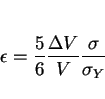
The permanent strain caused by any transformation is called transformation plasticity. A phase change in a stress-free material is usually triggered by heat treatment, when the parent phase passes through an equilibrium transformation temperature. Alternatively, the application of a stress in isothermal conditions can trigger transformation in circumstances where it would not otherwise occur. Unusual effects can occur when stress and temperature work together. The transformation may occur at remarkably low stresses or at very small deviations from the equilibrium temperature. This is why even minute stresses can have a large influence on the development of microstructure. It is not surprising that transformation plasticity can be obtained at stresses which are much smaller than the conventional yield stress of the parent phase.
The plasticity associated with phase transformations has relevance in a wide variety of fields. Some of the important theory of transformation plasticity has its origins in the nuclear industry, where the thermal cycling of uranium through phase changes can lead to large deformations [13,14]. The deformations occur under the influence of very small external stresses, leading to the popular interpretation that there is a mechanical weakening of materials as they undergo a change in crystal structure. Another example of transformation plasticity is when a suicidal virus infects a bacterium with its DNA information. It does this mechanically using a ``hypodermic needle" consisting of a cylindrical crystal. The crystal on transformation changes shape and hence penetrates the bacterium so that the virus can inject the bacterium with its DNA [15]. The virus thus ceases to exist!
A great deal of research followed the exploitation of transformation plasticity in TRIP steels [16], which are designed to make a propagating crack do work in stimulating transformation [17-25]. This greatly increases the work of fracture. Recent applications include the design of automobile steels containing retained austenite, which transforms and plasticises the steel during the forming process [18,19]. The research on TRIP steels has led to one of the few promising mechanisms for the toughening of ceramics [20-22]. The subject of transformation plasticity is of fundamental interest [17,23-27] and of use in the design of heat-treatments [28-32].
As far as welds are concerned, residual stresses in engineering structures can determine the stability and safety of components. There is considerable activity in the experimental determination of these stresses and on computation methods which include a role of transformation plasticity in the development of residual stresses [2,3,33,34].
Since the classical papers by Greenwood and Johnson [13,14], the way in which transformation plasticity is included in the solution of engineering problems has focused on the role of the volume
change. For a longitudinal stress ![]() , Greenwood and Johnson found that the longitudinal plastic strain is given
by:
, Greenwood and Johnson found that the longitudinal plastic strain is given
by:
 |
(1) |
It is common, during discussions of slip, to refer to the crystallographic indices of the slip plane and direction. We have seen that a reconstructive transformation occurs by diffusion. This diffusion involves the uncoordinated movement of atoms. It is then not possible to relate the combined macroscopic effect of all the atomic motions, to the details of the crystal structure in the manner just described for slip. Deformations caused by reconstructive transformations are more analogous to fluid flow than conservative slip.
The situation is quite different for transformations where there is a coordinated displacement of atoms to achieve the new crystal structure. Just as a combination of a plane and a direction
constitutes a deformation system for slip or twinning, the habit plane and displacement vector of the invariant-plane strain accompanying transformation completely describe the deformation system
responsible for transformation plasticity. The displacement vector describes the sense of the macroscopic displacements accompanying transformation, and along with the habit plane indices, also
contains information about the magnitude of the shear component and dilatational component of the displacements. Typical data for the deformation systems associated with transformations are listed in
Table 3.
Given the cubic crystal structure, and the fact that habit planes tend to be irrational, there will in general be 24 of these systems per austenite grain, and they may operate simultaneously to varying extents. Of course, unlike ordinary slip, the different deformation systems within an austenite grain cannot intersect, except in special circumstances where inter-variant transformations are possible, as is the case with some shape memory alloys. It follows that the ordinary notion of work hardening does not apply. Work hardening nevertheless manifests itself via a different mechanism, in which the stability of the austenite increases as it becomes ever more finely divided.
The Taylor/von Mises criterion [46,47] states that in any given crystal, a minimum of five independent slip systems are necessary to produce an arbitrary shape change. A crystal in a polycrystalline aggregate has to accommodate the arbitrary deformations of neighbouring grains. Therefore, a polycrystalline material is brittle unless each grain contains at least five independent slip systems. Similar logic can be applied to the crystallographic variants of a phase generated by displacive transformation. The habit plane is predicted theoretically [48,49] and found experimentally [50] to have irrational indices. This means that there exist in principle, 24 possible variants of the habit plane per grain of austenite (i.e., 24 independent deformation systems). Given this large number of transformation variants available per grain, the Taylor criterion leads to the conclusion that transformation plasticity can cause, or accommodate any externally imposed, arbitrary shape change assuming that a sufficient quantity of parent phase is available. It follows that polycrystalline samples can remain intact at grain boundaries when transformation plasticity is the sole mode of deformation.
The interaction of an externally applied stress (which is below the yield strength of the parent phase) can manifest in two ways:
Both of these factors are illustrated in Fig. 3, where a fine grained polycrystalline sample of austenite was stressed at a temperature above its
normal martensite-start temperature [51]. The amount of martensite obtained is seen to vary directly with the magnitude of the applied stress. The stress manifests as a mechanical driving force whose
contribution assists the chemical driving force, which on its own is inadequate to trigger transformation. Not only does the stress induce the formation of martensite, but only those variants which
comply with the tensile stress grow in profusion (FIg. 3b). Thus, most of the plates are tempted to grow on those planes which are close to the plane of
maximum shear stress (45![]() to the tensile axis). The microstructure would have been much more chaotic in the
absence of the stress. The stress caused the alignment of plates, and a more ordered, organised microstructure.
to the tensile axis). The microstructure would have been much more chaotic in the
absence of the stress. The stress caused the alignment of plates, and a more ordered, organised microstructure.
![\includegraphics[width=12cm]{burst.eps}](img31.png) |
These considerations are dependent on the mechanism of transformation. For reconstructive transformations, it is only the hydrostatic component of stress that can interact with the shape change (which is due to just a density change). The response to an arbitrary stress is therefore not expected to be as large as that for displacive transformations in steels. In that case, the shear component of the IPS is relatively large and so is the corresponding mechanical driving force component.
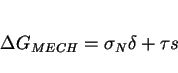
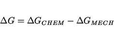
We now focus on displacive transformations, using a method which is based on Patel and Cohen's work [52]. In the above discussion, the total driving force was partitioned implicitly into a ``mechanical driving force" and the more familiar chemical driving force [26,52]. This is based on the reasoning that the movement of a glissile interface is a combined deformation and transformation process. The work done by the external stress may be added to the chemical free energy change in order to obtain the net free energy difference.
The mechanical driving force is assumed to be given as the work done ( ![]() ) by the external stress in producing the macroscopic shape deformation:
) by the external stress in producing the macroscopic shape deformation:
 |
(2) |
![\includegraphics[width=12cm]{resolve.eps}](img35.png) |
It follows from the Patel and Cohen analysis, that since the shear stress remains positive irrespective of whether the sample is pulled in tension or uniaxially compressed, and since the shear component of the shape change is large, a uniaxial stress will always cause an increase in the temperature for displacive transformations in steels. Hydrostatic stress, on the other hand, has no deviatoric components and consequently only interacts with the dilatational component of the shape change. Thus, hydrostatic compression is expected and found to lead to a decrease in the transformation temperature (Fig. 5); some data [27] on the sensitivity of the transformation temperature to applied stress are presented in Table 5.
![\includegraphics[width=12cm]{patel.eps}](img41.png) |
A reservation to the methodology described above is that shear stresses, unlike pressures, can not strictly be considered as state variables so that their use in thermodynamic equations can be uncertain [26]. This difficulty is, however, unimportant in the analysis as long as irreversible processes, such as diffusion or the multiplication of dislocations, do not act to relieve any of the shear stresses during the interval in which the experiment is conducted. What this means in practice is that in the absence of transformation, the state of the system is not altered if the shear stress is changed and then restored to its original value.
A second complicating factor could arise if the stress influences the very nature of the transformation product, either by stimulating the formation of some metastable phase, or by decoupling groups of self-accommodating variants which would form in the absence of stress [26]. This could lead to a large modification of the chemical driving force term. As discussed later, there is some evidence to show that there are significant microstructural changes when bainite, acicular ferrite or martensite grow under the influence of an externally applied stress. Similar effects are expected for Widmanstätten ferrite (and carbides which occur at low temperatures) but they have not yet been confirmed experimentally.
Assuming that the interaction of the applied stress is with the macroscopic shape deformation, the stress must tend to favour the growth of those particular variants for which ![]() is maximised. Hence, for a tensile stress, plates which have their habit planes inclined at
approximately 45
is maximised. Hence, for a tensile stress, plates which have their habit planes inclined at
approximately 45![]() to the tensile axis will tend to be favoured. The angle will not be exactly
to the tensile axis will tend to be favoured. The angle will not be exactly ![]() because the displacement vector of the IPS is not quite parallel to the habit plane whenever there is a volume change
accompanying transformation.
because the displacement vector of the IPS is not quite parallel to the habit plane whenever there is a volume change
accompanying transformation.
This assumes that the applied stress interacts only with the growth process. Its interaction with nucleation events could lead to a different criterion for variant selection [26]. Indeed, efforts at predicting the martensitic transformation texture from the crystallographic texture of the parent austenite, are apparently more successful if it is assumed that variant selection depends on the Bain strain rather than on the macroscopic shape deformation [54]. The IPS deformation is unlikely to have developed at the nucleation stage, where the particle might be too small to sustain the lattice-invariant deformation that is necessary to convert the effects of the lattice deformation into what is macroscopically an invariant-plane strain. On the other hand, since the Bain strain is necessary to accomplish the lattice change, the texture prediction work indicates that variant selection may depend on the interaction of the applied stress with the nucleation process.
At temperatures close to that at which the equilibrium transformation occurs, an applied stress can assist reaction when the chemical driving force is insufficient to achieve the change on its own. There must exist a point, however, when the applied stress simply cannot provide enough mechanical driving force to complement the chemical term to give a driving force large enough to induce transformation. After all, the magnitude of the stress that can be applied is limited by the yield point of the parent phase. There are, therefore, limits to what can be achieved by the application of stress as a stimulus to transformation (Fig: 6). In fact, work hardening may also limit the influence of stress, since transformation can actually be retarded by plastically deforming the parent phase. This is known as mechanical stabilisation.
![\includegraphics[width=12cm]{driving.eps}](img48.png) |
The highest temperature at which martensite forms during the cooling of austenite is the ![]() temperature.
This can be raised by the application of a suitable stress [52]. The maximum temperature at which martensite grows under the influence of stress is called the
temperature.
This can be raised by the application of a suitable stress [52]. The maximum temperature at which martensite grows under the influence of stress is called the ![]() temperature [55]. These phenomena are also revealed by studying the tensile strength of a sample containing austenite ([44], Fig: 7). At first the stress assists martensite formation so that the sample deforms readily. The formation of martensite at increasing temperatures above
temperature [55]. These phenomena are also revealed by studying the tensile strength of a sample containing austenite ([44], Fig: 7). At first the stress assists martensite formation so that the sample deforms readily. The formation of martensite at increasing temperatures above ![]() becomes more difficult so that the strength rises towards that of austenite. Eventually, at
becomes more difficult so that the strength rises towards that of austenite. Eventually, at ![]() the austenite begins to yield by slip. Finally, transformation becomes impossible above
the austenite begins to yield by slip. Finally, transformation becomes impossible above ![]() .
.
There are no similar experiments for the other transformation products, but it is possible to piece together a lot of circumstantial evidence to show that the behaviour of bainite is probably similar to that of martensite.
Goodenow et al. [56] showed that the transformation stresses associated with the growth of lower bainite stimulated the growth of upper bainite at temperatures just above ![]() , showing that stress can indeed raise the bainite-start temperature. It should in principle be possible to define a
, showing that stress can indeed raise the bainite-start temperature. It should in principle be possible to define a ![]() temperature. Early work by Cottrell [57] gives some support to the
temperature. Early work by Cottrell [57] gives some support to the ![]() concept. He found that the maximum volume fraction of bainite obtainable by isothermal transformation of unstressed samples, can be increased with the
application of a tensile stress during transformation, but that the effect of the applied stress diminished as the bainite-start temperature was approached. Drozdov et al. [58] demonstrated
that at a high enough transformation temperature above
concept. He found that the maximum volume fraction of bainite obtainable by isothermal transformation of unstressed samples, can be increased with the
application of a tensile stress during transformation, but that the effect of the applied stress diminished as the bainite-start temperature was approached. Drozdov et al. [58] demonstrated
that at a high enough transformation temperature above ![]() (at which the austenite is still metastable), no
amount of deformation causes the austenite to transform to bainite, a result which can be interpreted easily if it is assumed that the temperature concerned was higher than
(at which the austenite is still metastable), no
amount of deformation causes the austenite to transform to bainite, a result which can be interpreted easily if it is assumed that the temperature concerned was higher than ![]() .
.
These concepts are illustrated schematically in Fig: 8, which illustrates bainite but is based on similar ideas for martensitic transformations; the
details have yet to be established systematically for bainite or other displacive transformation products. The net driving force available for transformation, ![]() , is given by:
, is given by:
 |
(3) |
It is convenient to define a temperature ![]() , beyond which the austenite can no longer elastically support the applied stress prior to
transformation. Clearly, beyond
, beyond which the austenite can no longer elastically support the applied stress prior to
transformation. Clearly, beyond ![]() , the notion of using
, the notion of using ![]() in the thermodynamic equations becomes highly dubious since the austenite inevitably undergoes plastic deformation prior to transformation. The deformation induced defects might then
influence the progress of transformation, perhaps by providing additional nucleation sites, although this kind of stimulation does not seem prominent in bainitic transformations where the predominant
site for sheaf nucleation is almost always an austenite grain boundary. Following the terminology established for martensitic transformations, the region below
in the thermodynamic equations becomes highly dubious since the austenite inevitably undergoes plastic deformation prior to transformation. The deformation induced defects might then
influence the progress of transformation, perhaps by providing additional nucleation sites, although this kind of stimulation does not seem prominent in bainitic transformations where the predominant
site for sheaf nucleation is almost always an austenite grain boundary. Following the terminology established for martensitic transformations, the region below ![]() is said to represent stress-assisted transformation, whereas strain-induced
transformation describes the regime where the yield stress of the parent phase is exceeded.
is said to represent stress-assisted transformation, whereas strain-induced
transformation describes the regime where the yield stress of the parent phase is exceeded.
As the stress is increased further, beyond the yield stress of the austenite, the bainite-start temperature continues to rise. When the ![]() temperature
temperature ![]() is reached,
the chemical driving force actually opposes transformation so that the mechanical component has to be larger than
is reached,
the chemical driving force actually opposes transformation so that the mechanical component has to be larger than ![]() at
at ![]() . Of
course, as the temperature rises, the yield stress of the austenite decreases, until it is no longer able to support a stress large enough to stimulate bainitic transformation; that temperature
corresponds to
. Of
course, as the temperature rises, the yield stress of the austenite decreases, until it is no longer able to support a stress large enough to stimulate bainitic transformation; that temperature
corresponds to ![]() (Fig. 8).
(Fig. 8).
The effects of stress on martensitic transformations have been researched extensively, especially in the context of the shape memory effect [55]. Because the data on other higher temperature transformations are much more limited, but nevertheless important in welding, it is worth discussing how general observations on the next best researched transformation product (bainite) can give confidence in the interpretation that all of the displacive transformations of interest.
It is well known in the context of thermomechanical processing, that deformation accelerates the rate of the bainite reaction [57-63]. There is also good evidence that the rate of reaction under stress increases with the rate of deformation [58,63]. The degree of transformation to bainitic ferrite at any temperature is limited by the incomplete reaction phenomenon [9], but the application of a tensile stress during transformation has been shown to stimulate further reaction beyond the limiting value [57]. The rate of reaction is also found to accelerate under the influence of a tensile stress as long as the stress exceeds a threshold value whose magnitude decreases with increasing temperature, although the significance of the threshold stress is not clear [64]. Umemoto et al. [65] have demonstrated an acceleration of transformation even when the applied tensile stress was rather small (Fig: 9).
![\includegraphics[width=12cm]{overall.eps}](img63.png) |
The stress influencing transformation need not be applied externally; internal stresses generated due to other transformations also have an effect. Early studies indicated an acceleration in the
rate at which upper bainite forms in specimens which are first transformed partially at a lower temperature [66,67]. Martensite is the first phase to form on cooling a steel below the ![]() temperature, but after the initial burst of martensitic transformation and a suitable incubation period, the austenite
undergoes accelerated decomposition to bainite [68]. This is because the austenite is deformed by the martensitic transformation. Supporting evidence is found in magnetometric studies, which have
revealed that isothermal reaction below the
temperature, but after the initial burst of martensitic transformation and a suitable incubation period, the austenite
undergoes accelerated decomposition to bainite [68]. This is because the austenite is deformed by the martensitic transformation. Supporting evidence is found in magnetometric studies, which have
revealed that isothermal reaction below the ![]() temperature leads first to the formation of the usual athermal
martensite, followed by a small amount of isothermal martensite, and then some of the residual austenite begins to transform at an accelerated rate to bainite [69]. Similar results have been obtained
by Radcliffe and Rollason [70] and it has also been demonstrated that the upper bainite reaction is accelerated by initial partial (displacive) transformation to lower bainite (Fig: 10). Their experiments also clearly illustrate the ``flat tops" of the bainite C-curves as highlighted first by Zener [71].
temperature leads first to the formation of the usual athermal
martensite, followed by a small amount of isothermal martensite, and then some of the residual austenite begins to transform at an accelerated rate to bainite [69]. Similar results have been obtained
by Radcliffe and Rollason [70] and it has also been demonstrated that the upper bainite reaction is accelerated by initial partial (displacive) transformation to lower bainite (Fig: 10). Their experiments also clearly illustrate the ``flat tops" of the bainite C-curves as highlighted first by Zener [71].
Another revealing observation is that both the nucleation and growth rates of bainite are accelerated by the proximity of a free surface [72,73]. This observation emphasises the role of the shape deformation of bainite, since any shape change can be accommodated better at a free surface, where the degree of physical constraint is smaller. In the absence of such mitigating circumstances, the matrix sometimes cannot tolerate the large displacements associated with the formation of bainite. It then relaxes by plastic deformation, which is driven by the shape change due to transformation [74].
![\includegraphics[width=12cm]{internal.eps}](img64.png) |
Deformation does not always accelerate transformation; it is well established for martensitic transformations that severe deformation causes the mechanical stabilisation of the austenite. Mechanical stabilisation is due to the work hardening of the austenite as its defect density increases. The defects interfere with the motion of glissile transformation interfaces.
There are no systematic studies of mechanical stabilisation for bainitic or other elevated temperature reactions. It has been reported that during the continuous cooling transformation of a low-alloy steel into a mixed microstructure, the decomposition of austenite to bainite was retarded when the austenite was deformed prior to transformation [75]. This could be interpreted as mechanical stabilisation, but there is unfortunately an alternative explanation for these particular experiments, an explanation which is consistent with the reported data. The deformation accelerates the formation of allotriomorphic ferrite, thereby causing an exaggerated enrichment of the residual austenite with carbon, and therefore a retardation of both the bainite and martensite reactions.
Better evidence comes from experiments using hot-rolled samples, which have demonstrated that the austenite which is deformed to a larger extent, tends to transform to bainite at a lower temperature during continuous cooling (Fig: 11). This effect can only be interpreted in terms of mechanical stabilisation because the alloy used had sufficient hardenability to avoid the growth of allotriomorphic ferrite or other interfering transformation products during cooling.
![\includegraphics[width=12cm]{davenport.eps}](img65.png) |
Perhaps the most convincing evidence for the mechanical stabilisation of bainite comes from studies of ausformed bainite. Samples of deformed austenite gave smaller maximum volume fractions of bainitic ferrite when compared with those transformed without any prior deformation. This is in spite of the fact that the deformed austenite transformed initially at a higher rate (Fig. 11). This effect did not appear during transformation at higher temperatures, presumably because the total volume fraction of bainite that can form is then reduced. Stabilisation therefore only manifests itself when the ``easy" regions of austenite are exhausted, i.e., those regions left unchanged by the inhomogeneous deformation. The nonuniformity of stabilisation is reflected in the microstructure that develops. The sheaves of bainite that do form are found to be aligned along specific directions within individual austenite grains, in contrast with the usual bainitic transformation where sheaves grow in many different orientations (Fig: 12).
![\includegraphics[width=12cm]{ausform.eps}](img66.png) |
As is often the case with martensite plates in ausformed alloys, sheaves of bainite are sometimes found to be curved on a macroscopic scale. This is because of the deformation induced lattice curvature present in the parent austenite grains prior to transformation (Fig: 16).
Finally, it is worth mentioning two important experiments by Bhattacharyya and Kehl [77]. They first demonstrated that a tensile stress has little effect on transformation if it is applied after more than about 30% of bainite has formed. The effect was attributed to the fact that the overall strength of the microstructure rises during transformation relative to the applied stress. An alternative explanation could be that it becomes difficult to stimulate variants favoured by the applied stress once many nuclei have been activated. Any favoured variants that do form will have a limited scope for development as the amount of austenite decreases.
In the second experiment, Bhattacharya and Kehl showed that the removal of stress after some transformation has occurred, does not decrease the rate of reaction. This might suggest that the primary influence of stress is in these experiments to stimulate nucleation rather than growth.
![\includegraphics[width=12cm]{optical.eps}](img67.png) |
There is no doubt that a constrained weld undergoes plastic deformation in its austenitic state, as it cools. The strains involved are of the order of a few percent. Hence, the mechanical stabilisation effects are extremely unlikely. It is not surprising that macroscopically curved plates as discussed above (Fig. 16) are not found in welded samples. The intriguing question is: does the small amount of plastic deformation to be found in the austenite influence the kinetics of transformations as the weld cools? The probable answer is negative, since for martensitic transformations, a small amount of plastic deformation enhances the nucleation rate. However, for the elevated temperature transformations it is unlikely that such dislocations are on their own terribly effective as heterogeneous nucleation sites. For example, allotriomorphic ferrite always nucleates at the austenite grain boundaries, as does bainite and primary Widmanstätten ferrite. Secondary Widmanstätten ferrite grows from allotriomorphic ferrite/austenite surfaces. Acicular ferrite nucleates at inclusions. It is much more likely that in constrained welds the major effects of the stress are via the mechanical driving force and through any changes in the degree of organisation in the microstructure.
An applied stress will tend to favour the development of crystallographic variants which comply with that stress. This is analogous to the selective operation of one or more of the available slip
systems in a crystal under stress; it is the systems with the largest Schmid factors which are favoured. Assuming that variant selection is similarly controlled by the interaction of the applied
stress with the shape deformation, the stress should cause an alignment of the plates at roughly 45![]() to the
tensile axis. This alignment has been observed in many experiments involving transformations in steels including weld deposits [73].
to the
tensile axis. This alignment has been observed in many experiments involving transformations in steels including weld deposits [73].
This is illustrated in Fig. 3 where a fine grained polycrystalline sample of austenite was stressed at a temperature above its martensite-start temperature [51]. The amount of martensite
obtained varies directly with the magnitude of the applied stress (i.e., the mechanical driving force). Not only did the stress induce the formation of martensite, but only those particular
variants of martensite which complied with the applied stress grew in profusion. Thus, most of the plates attempted to grow on planes close to those of the maximum shear stress (approximately 45![]() to the tensile axis).
to the tensile axis).
In the absence of an externally applied stress, each austenite grain could have transformed into one or more of the twenty four possible crystallographic variants, leading to a more chaotic microstructure. The stress caused the alignment of plates, and a more ordered microstructure.
The observations are more difficult for bainite, partly because of the rapid rate of reaction under the influence of stress. The experiments have to be conducted at high temperatures. Further transformation may occur as the sample cools to ambient temperature, confusing the interpretation of the microstructure. Nonetheless, good evidence for microstructural alignment has been reported for bainite platelets especially at relatively large stresses [65,77]. All of these observations are based on polycrystalline samples, but that does not substantially alter the conclusions. There are so many variants available per austenite grain, that there is a high probability of a plate orientation lying close to the optimum with respect to the stress.
There are more subtle effects of stress on microstructure, even in the absence of any obvious plate alignment, at stress levels as small as 45 MPa. Variant selection leads to the development of a less chaotic microstructure [60,62,45]. Without stress, each grain of austenite transforms into many different orientations of bainite. Significantly fewer variants develop per austenite grain under the influence of stress, so that the selected orientations can grow unhindered and form thick packets of bainite plates. The sheaves are therefore found to be longer, and their number density per grain smaller when variant selection operates (Fig: 14).
A further effect on microstructure is when the austenite has been plastically deformed prior to transformation. Heterogeneous nucleation then occurs not only at the original austenite grain boundaries, but apparently also intragranularly on slip bands or other deformation heterogeneities [62].
![\includegraphics[width=12cm]{optical2.eps}](img68.png) |
There is a lot of activity in the steel industry on the subject of ``acicular ferrite", for both welded and wrought alloys. Acicular ferrite is essentially intragranularly nucleated bainite [78]. The heterogeneous nucleation sites are known to be nonmetallic inclusions, either added deliberately, or present as impurities. The microstructures of conventional bainite and acicular ferrite differ significantly: clusters of bainite plates (called sheaves) grow as a series of parallel plates in identical crystallographic orientation emanating from austenite grain surfaces. By contrast, acicular ferrite plates nucleate intragranularly at point sites so that there is no room for parallel formations of plates to develop.
It is believed that the toughness is enhanced when the plates do not form packets, but lie on many differently oriented planes, like acicular ferrite. The feeling is that the latter microstructure causes the cleavage cracks to deflect frequently since a new crystallographic orientation is presented as each plate is encountered.
The dismantling of packets of parallel ferrite plates in bainitic or martensitic microstructures, into more chaotically orientated acicular ferrite plates, improves toughness. The increased chaos can only be achieved by introducing inclusions as intragranular nucleation sites. The greatest success in inducing the formation of acicular ferrite in this way has been achieved in weld deposits, which under normal circumstances contain relatively large concentrations of trace elements such as oxygen (about 300 ppm), aluminium, titanium, etc. introduced during fusion. The gain in toughness achieved in this manner seems to overcome any loss due to the presence of inclusions, in welds and low-strength steels.
It is important in the present context to note that the growth of acicular ferrite causes an invariant-plane strain shape deformation which has a large shear component [79]. And its response to an applied stress is as expected (Fig: 15). The number of variants which form in the presence of a uniaxial stress is reduced considerably, and the transformation strains become correspondingly anisotropic [80].
![\includegraphics[width=12cm]{optical3.eps}](img69.png) |
An interesting observation is that the number of crystallographic variants of acicular ferrite, as found in the as-deposited microstructure of steel welds, is far less than the twenty four that
are theoretically possible in any given austenite grain [80] Fig: ![]() . It
is speculated that this is because of the stresses that develop as the weld cools, so that the growth of acicular ferrite occurs under the influence of some complex stress system. More work is needed
in this area of welding metallurgy.
. It
is speculated that this is because of the stresses that develop as the weld cools, so that the growth of acicular ferrite occurs under the influence of some complex stress system. More work is needed
in this area of welding metallurgy.
![\includegraphics[width=12cm]{optical4.eps}](img70.png) |
There is circumstantial evidence that the carbides which form during the tempering of martensite grow by a displacive mechanism. Such a mechanism must naturally involve the diffusion of carbon,
but not of substitutional solutes or iron atoms. This is consistent with a large amount of data which show that the carbides associated with bainite and martensite do not partition substitutional
solutes during transformation [81-83]. It is particularly interesting that the precipitation of cementite from martensite or lower bainite can occur under conditions where the diffusion rates of iron
and substitutional atoms are incredibly small compared with the rate of precipitation (Fig: 17). The long-range diffusion of carbon atoms is of course
necessary, but because of its interstitial character, substantial diffusion of carbon remains possible even at temperatures as low as -60 ![]() C. Thus, the formation of cementite in these circumstances must differ from the normal reconstructive decomposition reactions, which become sluggish at low temperatures.
It has been believed for some time that the cementite lattice may be generated by the deformation of the ferrite lattice, combined with the necessary diffusion of carbon into the appropriate sites.
The Fe/X ratio thus remains constant everywhere and subject to that constraint, the carbon achieves equality of chemical potential; the cementite is then said to grow by paraequilibrium
transformation [84]. The way in which the ferrite lattice could be deformed to produce the right arrangement of iron atoms needed to generate the cementite has been considered by Andrews [85] and
Hume-Rothery et al. [86], and the subject has been reviewed by Yakel [87]. Further high-resolution evidence supporting the idea that the carbide particles grow by displacive transformation
(involving the diffusion of just carbon) has been published most recently by Sandvik [88], Nakamura and Nagakura [89] and Taylor et al. [90,91].
C. Thus, the formation of cementite in these circumstances must differ from the normal reconstructive decomposition reactions, which become sluggish at low temperatures.
It has been believed for some time that the cementite lattice may be generated by the deformation of the ferrite lattice, combined with the necessary diffusion of carbon into the appropriate sites.
The Fe/X ratio thus remains constant everywhere and subject to that constraint, the carbon achieves equality of chemical potential; the cementite is then said to grow by paraequilibrium
transformation [84]. The way in which the ferrite lattice could be deformed to produce the right arrangement of iron atoms needed to generate the cementite has been considered by Andrews [85] and
Hume-Rothery et al. [86], and the subject has been reviewed by Yakel [87]. Further high-resolution evidence supporting the idea that the carbide particles grow by displacive transformation
(involving the diffusion of just carbon) has been published most recently by Sandvik [88], Nakamura and Nagakura [89] and Taylor et al. [90,91].
![\includegraphics[width=12cm]{diffusion.eps}](img71.png) |
Fig: 18a shows the microstructure obtained after tempering the quenched steel at 300 ![]() C for 30 min, without any externally imposed stress. Most of the martensite plates were found to contain more than one crystallographic variant of
C for 30 min, without any externally imposed stress. Most of the martensite plates were found to contain more than one crystallographic variant of ![]() -carbide particles. These observations confirm the general feeling that a Widmanstätten array of carbides is obtained
when carbon-supersaturated martensite is tempered. However, the number of carbide variants observed is surprisingly small, given that the orientation relationship between
-carbide particles. These observations confirm the general feeling that a Widmanstätten array of carbides is obtained
when carbon-supersaturated martensite is tempered. However, the number of carbide variants observed is surprisingly small, given that the orientation relationship between ![]() -carbide and the matrix is that of Jack [92]. Similarly, given that the ferrite/cementite orientation was always Bagaryatski, the number
of possible variants should be larger than has been observed.
-carbide and the matrix is that of Jack [92]. Similarly, given that the ferrite/cementite orientation was always Bagaryatski, the number
of possible variants should be larger than has been observed.
Recent work by Taylor et al. [91] has shown that the precipitation of transition carbides is influenced by a variety of precursor events. Thus, it is found that the number of carbide
variants that form is less than that expected from an examination of just the crystallography, because precipitation is preceded by spinodal decomposition which causes carbon concentration waves
which are exaggerated along the elastically soft directions of the matrix. The number of these soft directions is limited by the tetragonal symmetry of the martensite lattice. It has been suggested
that the carbides then nucleate and grow by a displacive paraequilibrium mechanism along the carbon-enriched bands. They therefore observed only two carbide variants in any given martensite plate,
even though the plane of precipitation ![]() has a higher crystallographic multiplicity. A further factor which could limit the number of
variants is of course the internal stresses arising due to the shape change of the martensite plates themselves.
has a higher crystallographic multiplicity. A further factor which could limit the number of
variants is of course the internal stresses arising due to the shape change of the martensite plates themselves.
![\includegraphics[width=12cm]{optical5.eps}](img73.png) |
Fig. 18b shows the striking change in carbide precipitation behaviour, caused by tempering the martensite at 300 ![]() C under the influence of a compressive elastic stress of 700 MPa. The vast majority of martensite plates revealed only a single variant of
C under the influence of a compressive elastic stress of 700 MPa. The vast majority of martensite plates revealed only a single variant of
![]() -carbide
-carbide
It is evident that an externally applied stress can reduce the number of variants of carbide particles that precipitate in any given martensite plate. It follows that any internal stresses, due for example to the invariant-plane strain (IPS) shape change accompanying the growth of martensite can have a similar effect. Furthermore, it is now generally accepted that the carbide particles formed during the tempering of martensite probably themselves grow by a displacive transformation mechanism which may involve the diffusion of carbon. This makes it even more probable that the precipitation of carbides should be influenced when it occurs in a stress field.
These results have significant implications on the interpretation of carbide precipitation in lower bainite. The lower bainite grows at relatively high temperatures where the driving force for carbide precipitation from supersaturated ferrite is likely to be smaller than that associated with martensite in the same steel. The chemical driving force will be further reduced since some of the excess carbon can escape into the residual austenite. It is not therefore surprising that there is a tendency to find just one crystallographic variant of carbide in platelets of lower bainitic ferrite.
To summarise, it appears that an externally applied stress can influence the precipitation of carbides in martensite. The number of carbide variants which grow in any given plate of martensite decreases when the virgin martensite is tempered under the influence of the stress. The effect becomes more prominent as the magnitude of the mechanical driving force increases relative to the chemical driving force for carbide precipitation. This explains why lower bainite is usually associated with a single variant of carbide within any individual plate of bainitic ferrite. It is speculated that the results may be of significance in the relief of residual stresses during stress relief heat treatments on welded assemblies.
There is general agreement that the application of hydrostatic pressure causes a retardation of the martensite [94] and bainite [95,96] reactions in steels. The effect on the
time-temperature-transformation diagram is illustrated in Fig: 19. The observed retardation is not in itself a feature unique to displacive reactions. All
transformations which are accompanied by a reduction in density are expected to be retarded by hydrostatic pressure which opposes a volume expansion. The effect of hydrostatic pressure is two fold:
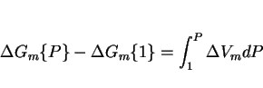
it reduces the diffusion coefficients by decreasing the available free volume (although the details remain to be established), and it influences the free energy change for transformation. If ![]() is the molar Gibbs free energy change for a reaction, then since
is the molar Gibbs free energy change for a reaction, then since
 |
(4) |
 |
(5) |
 |
(6) |
![\includegraphics[width=12cm]{pressure.eps}](img83.png) |
``Microphases" in welds and their heat-affected zones often consist of mixtures of phases such as martensite, carbides and retained austenite. The latter usually has a carbon concentration which is much larger than that of the alloy as a whole, since the carbon is partitioned into the residual austenite during elevated temperature transformations. If this austenite undergoes martensitic transformation induced by stress during welding or during service, then the resulting high carbon martensite is expected to be very brittle indeed. There is in fact a great deal of work in progress throughout the world, dealing with these local brittle zones.
The problem is likely to be most acute in steels where the precipitation of carbides is relatively sluggish, the residual austenite becomes enriched in carbon and a large proportion is retained on cooling to ambient temperature. The austenite, if it decomposes under the influence of stress, can be detrimental to the steel concerned since the resulting high-carbon, untempered martensite is expected to be very brittle. The larger blocky austenite is most likely to decompose to martensite even at relatively small stresses, Fig: 20 [97-102]. The mechanical stability of any retained austenite is therefore important in obtaining good toughness in bainitic steels.
Miihkinen and Edmonds [103-105] have shown that the mechanical stability of the retained austenite decreases as the transformation temperature is increased. This is because the austenite can dissolve less carbon at higher temperatures. Similarly, substitutional solutes which reduce the solubility of carbon in austenite (such as manganese) is likely to make the austenite less stable to stress. The substitutional solute is never added in sufficient quantity to compensate for the loss of austenite stability as its solubility for carbon decreases.
The way to improve local brittle zones consisting of mixtures of austenite and martensite, therefore, is to design alloys in which the solubility of carbon in the austenite is largest. This can easily be achieved using widely available phase diagram computation methods.
![\includegraphics[width=12cm]{optical6.eps}](img84.png) |
Residual stresses are mostly introduced unintentionally during fabrication. They are of particular importance in welded structures which as a consequence become susceptible to hydrogen embrittlement and other detrimental phenomena. Jones and Alberry [106-107] conducted an elegant series of experiments to illustrate the role of transformations in steels, on the development of residual stress.
Using bainitic, martensitic and stable austenitic steels, they demonstrated that transformation plasticity during the cooling of a uniaxially constrained sample from the austenite phase field, acts to relieve the build up of thermal stress as the sample cools. By contrast, the non-transforming austenitic steel exhibited a continuous increase in residual stress with decreasing temperature, as might be expected from the thermal contraction of a constrained sample.
When the steels transformed to bainite or martensite, the transformation strain compensated for any thermal contraction strains that arose during cooling. Significant residual stresses were therefore found to develop only after transformation was completed, and the specimens approached ambient temperature (Fig: 21).
The experiments contain other revealing features. The thermal expansion coefficient of austenite is much larger than that of ferrite, and yet the slope of the line prior to transformation is smaller when compared with that after transformation is completed (Fig. 21). This is because the austenite deforms plastically; its yield strength at high temperatures is reduced so much that the sample is unable to accommodate contraction strains elastically. On the other hand, when ferrite forms, its strength at low temperatures is higher, so that the slope of the stress/temperature curve (after transformation is complete) should be steeper and consistent with the magnitude of thermal contraction strains. All this has yet to be demonstrated quantitatively.
In the region of the stress/temperature curve where transformation happens, the interpretation of experimental data of the kind illustrated in Fig. 21 is very difficult. The predominant view amongst those involved in residual stress calculations, that the volume change during transformation gives the major contribution to transformation plasticity is almost certainly incorrect for displacive transformations such as bainite or martensite. The shape change due to transformation has a shear component which is much larger than the dilatational term. Admittedly, this shear component should on average cancel out in a fine grained polycrystalline sample containing plates in many orientations. However, the very nature of the stress effect is to favour the formation of selected variants in which case, the shear component rapidly begins to dominate the transformation plasticity.
![\includegraphics[width=12cm]{alberry.eps}](img85.png) |
Finally, it is interesting to note that if transformation is completed at a higher temperature, then the ultimate level of stress at ambient temperature is larger, since the fully ferritic sample
contracts over a larger temperature range. To reduce the residual stress level at ambient temperature requires the design of alloys with low transformation temperatures. The sort of high strength
welding alloys used for making submarine hulls tend to have very low transformation temperatures (![]()
![]() C). This fact may be fortuitous, but such alloys should be less susceptible to cracking induced by the development of
residual stresses.
C). This fact may be fortuitous, but such alloys should be less susceptible to cracking induced by the development of
residual stresses.
During their attempts to study the isothermal transformation of austenite using dilatometry, Davenport and Bain [35] had already noticed that ``the volume change (due to transformation) is not necessarily uniformly reflected in linear change in all dimensions". They even found that the thickness of flat disc specimens actually decreased as the volume increased! These results were stated without interpretation; recent work has demonstrated that in polycrystalline samples which are crystallographically textured, anisotropic transformation plasticity can be detected even in the absence of an applied stress [45]. When an unstressed polycrystalline sample of austenite is transformed, the shear components of the individual shape deformations of the large number of variants which form along any dimension should tend to cancel out on a macroscopic scale. Similarly, in the absence of stress, the dilatational component of the IPS shape deformation should tend to average out so that the volume expansion appears to be isotropic. Transformation plasticity (the major component of which comes from the large shear strain of the IPS) should therefore be minimised in a random polycrystalline sample, and due to volume change only. If on the other hand, the sample is not random, i.e., it is crystallographically textured, then the possibility of the individual shape deformations cancelling out over large distances is correspondingly reduced. Transformation will then lead to anisotropic strains even in the absence of any applied stress (Fig: 22).
To summarise, the observed plastic strain will be anisotropic when transformation occurs under the influence of stress. For reconstructive transformations, the maximum amount of plasticity cannot exceed the volume strain, as long as the stress does not exceed the yield strength of the weaker phase. For displacive transformations, the plasticity can be much larger and more anisotropic when the microstructure becomes non-random. For both cases, useful information is to be gained by measuring the transformation strains along more than one direction. Otherwise, for displacive transformations, it is not possible to separate the contributions from volume strain and shear strain. A deconvolution of the observed strain into these components is needed because it is only the volume strain which can be easily related to the extent of transformation in a dilatometric experiment. It is necessary to monitor the extent of transformation because it does not in many cases reach completion.
![\includegraphics[width=10cm]{Oak.eps}](img87.png) |
It has been emphasised that when studying the evolution of microstructure under the influence of stress, it is useful to monitor the strains along more than one direction. The following analysis is for displacive transformations and assumes that the volume strain will be isotropic. Transformation plasticity is therefore attributed solely to the shear strains associated with displacive reactions. This does not follow convention, in the sense that the Greenwood and Johnson (and related methods) deal only with volume change effects. However, the purpose here is to focus on the effects of the shear component of strain due to displacive transformations.
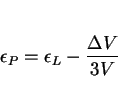
For the case of radial symmetry, the radial and longitudinal strains (![]() and
and ![]() respectively) can be related by [45]:
respectively) can be related by [45]:
 |
(7) |
In fact, the volume change due to the growth of a bainite plate is not isotropic; the dilatational component of the shape deformation is directed normal to the habit plane. However, in a sample
containing many randomly orientated plates of bainite, the overall macroscopic effect of stresses lower than the yield stress of austenite, may still be one in which the volume change appears
isotropic. Furthermore, when the applied stress is larger than the yield stress, the magnitude of the transformation plasticity ![]() becomes much larger than the volume strain. Thus, the effect of any anisotropy in the volume strain becomes negligible by comparison.
becomes much larger than the volume strain. Thus, the effect of any anisotropy in the volume strain becomes negligible by comparison.
Consider a distribution of variants along all radial directions in a circle with the compression axis as its diameter [109]. The circle is divided into eighteen equal segments ( ![]() ), each segment representing a particular orientation of bainite habit plane. The choice of
eighteen segments is convenient and arbitrary. The compression axis of the sample is taken to be the
), each segment representing a particular orientation of bainite habit plane. The choice of
eighteen segments is convenient and arbitrary. The compression axis of the sample is taken to be the ![]() direction, the
direction, the ![]() and
and ![]() directions being radially orientated; the unit vectors
directions being radially orientated; the unit vectors ![]() define the orthonormal basis
define the orthonormal basis ![]() of the sample, giving a corresponding reciprocal basis
of the sample, giving a corresponding reciprocal basis ![]() . The
shear and dilatational components of the invariant-plane strain accompanying the growth of bainite are approximately
. The
shear and dilatational components of the invariant-plane strain accompanying the growth of bainite are approximately ![]() and
and ![]() [9]. Thus, the
[9]. Thus, the ![]() deformation matrix describing the shape deformation is given by [48,49,108-110]:
deformation matrix describing the shape deformation is given by [48,49,108-110]:
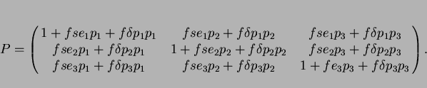 |
(8) |
![\begin{displaymath}P = I + fs \left[\matrix{e_1 \cr e_2 \cr e_3} \right] \left(... ...cr p_2 \cr p_3} \right] \left(\matrix{p_1 ∓ p_2 ∓ p_3}\right) \end{displaymath}](img108.png) |
(9) |
 + f_i\delta[X;\underline p_i](\underline p_i;X^*) \end{displaymath}](img110.png) |
(10) |
The components of the shear direction and the dilatation direction are given by:
![\begin{displaymath}[X; \underline e_i]= f_i [-\cos(\theta_i)~0~\sin(\theta_i)]\end{displaymath}](img112.png) |
(11) |
![\begin{displaymath}[X; \underline p_i]= f_i [\sin(\theta_i)~0~\cos(\theta_i)]\end{displaymath}](img113.png) |
(12) |
A unit vector along the ![]() direction changes to a new vector
direction changes to a new vector ![]() given by:
given by:
![\begin{displaymath}[X;\underline z]= \prod_{i=1}^{18} (X~P_i~X)~ [0~0~1] \end{displaymath}](img118.png) |
(13) |
![\begin{displaymath}[X;\underline x]= \prod_{i=1}^{18} (X~P_i~X)~ [1~0~0] \end{displaymath}](img120.png) |
(14) |
It is expected that those segments which comply best with the applied stress transform most rapidly, whereas the others do so at a smaller rate, or not at all. This can to some extent be
incorporated into the model by calculating the energy change ![]() as the stress interacts with the shape deformation
of a particular variant (
as the stress interacts with the shape deformation
of a particular variant (![]() ). Patel and Cohen's method [52] gives:
). Patel and Cohen's method [52] gives:
![\begin{displaymath}U_i = {{\sigma}\over{2}}[s \sin 2\theta_i cos \phi_i + \delta(1 + \cos 2\theta_i)] \end{displaymath}](img124.png) |
(15) |
Note that for the model calculations, the transformation occurs with the most favoured variants growing first (Fig: 23). The model thus exaggerates the effect of stress, since in reality, for the sort of stress levels considered experimentally, no variant is likely to be entirely suppressed. In addition, the grains in a polycrystalline sample are ``randomly" orientated, so that perfect compliance with the applied stress is impossible. Nevertheless, the trends revealed by the model are expected to be correct.
![\includegraphics[width=12cm]{segments.eps}](img129.png) |
The experimental data which need explaining, and their interpretation in terms of the model, are summarised in Fig: 24 and may be stated as follows:
![\includegraphics[width=12cm]{variants.eps}](img130.png) |
The model is therefore capable of qualitatively explaining all of the essential features of the formation of bainite under the influence of a small tensile stress. A uniaxial compressive stress (as used in the experiments described below) simply causes a reversal of the signs of the longitudinal and transverse stresses; there is also a minor effect from the unfavourable interaction between the compressive stress and the dilatational component of the IPS shape deformation.
The most interesting conclusion to emerge from the comparison of the model with experimental data is that transformation under the influence of a mild stress occurs sequentially. Variants which comply with the applied stress grow first, followed by those which do not. This also carries the implication that the interaction of the stress is with the growth process (i.e., the IPS shape deformation) rather than the strain field of the nucleus, which is likely to be different. It is worth noting that there are similar results for martensite, that most favoured variants grow first in the sequence of transformation under stress [36,45].
An interesting observation illustrated in Fig: 25 is that the transformation plasticity increases disproportionately with the the extent of reaction as the stress becomes larger. As the volume fraction of favoured variants increases with stress, the shear component of the IPS manifests itself more prominently in the measured transformation strains, since it is the randomness of the microstructure which leads to an overall cancellation of the shear strains. Thus, as increasing stress leads to more selective growth, transformation plasticity is expected to become more pronounced.
It is possible to estimate the maximum value of transformation plasticity that can theoretically be obtained if the entire specimen is induced to transform into the most favoured variant. Given
that ![]() and
and ![]() , the orientation
, the orientation ![]() of this variant is given by
of this variant is given by ![]() [37]. It follows that
[37]. It follows that ![]() for uniaxial compression. For this orientation, the model described earlier yields
for uniaxial compression. For this orientation, the model described earlier yields
![]() and
and ![]() , giving a transformation plasticity value of
, giving a transformation plasticity value of ![]() It follows that the transformation plasticity can
in principle produce a strain as large as 14%, which compares with a value of less than 5.5% observed experimentally (Fig.
It follows that the transformation plasticity can
in principle produce a strain as large as 14%, which compares with a value of less than 5.5% observed experimentally (Fig. ![]() ). Thus, there exists a much greater potential for the microstructure to respond to an applied stress than has been possible to achieve in the
present experiments. The difficulty is that with relatively high temperatures associated with bainitic reaction, the applied stress is limited to a rather small value because of the low yield stress
of austenite at high temperatures.
). Thus, there exists a much greater potential for the microstructure to respond to an applied stress than has been possible to achieve in the
present experiments. The difficulty is that with relatively high temperatures associated with bainitic reaction, the applied stress is limited to a rather small value because of the low yield stress
of austenite at high temperatures.
![\includegraphics[width=12cm]{relation.eps}](img139.png) |
From the above discussion, and judging from previous studies, it appears that the microstructural changes induced by transformation under the influence of stress are often not expected to be very pronounced. The best measure of the microstructural response to stress is the anisotropy of the longitudinal and transverse transformation strains, rather than direct observations.
Relatively small stresses can at high temperatures be expected to cause some dislocation yielding of the austenite at the temperatures of interest. The measured proof stress of the austenite (0.2%
plastic strain) in a low alloy steel [110] at 420 and 550 ![]() C, is approximately 80 and 50 MPa respectively
(Fig: 26). It follows that for many of the reported experiments, the austenite must undergo some plastic deformation before and during transformation. For
comparison purposes, a compression curve for bainite at 420
C, is approximately 80 and 50 MPa respectively
(Fig: 26). It follows that for many of the reported experiments, the austenite must undergo some plastic deformation before and during transformation. For
comparison purposes, a compression curve for bainite at 420 ![]() C is also presented in Fig. 26.
C is also presented in Fig. 26.
![\includegraphics[width=12cm]{yield.eps}](img140.png) |
There is little doubt that transformations in steel are affected by both externally applied stresses, and those generated internally by prior transformation or heat-treatment. Alternatively, the occurrence of transformations helps determine the state of stress in welded or heat-treated samples.
For reconstructive transformations, i.e., those in which there is mass transport at least over the scale of the transformation product, the interaction with stress depends largely on the difference in density between the parent and product phases. The maximum permanent strain due to transformation is then close to the volume strain given by the density change. The Greenwood and Johnson model of transformation plasticity is appropriate in these circumstances. The effects of stress on microstructural development during reconstructive transformation are rather small when the stresses are elastic. The stress may thermodynamically assist or oppose transformation, but because the austenite is weak at high temperatures where these transformations occur, the contribution to the driving force for transformation is always likely to be minor.
This interaction with stress for displacive transformations, is rather different, and depends very much on the associated invariant-plane strain shape deformation with its large shear component. The shear component is much larger than the strain due to volume change. The transformation plasticity can therefore be much larger, if the shear components do not cancel out because of randomness in the microstructure. The fact that they do not do so in practice is manifested in large changes in the microstructure that develops under the influence of stress. For example, the growth of ferrite plates that best comply with the applied stress is favoured. The microstructure thus becomes nonrandom over the scale of the specimen, with considerable alignment of plates along planes of maximum shear stress.
The primary effect on microstructure during transformation under stress is that of variant selection, which at low stresses reduces the number of sheaves per austenite grain. Variant selection does not lead to an obviously aligned microstructure until larger stresses are applied, in which case the sheaves probably form on habit plane variants which are most parallel to the planes of maximum shear stress. Although deviations from the random microstructures that form in the absence of applied stress are often not easily detectable, especially at low stresses, they reveal themselves unambiguously in the form of anisotropic dimensional changes during transformation.
Although transformation plasticity always tends to be anisotropic, the degree of anisotropy is potentially much larger with displacive transformations.
There are three key areas which need focused research if the micromechanics of phase transformations can be incorporated successfully into models for residual stress development. A possible route towards making such research useful in the problem of welding is illustrate in Fig: 27. Firstly, it is necessary to develop experimental techniques which reveal the role of the deviatoric components of the transformation strain. Secondly, the role of the applied stress in altering the degree of organisation in the microstructure needs to be investigated quantitatively. It is already established qualitatively that the microstructure becomes less chaotic when only favoured crystallographic variants grow under the influence of applied stress. Finally, it is necessary to further develop the model for the detailed interaction of the shape deformation due to transformation, with stress.
![\includegraphics[width=12cm]{flow.eps}](img141.png) |
Any new research on the overall kinetics of stress-affected transformation should involve the measurement of at least two orthogonal transformation strains simultaneously during isothermal transformation. Conventional dilatometry measures just one. In addition, the volume strain could also be measured indirectly using electrical resistivity measurements. The resistance data can then be converted to the volume fraction of the product phase, and hence to a volume strain.
Measurements are necessary, using light microscopy, to monitor the extent of microstructural alignment as a function of stress and transformation temperature. The easiest method would involve the measurement of sheaf traces on longitudinal sections, but it is important to develop a computer model to better account for stereological factors. The model must allow different distributions of plates in three dimensions, and the effect of sectioning on the distribution of traces can then be examined numerically. This will enable the development of better metallographic techniques for the assessment of microstructural alignment, and the techniques should be confirmed using two-surface analysis.
Some samples should be metallographically polished prior to transformation under stress in an environmental chamber of a thermomechanical simulator, giving unique data on the stress/crystallography interaction. Such data are of importance in choosing variant selection criteria, and hence in calculating the mechanical driving force. Experimental data should be collected for a number of designed alloys, including those giving carbide-free transformations, and others in which mixed allotriomorphic/bainite microstructures are obtained. In this way, the effects of mixed reactions (which inevitably happen in ``real" situations) can also be characterised.
There are some interesting experiments to be done. Bainite and acicular ferrite plates normally develop in many crystallographic orientations (a chaotic microstructure), but stress can make entire austenite grains transform into just one set of parallel plates in identical crystallographic orientation (an organised microstructure). It is widely believed that the toughness in welds is enhanced when the plates do not form packets, but point in many different directions. The feeling is that the latter microstructure causes the cleavage cracks to frequently deflect since new crystallographic orientations are presented each time a new plate is encountered.
By producing chaotic and organised microstructures by transforming without and with the application of stress, respectively, it should be possible to verify using simple mechanical tests whether the toughness is significantly higher for the chaotic structure.
The author is grateful to Professor C J Humphreys for the provision of laboratory facilities at the University of Cambridge, and to A. Matsuzaki, H. Harada and P. Shipway for many helpful discussions. This work was carried out under the auspices of the ``Atomic Arrangements: Design and Control Project", which is a collaborative effort between the University of Cambridge and the Research and Development Corporation of Japan.
=4.0mm
.
1, (P. W. Fuerschbach) The Metal Science of Joining, eds. M. J. Cieslak, J. H. Perepezko, S. Kang and M. E. Glicksman, The Minerals Metals and Materials Society, Pennsylvania, USA 1992 21-30.
2, (J. Goldak) Recent Trends in Welding Research, eds. S A David and J M Vitek, ASM International, USA 1989 71-82.
3, (L. Troive, L. Karlsson, M. Näsström, P. Webster and K. S. Low) Recent Trends in Welding Research, eds. S A David and J M Vitek, ASM International, USA 1989 107-112.
4, (J. W. Christian) Decomposition of Austenite by Diffusional Processes, eds. V. F. Zackay and H. I. Aaronson, Interscience, NY, USA 1962 371-386.
5, (H. M. Clark and C. M. Wayman) Phase Transformations, ASM, Metals Park, Ohio, USA 1970 59-114.
6, (J. D. Watson and P. G. McDougall) Acta Metallurgica 21 1973 961-973.
7, (J. W. Christian) Physical Properties of Martensite and Bainite, Special Report 93, Iron and Steel Institute, London 1965 1-19.
8, (H. K. D. H. Bhadeshia) Progress in Materials Science 29 1985 321-386.
9, (H. K. D. H. Bhadeshia) Bainite in Steels, Institute of Materials, London 1992 1-451.
10, (G. F. Bolling and R. H.Richman) Acta Metallurgica 13 1965 709-722.
11, (G. F. Bolling and R. H.Richman) Acta Metallurgica 13 1965 723-743.
12, (G. F. Bolling and R. H.Richman) Acta Metallurgica 13 1965 745-757.
13, (G. W. Greenwood and R. H. Johnson) Proceedings of the Royal Society 238 1965 403-422.
14, (R. H. Johnson and G. W. Greenwood) Nature 195 1962 138-139.
15, (G. B. Olson and H. Hartman) Journal de Physique C4-43 1982 855-865.
16, (W. W. Gerberich, G. Thomas, E. R. Parker and V. F. Zackay) Strength of Metals and Alloys, ASM, USA 3 1970 894-899.
17, (E Hornbogen) Acta Metallurgica 26 1978 147-152.
18, (N Imai, N Komatsubara and K Kunishige) Heat and Surface '92, ed. I Tamura, Japan Technical Information Service, Tokyo 1992 25-28.
19, (L Giordano, P Matteazzi, A Tiziani and A Zambon) Materials Science and Engineering A A131 1991 215-220.
20, (P M Kelly) Materials Forum 56-58 1990 335-346.
21, (W M Kriven) Materials Forum 56-58 1990 347-348.
22, (T Sakuma) Trans. Japan Institute for Metals 29 1988 879-893.
23, (O A Nkara and D R F West) Physical Properties of Martensite and Bainite, Iron and Steel Institute Special Report 93, London 1965 183-192.
24, (F D Fischer) Acta Metallurgica 38 1990 1535-1546.
25, (I Tamura) Metal Science 16 1982 245-254.
26, (J W Christian) Metallurgical Transactions A 13A 1982 509-538.
27, (S Denis, E Gautier, A Simon and G Beck) Materials Science and Technology 1 1985 805-814.
28, (J-B Leblond, G Mottet, J Devaux and J-C Devaux) Materials Science and Technology 1 1985 815-822.
29, (S Sjöström) Materials Science and Technology 1 1985 823-829.
30, (F Abbasi and A J Fletcher) Materials Science and Technology 1 1985 830-837.
31, (F M B Fernandes, S Denis and A Simon) Materials Science and Technology 1 1985 838-844.
32, (T Inoue and Z Wang) Materials Science and Technology 1 1985 845-850.
33, (Z Wang and T Inoue) Materials Science and Technology 1 1985 899-903.
34, (B L Josefsson) Materials Science and Technology 1 1985 904-914.
35, (E. S. Davenport and E. C. Bain) Trans. AIMME 90 1930 117-154.
36, (C. L. Magee) Ph. D. Thesis Carnegie Mellon University, Pittsburgh, USA, 1966.
37, (C. L. Magee and H. W. Paxton) Trans. Met. Soc. AIME 242 1968 1741-1749.
38, (F. D. Fischer) Acta Metall. Mater. 38 1990 1535-1546.
39, (J. B. Leblond, G. Mottet and J. C. Devaux) J. Mech. Phys. Solids 34 1986 395-409; 411-432.
40, (J. B. Leblond, J. Devaux and J. C. Devaux) International Journal of Plasticity 5 1989 551-572.
41, (J. B. Leblond) International Journal of Plasticity 5 1989 573-591.
42, (J. B. Leblond and J. Devaux) Residual Stresses, Elseviers, New-York 1989 1-6.
43, (J. B. Leblond) Internal Report CSS/L/NT/90/4022, FRAMASOFT, Paris 1990 1-12.
44, (G. B. Olson) Deformation, Processing and Structure, American Society of Metals, Metals Park, Ohio, U.S.A., 1982 391-424.
45, (H. K. D. H. Bhadeshia, S. A. David, J. M. Vitek and R. W. Reed) Materials Science and Technology 7 1991 686-698.
46, (R Von Mises) Z. angew. Math. Mech. 8 1928 161.
47, (G I Taylor) J. Inst. Metals 62 1928 307.
48, (J. K. Mackenzie and J. S. Bowles) Acta Metallurgica 2 1954 138-147.
49, (M. S. Wechsler, D. S. Lieberman and T. A. Read) Trans. Amer. Inst. Min. Metall. Engrs. 197 1953 1503-1515.
50, (A. B. Greninger and A. R. Troiano) Trans. Amer. Inst. Min. Metall. Engrs. 140 1940 307-336.
51, (H. K. D. H. Bhadeshia) Journal of Materials Science 17 1982 383-386.
52, (J. R. Patel and M. Cohen) Acta Metallurgica 1 1953 531-538.
53, (L. Delaey and H. Warlimont) Shape Memory Effects in Alloys, ed. J. Perkins, TMS-AIME, Plenum Press, New York, NY 1975 89-114.
54, (R. K. Ray and J. J. Jonas) Int. Mater. Rev. 35 1990 1-36.
55, (I Tamura and C M Wayman) Martensite, A Tribute to Morris Cohen, eds. G B Olson and W S Owen, ASM International, Ohio, USA 1992 228-242.
56, (R. H. Goodenow, R. H. Barkalow and R. F. Hehemann) Physical Properties of Martensite and Bainite, Iron and Steel Institute special report 93, London 1969 135-141.
57, (A. H. Cottrell) Journal of the Iron and Steel Institute CLI 1945 93P-104P.
58, (Ya. B. Drozdov, L. I. Kogan and R. I. Entin) Phys. of Met. and Metall. 13, No.5 1962 135-138.
59, (K. Tsuzaki, T. Ueda, K. Fujiwara and T. Maki) New Materials and Processes for the Future, Proc. First Japan International SAMPE symposium and exhibition, Society for the Advancement of Machining and Processing, Chiba, Japan, 1989 799-804.
60, (M. D. Jepson and F. C. Thompson) J. Iron Steel Inst. 162 1949 49-56.
61, (W. E. Duckworth) J. Met. 18 1966 915.
62, (V. A. Dubrov) Phys. of Met. and Metall. 28, No. 2 1969 126-131.
63, (T. A. Mutiu, A. J. Kinderman and I. M. Bernstein) The Hot Deformation of Austenite, ed. J. B. Ballance, TMS-AIME, NY, USA 1977 410-427.
64, (L. E. Porter and P. C. Rosenthal) Acta Metallurgica 7 1959 504-514.
65, (M. Umemoto, S. Bando and I. Tamura) Proceedings of an International Conference on Martensitic Transformations, Japan Institute of Metals, 1986 595-600.
66, (H. Lange and K. Mathieu) Mitt K. W. I. Eisenforchung 20 1938 125.
67, (W. Jellinghaus) Arch. Eisenhuttenwesen 23 1952 459.
68, (R. T. Howard and M. Cohen) Acta Metallurgica 176 1948 384-400.
69, (C. E. Ericsson, M. S. Bhat, E. R. Parker and V. F. Zackay) Metall. Trans. A 7A 1976 1800-1803.
70, (S. V. Radcliffe and E. C. Rollason) J. Iron Steel Inst. 191 1959 56-65.
71, (C. Zener) Trans. AIME 167 1946 550-595.
72, (T. Ko) J. Iron and Steel Inst. 175 1953 16-18.
73, (M. J. Hawkins and J. Barford) J. Iron Steel Inst. 210 1972 97-105.
74, (J. W. Christian) ICOMAT 79, International Conference on Martensitic Transformations, Cambridge, Massachusetts 1979 220-234.
75, (C. M. Vlad) Accelerated Cooling of Steel, ed. P. D. Southwick, TMS-AIME, Warrendale, PA, USA 1985 435-448.
76, (A. T. Davenport) The Hot Deformation of Austenite, ed. J. B. Ballance, TMS-AIME, NY, USA 1977 517-536.
77, (S. Bhattacharyya and G. L. Kehl) Trans. ASM 47 1955 351-379.
78, (H. K. D. H. Bhadeshia) International Trends in Welding Science and Technology, eds. S. A. David and J. M. Vitek, ASM International, OH, USA 1993 213-222.
79, (M. Strangwood and H. K. D. H. Bhadeshia) Advances in Welding Science and Technology, ed. S. A. David, ASM International, OH, USA 1987 209-213.
80, (S. S. Babu and H. K. D. H. Bhadeshia) Materials Science and Engineering A156 1992 1-9.
81, (H. K. D. H. Bhadeshia) Materials Science and Technology 5 1989 131-137.
82, (S. V. Tsivinsky, L. I. Kogan and R. I. Entin) Problems of Metallography and the Physics of Metals, B. Ya Lybubov editor, State Scientific Press, Moscow (Translation published by the Consultants Bureau Inc., New York, 1959) 1955 185-1991.
83, (J. Chance and N. Ridley) Metallurgical Transactions A 21A 1981 1205-1213.
84, (A. Hultgren) Jernkontorets Ann. 135 1951 403.
85, (K. W. Andrews) Acta Metall. 11 1963 939-946.
86, (W. Hume-Rothery, G. V. Raynor and A. T. Little) Arch. Eisenhüttenwes. 145 1942 143.
87, (H. C. Yakel) Int. Met. Rev. 30 1985 17-40.
88, (P. J. Sandvik) Metall. Trans. A 13 1982 789-800.
89, (T. Nakamura and S. Nagakura) Int. Conf. on Martensitic Transformations (ICOMAT-86), The Japan Institute of Metals 1986 1057-1065.
90, (K. A. Taylor, G. B. Olson, M. Cohen and J. B. Vander Sande) Metall. Trans. A 20A 1989 2749-2765.
91, (K. A. Taylor, L. Chang, G. B. Olson, G. D. W. Smith, M. Cohen and J. B. Vander Sande) Metall. Trans. A 20A 1989 2772-2737.
92, (K. H. Jack) Acta Crystallographica 3 1950 392.
93, (A. Matsuzaki, H. K. D. H. Bhadeshia and H. Harada) G. R. Speich Symposium, Iron and Steel Society, AIME, Warrendale, PA, USA 1992 47-52.
94, (L. Kaufmann) Solids Under Pressure, eds. W. Paul and D. M. Warschauer, McGraw-Hill Book Co., Inc., New York, USA 1963 304-355.
95, (W. Jellinghaus and H. Friedewold) Arch Eisenhuttenwesen 31 1960 309.
96, (T. G. Nilan) Trans. Met. Soc. AIME 239 1967 898-909.
97, (R. M. Horn and R. O. Ritchie) Metall. Trans. A 9A 1978 1039-1053.
98, (R. J. Kar, R. M. Horn and V. F. Zackay) Metall. Trans. A 10A 1979 1711-1717.
99, (H. K. D. H. Bhadeshia and D. V. Edmonds) Metal Science 17 1983 411-419.
100, (H. K. D. H. Bhadeshia and D. V. Edmonds) Metal Science 17 1983 420-425.
101, (T. George, E. R. Parker and R. O. Ritchie) Materials Science and Technology 1 1985 198-208.
102, (I. Tsukatani, S. Hashimoto and T. Inoue) I.S.I.J. International 31 1991 992-1000.
103, (V. T. T. Miihkinen and D. V. Edmonds) Materials Science and Technology 3 1987 422-431.
104, (V. T. T. Miihkinen and D. V. Edmonds) Materials Science and Technology 3 1987 432-440.
105, (V. T. T. Miihkinen and D. V. Edmonds) Materials Science and Technology 3 1987 441-449.
106, (W. K. C. Jones and P. J. Alberry) Ferritic Steels for Fast Reactor Steam Generators, British Nuclear Engineering Society, London 1977 1-4.
107, (W. K. C. Jones and P. J. Alberry) Residual Stresses in Welded Constructions, Welding Institute, Cambridge 1977 Paper 2.
108, (J. W. Christian) Theory of Transformations in Metals and Alloys, Part I, 2nd edition, Pergamon Press, Oxford, 1975.
109, (H. K. D. H. Bhadeshia) Worked Examples in the Geometry of Crystals, Institute of Metals, London, 1987.
110, (A. Matsuzaki, H. K. D. H. Bhadeshia and H. Harada) Acta Metallurgica et Materialia 42 1994 1081-1090.
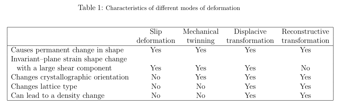
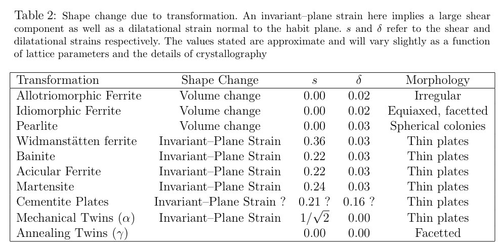
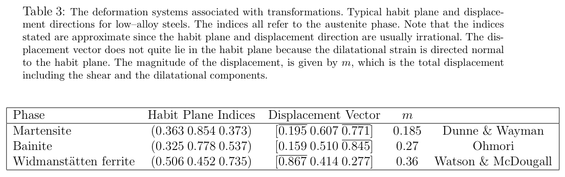
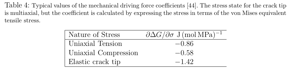
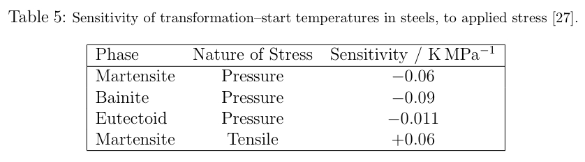
![\includegraphics[width=12cm]{stress.eps}](img52.png)
![\includegraphics[width=12cm]{modified.eps}](img60.png)