Modelling the Evolution of Microstructure in Steel Weld Metals, Mathematical Modelling of Weld Phenomena, pp. 109-182, by H. K. D. H. Bhadeshia and L.-E. Svensson, Eds. H. Cerjak and K. E. Eastering, Institute of Materials, London (1993)

|
|
Modelling the Evolution of Microstructure in Steel Weld Metals, Mathematical Modelling of Weld Phenomena, pp. 109-182, by H. K. D. H. Bhadeshia and L.-E. Svensson, Eds. H. Cerjak and K. E. Eastering, Institute of Materials, London (1993) |
H. K. D. H. Bhadeshia and *L.-E. Svensson
University of Cambridge
Materials Science and Metallurgy
Pembroke Street, Cambridge CB2 3QZ, U. K.
www.phase-trans.msm.cam.ac.uk
.
*ESAB AB, Gothenburg, Sweden
Physical models for the development of microstructure have the potential of revealing new phenomena and properties. They can also help identify the controlling variables. The ability to model weld metal microstructure relies on a deep understanding of the phase transformation theory governing the changes which occur as the weld solidifies and cools to ambient temperature. Considerable progress has been made with the help of thermodynamic and kinetic theory which accounts for the variety of alloying additions, non-equilibrium cooling conditions and other many other variables necessary to fully specify the welded component. These aspects are reviewed with the aim of presenting a reasonably detailed account of the methods involved, and of some important, outstanding difficulties.
It is now well established that extremely small concentrations of certain elements can significantly influence the transformation behaviour of weld metals. Some of these elements are identical to those used in the manufacture of wrought microalloyed steels, whereas others enter the fusion zone as an unavoidable consequence of the welding process. The theory available to cope with such effects is as yet inadequate. Methods for incorporating the influence of trace elements such as oxygen, aluminium, boron, nitrogen, titanium and the rare earth elements into schemes for the prediction of microstructure are discussed. The very high sensitivity of modern microalloyed steels to carbon concentration is also assessed. Some basic ideas on how the approximate relationships between weld microstructure and mechanical properties can be included in computer models are discussed.
Welding procedures have in the past been developed empirically, with some assessment of mechanical properties, and by drawing on accumulated experience. This method has been very successful, as evident in the popularity of the process in virtually all structural engineering applications. It is usually as an afterthought that the macrostructure and microstructure are examined with a view to developing a deeper understanding of the weld, at a more gentle pace when compared against the demands of commercial timetables. This pragmatic approach is hardly surprising in view of the complexity of the microstructural phenomena associated with weld deposits and their heat affected zones. Nevertheless, in an ideal world, the microstructure should take early prominence in the research, especially when there are clear indications that it limits the achievable properties of the weld.
A rational approach towards the design of welding alloys and procedures, can benefit from the development of quantitative and reliable models capable of relating the large number of variables
involved (such as chemical composition, heat input and joint design) to the details of the microstructure (e.g., volume fractions, phase chemistries, particle sizes and distribution). It is
for this reason that the subject of microstructure modelling in steel welds has mushroomed to a point where it is now possible to obtain reasonable estimates of the influence of variables such as
chemical composition on the deposit characteristics ![]() .
.
A number of reviews have recently been compiled on the subject addressed here (Bhadeshia, 1987; 1990). Space limitations have, however, limited these reviews to rather cursory treatments. The opportunity is taken here to present an updated, and more comprehensive assessment of the research on the modelling of weld metal microstructures. Our aim is to make the article useful for learning, especially for those who do not wish to consult and coordinate the information to be found in the large number of research papers on the subject. Although the paper deals specifically with weld metals, most of the phase transformations concepts should also be applicable to wrought alloys.
Pure iron is an exciting element: in its solid state, it has three allotropic forms called austenite (![]() ),
ferrite and
),
ferrite and ![]() -iron. The latter has a hexagonal close-packed crystal structure, is the highest density state of
iron, and is only stable at very large pressures. At ambient pressures, ferrite is stable at temperatures just below the equilibrium melting temperature (in which case it is called
-iron. The latter has a hexagonal close-packed crystal structure, is the highest density state of
iron, and is only stable at very large pressures. At ambient pressures, ferrite is stable at temperatures just below the equilibrium melting temperature (in which case it is called ![]() ) and at relatively low temperatures as the
) and at relatively low temperatures as the ![]() form. Austenite is the stable form in the intervening temperature range between the
form. Austenite is the stable form in the intervening temperature range between the ![]() and
and ![]() . As was recognised a long time ago by Zener and others, this complicated (but useful) behaviour is related to
electronic and magnetic changes as a function of temperature.
. As was recognised a long time ago by Zener and others, this complicated (but useful) behaviour is related to
electronic and magnetic changes as a function of temperature.
The phase behaviour of pure iron does not change radically with the addition of small amounts of solute, i.e., for low-alloy steels. Lightly alloyed steel weld deposits begin
solidification with the epitaxial growth of delta-ferrite (![]() ) from the hot grain structure of the parent plate at
the fusion boundary (Davies & Garland, 1975; Savage et al., 1965; Savage & Aaronson, 1966). The large temperature gradients at the solid/liquid interface ensure that
solidification proceeds with a cellular front (Calvo et al., 1963), so that the final
) from the hot grain structure of the parent plate at
the fusion boundary (Davies & Garland, 1975; Savage et al., 1965; Savage & Aaronson, 1966). The large temperature gradients at the solid/liquid interface ensure that
solidification proceeds with a cellular front (Calvo et al., 1963), so that the final ![]() -grains are
columnar in shape, the major axes of the grains lying roughly along the direction of maximum heat flow (Fig. 1a). On further cooling, austenite allotriomorphs
nucleate at the
-grains are
columnar in shape, the major axes of the grains lying roughly along the direction of maximum heat flow (Fig. 1a). On further cooling, austenite allotriomorphs
nucleate at the ![]() -ferrite grain boundaries, and their higher rate of growth along the
-ferrite grain boundaries, and their higher rate of growth along the ![]() -
-![]() boundaries (and presumably, along temperature
gradients) leads to the formation of columnar austenite grains whose shape resembles that of the original solidification structure. Since welding involves a moving heat source, the orientation of the
temperature isotherms alters with time. Consequently, the major growth direction of the austenite is found to be somewhat different from that of the
boundaries (and presumably, along temperature
gradients) leads to the formation of columnar austenite grains whose shape resembles that of the original solidification structure. Since welding involves a moving heat source, the orientation of the
temperature isotherms alters with time. Consequently, the major growth direction of the austenite is found to be somewhat different from that of the ![]() -grains (Dadian, 1986).
-grains (Dadian, 1986).
If the cooling rate is large enough, then the liquid can be induced to solidify as metastable austenite instead, Fig. 1b. This could happen even when ![]() -ferrite is the thermodynamically favoured phase in low-alloy steels (Fredriksson, 1976; 1983). It has been suggested
that this is especially likely when the partition coefficient
-ferrite is the thermodynamically favoured phase in low-alloy steels (Fredriksson, 1976; 1983). It has been suggested
that this is especially likely when the partition coefficient ![]() is closer to unity for austenite than for
ferrite.
is closer to unity for austenite than for
ferrite. ![]() and
and ![]() are the solute
solubilities in the solid and liquid phases respectively (Fredriksson, 1976). The austenite growth rate can in those circumstances exceed that of
are the solute
solubilities in the solid and liquid phases respectively (Fredriksson, 1976). The austenite growth rate can in those circumstances exceed that of ![]() -ferrite when the liquid is sufficiently undercooled. Solidification with austenite as the primary phase becomes more feasible as the steel is alloyed with austenite
stabilising elements, until the
-ferrite when the liquid is sufficiently undercooled. Solidification with austenite as the primary phase becomes more feasible as the steel is alloyed with austenite
stabilising elements, until the ![]() eventually becomes the thermodynamically stable phase.
eventually becomes the thermodynamically stable phase.
![\includegraphics[width=15cm]{Fig1.eps}](img10.png) |
Solidification to austenite can be undesirable for two reasons; large inclusions tend to become trapped preferentially at the cusps in the advancing solid/liquid interface and end up at the
columnar grain boundaries (Sugden & Bhadeshia, 1988a). When austenite forms directly from the liquid, the inclusions are located in the part of the weld which in the final microstructure
corresponds to relatively brittle allotriomorphic ferrite (Fig. 2). This is not the case with ![]() solidification since during subsequent transformation, the daughter austenite grains cut across the
solidification since during subsequent transformation, the daughter austenite grains cut across the ![]() grain boundaries, leaving the large inclusions inside the grains where they can do less harm, and perhaps also be of use in stimulating the nucleation of acicular ferrite.
The second reason to avoid
grain boundaries, leaving the large inclusions inside the grains where they can do less harm, and perhaps also be of use in stimulating the nucleation of acicular ferrite.
The second reason to avoid ![]() solidification diffusion rate of substitutional elements is orders of magnitude
larger in ferrite than in austenite, so that any segregation is less likely to persist when the liquid transforms to ferrite (Fredriksson, 1976, 1983).
solidification diffusion rate of substitutional elements is orders of magnitude
larger in ferrite than in austenite, so that any segregation is less likely to persist when the liquid transforms to ferrite (Fredriksson, 1976, 1983).
![\includegraphics[width=15cm]{Fig2.eps}](img12.png) |
Both the shape and size of the austenite grains is of importance in the evolution of the final microstructure. The effect of the austenite grain size is two fold: there is firstly the usual phenomenon in which the number density of austenite grain boundary heterogeneous nucleation sites increases with the total grain boundary area per unit volume of sample. This amounts to the classical and well established hardenability variation with austenite grain size. The second, and more subtle effect, arises from the grain-shape anisotropy. Although the columnar grains of austenite are very long, the evolution of many aspects of the microstructure within an individual austenite grain is dependent on the mean lineal intercept within that grain. Since the chances of test lines lying parallel to the longest dimension of the columnar grain are small, the mean lineal intercept depends mainly on the width of the grain. As will be seen later, this means that the grain length can often be excluded as a factor in the calculation of microstructure.
The anisotropy of grain structure causes certain complications in representing the grain parameters in any microstructure model. The morphology can be described approximately by a uniform,
space-filling array of hexagonal prisms,Fig. 2b (Bhadeshia et al., 1986a). An approximation is that the elongated austenite grains curve as they grow
into the weld pool, in response to the changing orientation of the isotherms. The actual grains are also not of uniform size. Each hexagonal prism can be represented by its length ![]() and cross-sectional side length
and cross-sectional side length ![]() . With these
approximations, the mean lineal intercept
. With these
approximations, the mean lineal intercept ![]() and mean areal intercept
and mean areal intercept ![]() , as measured from several differently oriented sections are given by (Underwood, 1970):
, as measured from several differently oriented sections are given by (Underwood, 1970):
 |
(1) |
 |
(2) |
 |
(3) |
The approximations involved in the determination of ![]() from
from ![]() are valid when the weld is deposited in the flat position. For vertical-up welds, the
austenite grains adopt an orientation in which they do not present very anisotropic shapes in the transverse section, often tending instead to acquire an equiaxed shape (Evans, 1981; Svensson, 1986).
The
are valid when the weld is deposited in the flat position. For vertical-up welds, the
austenite grains adopt an orientation in which they do not present very anisotropic shapes in the transverse section, often tending instead to acquire an equiaxed shape (Evans, 1981; Svensson, 1986).
The ![]() -axes of the hexagonal prisms are then inclined at a relatively shallow angle
-axes of the hexagonal prisms are then inclined at a relatively shallow angle ![]() , estimated to be
, estimated to be ![]() for manual metal arc welds by Evans (1981), to the welding direction and hence to the plate
surface. Consequently, for vertical-up welds, it can be demonstrated that the mean lineal intercept measured on the transverse section (with the test lines oriented at random with respect to the
grain structure) is given by
for manual metal arc welds by Evans (1981), to the welding direction and hence to the plate
surface. Consequently, for vertical-up welds, it can be demonstrated that the mean lineal intercept measured on the transverse section (with the test lines oriented at random with respect to the
grain structure) is given by
|
(4) |
From the above discussion, it appears that the current methods of measuring the columnar austenite grain structure via ![]() provide adequate information for microstructure modelling. It is however anticipated, that as
the phase transformation models increase in sophistication, it will be necessary to think more in terms of the total austenite grain surface per unit volume of sample (
provide adequate information for microstructure modelling. It is however anticipated, that as
the phase transformation models increase in sophistication, it will be necessary to think more in terms of the total austenite grain surface per unit volume of sample (![]() ). This parameter will in general require measurements to be made on several differently orientated planes of section relative to the columnar
grains. For a typical weld microstructure, an approximation of
). This parameter will in general require measurements to be made on several differently orientated planes of section relative to the columnar
grains. For a typical weld microstructure, an approximation of ![]() based on just
based on just ![]() is likely to lead to an error of about 30% (see for example, Bhadeshia et al.,
1986a).
is likely to lead to an error of about 30% (see for example, Bhadeshia et al.,
1986a).
Another assumption usually made in specifying the austenite grain structure of welds is that it is uniform. In fact, because growth begins epitaxially from the fusion surface, the grain structure changes with distance. Those grains whose fast-growth directions are favourably orientated with respect to the heat-flow tend to stifle the others as directional solidification proceeds.
It is not possible as yet to predict the austenite grain size (e.g., ![]() ) of steel welds; even the factors controlling this grain size are far from clear. It has
naturally been assumed, by extrapolation from grain growth theory, that the nonmetallic inclusions which are common in steel welds control the grain size by Zener pinning the boundaries. This analogy
is however, not justified since the austenite grains form by the transformation of
) of steel welds; even the factors controlling this grain size are far from clear. It has
naturally been assumed, by extrapolation from grain growth theory, that the nonmetallic inclusions which are common in steel welds control the grain size by Zener pinning the boundaries. This analogy
is however, not justified since the austenite grains form by the transformation of ![]() -ferrite, whereas
Zener pinning deals with the hindrance of grain boundaries during grain growth. The driving force for grain growth typically amounts to just a few Joules per mole, whereas that for transformation
from
-ferrite, whereas
Zener pinning deals with the hindrance of grain boundaries during grain growth. The driving force for grain growth typically amounts to just a few Joules per mole, whereas that for transformation
from ![]() -ferrite to austenite increases indefinitely with undercooling below the equilibrium transformation
temperature. Pinning of
-ferrite to austenite increases indefinitely with undercooling below the equilibrium transformation
temperature. Pinning of ![]() interfaces cannot then be effective. A mechanism in which inclusions pin the columnar austenite
grain boundaries is also inconsistent with the shape of these grains, since the motion of the
interfaces cannot then be effective. A mechanism in which inclusions pin the columnar austenite
grain boundaries is also inconsistent with the shape of these grains, since the motion of the ![]() interfaces along the steepest temperature gradients is clearly not restricted; if pinning were effective, the austenite grains that evolve should be isotropic.
interfaces along the steepest temperature gradients is clearly not restricted; if pinning were effective, the austenite grains that evolve should be isotropic.
There is some evidence to support the conclusion that the columnar austenite grain size is not influenced by for example, the oxygen content of the weld (Bhadeshia et al., 1985a, 1986a).
Experiments to the contrary (Harrison & Farrar, 1981) really refer to the reheated weld metal, where the grain size is related to a coarsening reaction driven by ![]() surface energy. On the other hand, there are data which indicate that low weld oxygen
concentrations correlate with large columnar austenite grain sizes (Fleck et al., 1986). There is a possible explanation for these contradictory results. If it is assumed that in some cases,
e.g., when the initial austenite grain size is extremely fine, the columnar austenite grain structure coarsens during cooling after solidification. North et al. (1990) have
presented evidence to reveal such coarsening. Further work is needed urgently to clarify these issues.
surface energy. On the other hand, there are data which indicate that low weld oxygen
concentrations correlate with large columnar austenite grain sizes (Fleck et al., 1986). There is a possible explanation for these contradictory results. If it is assumed that in some cases,
e.g., when the initial austenite grain size is extremely fine, the columnar austenite grain structure coarsens during cooling after solidification. North et al. (1990) have
presented evidence to reveal such coarsening. Further work is needed urgently to clarify these issues.
The columnar austenite grain size must to some extent correlate with the grain size in the parent plate at the fusion boundary, since solidification occurs by the epitaxial growth of those grains
(Davies & Garland, 1975). However, the relationship cannot be simple, since during solidification, those grains with their ![]() directions most parallel to the direction of steepest temperature gradient grow rapidly, stifling the grains which are not suitably oriented. Consequently, the
crystallographic texture of the parent plate, and the plane of that plate on which the weld is deposited, must influence the final austenite grain structure. Clear differences in the austenite grain
structure were found between three welds deposited on mutually perpendicular faces of the same sample, in a recent experiment designed to illustrate the influence of crystallographic texture on the
grain size (Babu et al., 1991). More systematic work is now called for. A corollary is that particles in the parent plate (e.g., carbo-nitrides) may limit the coarsening of the
plate grains at the fusion boundary, and therefore lead ultimately to a smaller grain size in the fusion zone.
directions most parallel to the direction of steepest temperature gradient grow rapidly, stifling the grains which are not suitably oriented. Consequently, the
crystallographic texture of the parent plate, and the plane of that plate on which the weld is deposited, must influence the final austenite grain structure. Clear differences in the austenite grain
structure were found between three welds deposited on mutually perpendicular faces of the same sample, in a recent experiment designed to illustrate the influence of crystallographic texture on the
grain size (Babu et al., 1991). More systematic work is now called for. A corollary is that particles in the parent plate (e.g., carbo-nitrides) may limit the coarsening of the
plate grains at the fusion boundary, and therefore lead ultimately to a smaller grain size in the fusion zone.
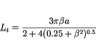
Regression equations are currently used in making crude estimates of the columnar austenite grain size:
| (5) |
A calculation of microstructure requires a detailed description of each phase. For example, the growth rate of a particle cannot be estimated without a knowledge of the compositions of the parent and product phases at the interface. The simplest assumption would be to assume diffusion-controlled growth, in which case, the compositions are, for a binary alloy at least, given by a tie-line of the equilibrium phase diagram. The formation of the particle may be associated with the development of elastic strains, especially if the mechanism of transformation is displacive. These strains lead to a modification of the phase diagram, and might alter the particle-shape in an effort to minimise the strain energy.
Work on weld metal microstructures has evolved along different lines when compared against the mainstream of steel research. In an effort to develop microstructure-property relationships, there has been an exaggerated emphasis on purely microstructural observations. There are some difficulties with the notation, which is derived largely from morphological observations rather than from the details of the mechanism of transformation, which are also essential for quantitative work.
The microstructure obtained as the weld cools from the liquid phase to ambient temperature is called the as-deposited or primary microstructure. It consists of allotriomorphic
ferrite ![]() , Widmanstätten ferrite
, Widmanstätten ferrite ![]() , acicular ferrite
, acicular ferrite ![]() , and the so-called microphases, which might include small amounts of
martensite, retained austenite or degenerate pearlite (Fig. 3). Bainite is also found in some weld deposits, particularly of the type used in the power
generation industry (Lundin et al., 1986). Allotriomorphic ferrite is sometimes called ``polygonal" ferrite or ``proeutectoid" ferrite, but polygonal simply means many sided (like all
ferrite morphologies) and Widmanstätten ferrite can also be proeutectoid. Widmanstätten ferrite is sometimes included under the general description ``ferrite with aligned MAC", the
abbreviation referring to martensite, austenite and carbide. However, bainite plates can also form in a similar shape, although their thermodynamic and kinetic characteristics are quite different.
From a phase transformations point of view, the Dubé classification of ferrite grains remains the most useful to this day (Dubé et al., 1958; Heckel & Paxton, 1961).
, and the so-called microphases, which might include small amounts of
martensite, retained austenite or degenerate pearlite (Fig. 3). Bainite is also found in some weld deposits, particularly of the type used in the power
generation industry (Lundin et al., 1986). Allotriomorphic ferrite is sometimes called ``polygonal" ferrite or ``proeutectoid" ferrite, but polygonal simply means many sided (like all
ferrite morphologies) and Widmanstätten ferrite can also be proeutectoid. Widmanstätten ferrite is sometimes included under the general description ``ferrite with aligned MAC", the
abbreviation referring to martensite, austenite and carbide. However, bainite plates can also form in a similar shape, although their thermodynamic and kinetic characteristics are quite different.
From a phase transformations point of view, the Dubé classification of ferrite grains remains the most useful to this day (Dubé et al., 1958; Heckel & Paxton, 1961).
The above description is incomplete for multirun welds, in which some of the regions of original primary microstructure are reheated to temperatures high enough to cause reverse transformation into austenite, which during the cooling part of the thermal cycle retransforms into a variety of somewhat different products. Other regions may simply be tempered by the deposition of subsequent runs. The microstructure of the reheated regions is called the reheated or secondary microstructure.
A detailed classification of microstructure, based on the kind of knowledge needed in its calculation, is presented in Appendix 1.
![\includegraphics[width=12cm]{Fig3.eps}](img37.png) |
Allotriomorphic ferrite (![]() ) is the first phase to form on cooling below the
) is the first phase to form on cooling below the ![]() temperature and nucleates heterogeneously at the boundaries of the columnar austenite grains. The fundamental aspects of allotriomorphic ferrite
have been reviewed in detail (Bhadeshia, 1985a), where many of the original references can also be found. In low alloy steel welds, the boundaries rapidly become decorated with virtually continuous
layers of ferrite, so that subsequent transformation simply involves the reconstructive thickening of these layers, a process which can be modelled in terms of the normal migration of planar
temperature and nucleates heterogeneously at the boundaries of the columnar austenite grains. The fundamental aspects of allotriomorphic ferrite
have been reviewed in detail (Bhadeshia, 1985a), where many of the original references can also be found. In low alloy steel welds, the boundaries rapidly become decorated with virtually continuous
layers of ferrite, so that subsequent transformation simply involves the reconstructive thickening of these layers, a process which can be modelled in terms of the normal migration of planar ![]() /
/![]() interfaces. The assumption
involved implies that the initial formation of a thin, continuous layer of allotriomorphic ferrite takes a much smaller time when compared with its subsequent thickening to the final size. The
assumption is supported, at least for low-alloy steel welds, by the fact that the volume fraction of allotriomorphic ferrite correlates strongly with its growth kinetics Fig. 4. Dallum and Olson (1989) have demonstrated that the thickness of the allotriomorphic ferrite layer is insensitive to the initial austenite grain size, at least for
the low-alloy steel and heat-treatment conditions they utilised. A result like this can only be justified if it is assumed that nucleation does not have a great influence on the overall
transformation kinetics.
interfaces. The assumption
involved implies that the initial formation of a thin, continuous layer of allotriomorphic ferrite takes a much smaller time when compared with its subsequent thickening to the final size. The
assumption is supported, at least for low-alloy steel welds, by the fact that the volume fraction of allotriomorphic ferrite correlates strongly with its growth kinetics Fig. 4. Dallum and Olson (1989) have demonstrated that the thickness of the allotriomorphic ferrite layer is insensitive to the initial austenite grain size, at least for
the low-alloy steel and heat-treatment conditions they utilised. A result like this can only be justified if it is assumed that nucleation does not have a great influence on the overall
transformation kinetics.
![\includegraphics[width=12cm]{Fig4.eps}](img39.png) |
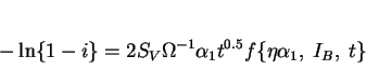
Given these facts, and assuming that the growth of allotriomorphic ferrite occurs under paraequilibrium conditions, then the half-thickness ![]() of the layer during isothermal growth is given by:
of the layer during isothermal growth is given by:
 |
(6) |
Paraequilibrium is a constrained equilibrium in which the ratio of iron to substitutional solute concentration remains constant everywhere, but subject to that constraint, the carbon achieves
equality of chemical potential (Hultgren, 1951; Hillert, 1952; Rudberg, 1952). It seems a reasonable assumption given that welds generally cool at a rapid rate. The parabolic rate constant is
obtained by solving the equation:
 |
 |
![\includegraphics[width=12cm]{Fig5.eps}](img51.png) |
The calculation of the parabolic rate constants also requires a knowledge of the chemical compositions of the phases at the transformation interfaces, and for diffusion-controlled growth, these compositions can be deduced approximately using the phase diagram which can nowadays easily be computed, even for multicomponent steels (e.g., Bhadeshia & Edmonds, 1980). Some typical kinetic data for allotriomorphic ferrite are presented in Fig. 6. Note that none of these calculations take account of soft-impingement effects, i.e., the retardation in growth kinetics due to the overlap of concentration fields of particles growing from different positions, or because the concentration in the austenite at its furthest point from the ferrite becomes enriched. It is known (Vandermeer et al., 1989) that soft-impingement has a large influence on the growth kinetics, and further work is needed to incorporate it into the current weld microstructure models. The effects should become more prominent as the volume fraction of ferrite increases, or as the austenite grain size decreases.
![\includegraphics[width=12cm]{Fig6.eps}](img52.png) |
That the formation of allotriomorphic ferrite in most welds is dependent largely on the rate of growth is apparent from the good correlation between ![]() and the volume fraction of
and the volume fraction of ![]() obtained (Bhadeshia et al.,
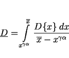
1985b). A better understanding of the role of alloy elements requires a method for estimating the volume fraction of allotriomorphic ferrite. This can be done by integrating the thickening of the
layers over a temperature range
obtained (Bhadeshia et al.,
1985b). A better understanding of the role of alloy elements requires a method for estimating the volume fraction of allotriomorphic ferrite. This can be done by integrating the thickening of the
layers over a temperature range ![]() to
to ![]() . Allotriomorphic ferrite growth begins at
. Allotriomorphic ferrite growth begins at ![]() , a temperature which can be estimated using a calculated
, a temperature which can be estimated using a calculated ![]() curve (Bhadeshia, 1982; 1988a), and Scheil's rule (Christian, 1975) to allow for the fact that the process involves
continuous cooling transformation. It ``finishes" at
curve (Bhadeshia, 1982; 1988a), and Scheil's rule (Christian, 1975) to allow for the fact that the process involves
continuous cooling transformation. It ``finishes" at ![]() , the temperature where the reconstructive and displacive
, the temperature where the reconstructive and displacive ![]() -curves of the
-curves of the ![]() diagram intersect
(i.e., where displacive transformations have a kinetic advantage). Thus
diagram intersect
(i.e., where displacive transformations have a kinetic advantage). Thus
 |
(7) |
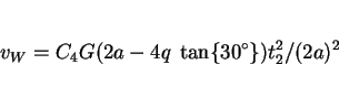
Notice that the expression also relies on the unverified assumption that the compositions of the phases at the interface instantaneously adjust themselves to the phase diagram as the temperature
is lowered. The volume fraction of ferrite is then given by
![\begin{displaymath}v_\alpha = {{2q~\tan\{30^\circ\}[2a - 2q~\tan\{30^\circ\}]}\over{a^2}} \end{displaymath}](img60.png)
|
(8) |
 |
(9) |
Fleck et al. (1986) have adopted a different approach based on an Avrami type equation:
 |
(10) |
 |
(11) |
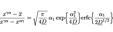
There are two major causes of chemical segregation in welds, the relatively large cooling rates involved and variations in process parameters during welding. The latter cannot in general be
accurately predicted, but the extent of segregation due to nonequilibrium solidification can be estimated from the partition coefficient ![]() which is the ratio of the concentration of element
which is the ratio of the concentration of element ![]() in the
in the ![]() -ferrite to that in the liquid phase. The coefficient can be calculated for the liquidus temperature, and the minimum concentration to be
found in a heterogeneous solid weld is then taken to be
-ferrite to that in the liquid phase. The coefficient can be calculated for the liquidus temperature, and the minimum concentration to be
found in a heterogeneous solid weld is then taken to be ![]() . This is the composition of the solute-depleted region of the weld, since it is assumed that
diffusion during cooling to ambient temperatures does not lead to significant homogenisation (Gretoft et al., 1986). Carbon, which diffuses much more rapidly than substitutional solutes, is
assumed to be homogeneously distributed in the austenite prior to transformation.
. This is the composition of the solute-depleted region of the weld, since it is assumed that
diffusion during cooling to ambient temperatures does not lead to significant homogenisation (Gretoft et al., 1986). Carbon, which diffuses much more rapidly than substitutional solutes, is
assumed to be homogeneously distributed in the austenite prior to transformation.
The method for incorporating the effect of substitutional solute segregation into weld microstructure calculations, is via the influence on the temperature at which the allotriomorphic ferrite
begins to grow (![]() ). In general, it is the solute depleted regions which should transform first to ferrite. Thus, the
TTT diagram used for estimating
). In general, it is the solute depleted regions which should transform first to ferrite. Thus, the
TTT diagram used for estimating ![]() should be calculated not from the average composition of the steel, but using the
composition of the solute depleted regions.
should be calculated not from the average composition of the steel, but using the
composition of the solute depleted regions.
This procedure seems to work well, presumably because the major effect of substitutional solute segregation during the welding of low-alloy steels is on enhancing the nucleation of allotriomorphic
ferrite, and hence on the temperature range ![]() (Gretoft et al., 1986; Strangwood & Bhadeshia, 1987b). The effect of chemical
segregation becomes more pronounced as the level of alloying additions rises.
(Gretoft et al., 1986; Strangwood & Bhadeshia, 1987b). The effect of chemical
segregation becomes more pronounced as the level of alloying additions rises.
It has in the past been accepted that allotriomorphic ferrite is bad for weld metal toughness because it offers little resistance to cleavage crack propagation. However, it is a reconstructive
transformation involving the diffusion of all atoms, so that grains of ![]() can grow freely across
can grow freely across ![]() grain boundaries, into all of the adjacent grains. Displacive transformations (Widmanstätten ferrite, bainite, acicular
ferrite, martensite) involve the coordinated movement of atoms, and such movements cannot be sustained across grain boundaries. Hence, a vestige of the
grain boundaries, into all of the adjacent grains. Displacive transformations (Widmanstätten ferrite, bainite, acicular
ferrite, martensite) involve the coordinated movement of atoms, and such movements cannot be sustained across grain boundaries. Hence, a vestige of the ![]() grain boundary remains when the transformation products are all displacive, and in the presence of impurities, can lead to intergranular failure with
respect to the prior austenite grain boundaries. With allotriomorphic ferrite, the original
grain boundary remains when the transformation products are all displacive, and in the presence of impurities, can lead to intergranular failure with
respect to the prior austenite grain boundaries. With allotriomorphic ferrite, the original ![]() boundaries are
entirely disrupted, removing the site for the segregation of impurities. This conclusion is supported by observations reported in the literature. Abson (1988) examined a large set of weld deposits.
Of these, a particular weld which had no allotriomorphic ferrite content and a particularly high concentration of phosphorus exhibited brittle failure at the prior columnar austenite grain boundaries
in the manner illustrated in Fig. 7.
boundaries are
entirely disrupted, removing the site for the segregation of impurities. This conclusion is supported by observations reported in the literature. Abson (1988) examined a large set of weld deposits.
Of these, a particular weld which had no allotriomorphic ferrite content and a particularly high concentration of phosphorus exhibited brittle failure at the prior columnar austenite grain boundaries
in the manner illustrated in Fig. 7.
It is well known that the post-weld heat treatment (600 ![]() C) of titanium and boron containing welds leads to
embrittlement with failure at the columnar austenite grain boundaries (Still and Rogerson, 1978, 1980; Kluken and Grong, 1992). Phosphorus has been shown to segregate to these prior austenite
boundaries and cause a deterioration in the toughness. The titanium and boron make the welds sensitive to post-weld heat treatment because they prevent allotriomorphic ferrite, and hence expose the
remains of the austenite grain boundaries to impurity segregation.
C) of titanium and boron containing welds leads to
embrittlement with failure at the columnar austenite grain boundaries (Still and Rogerson, 1978, 1980; Kluken and Grong, 1992). Phosphorus has been shown to segregate to these prior austenite
boundaries and cause a deterioration in the toughness. The titanium and boron make the welds sensitive to post-weld heat treatment because they prevent allotriomorphic ferrite, and hence expose the
remains of the austenite grain boundaries to impurity segregation.
Kayali et al. (1984) and Lazor and Kerr (1980) have reported such failure, again in welds containing a microstructure which consisted only of acicular ferrite. Sneider and Kerr (1984) have noted that such fracture appears to be encouraged by excessive alloying. Boron is important in this respect because it can lead to an elimination of austenite grain boundary nucleated phases; recent observations on intergranular fracture at the prior austenite boundaries (Kluken et al., 1994) can be interpreted in this way. This is consistent with our hypothesis, since large austenite-stabilising solute concentrations tend to reduce the allotriomorphic ferrite content.
It must be emphasised that it is not the reduction in allotriomorphic ferrite content per se which worsens the properties; the important factor is the degree of coverage (and hence
disruption) of the prior austenite grain surfaces. In addition, the impurity content has to be high enough relative to the amount of prior austenite grain surface, to cause embrittlement. Classical
temper embrittlement theory suggests that additions of elements like molybdenum should mitigate the effects of impurity controlled embrittlement, although such ideas need to be tested for the
as-deposited microstructure of steel welds. To summarise, it is likely that ![]() should not entirely be designed out
of weld microstructures, especially if the weld metal is likely to contain a significant impurity concentration.
should not entirely be designed out
of weld microstructures, especially if the weld metal is likely to contain a significant impurity concentration.
![\includegraphics[width=12cm]{Fig7.eps}](img77.png) |
Recent work reinforces the conclusion that some allotriomorphic ferrite should be retained in the weld microstructure in order to improve its high temperature mechanical properties. Ichikawa et al. (1994b) examined the mechanical properties of large heat input submerged arc welds designed for fire-resistant steels. They demonstrated that the high temperature ductility and the creep rupture life of the welds deteriorated sharply in the absence of allotriomorphic ferrite (Fig. 8). The associated intergranular fracture, with respect to the prior austenite grain boundaries, became intragranular when some allotriomorphic ferrite was introduced into the microstructure.
![\includegraphics[width=12cm]{Fig8.eps}](img78.png) |
Steel can be infiltrated at the prior austenite grain boundaries by liquid zinc. In a study of the heat-affected zone of steel welds, Iezawa et al. (1993) demonstrated that their susceptibility to liquid zinc embrittlement depended on the allotriomorphic ferrite content, which in turn varied with the boron concentration (Fig. 8). The absence of allotriomorphs at the prior austenite grain boundaries clearly made them more sensitive to zinc infiltration, proving again that these boundaries have a high-energy structure which is susceptible to wetting and impurity segregation.
The rutile based electrode systems currently under development generally lead to phosphorus concentrations of about 0.010-0.015 wt.%, and the popular use of titanium and boron gives a weld deposit without allotriomorphic ferrite. The welds have therefore been found to be extremely susceptible to stress relief embrittlement with fracture along the prior austenite grain boundaries. Possible solutions include:
It was argued above that with displacive transformations (which cannot cross austenite grain boundaries), a ``vestige" of the austenite grain boundary structure is left in the microstructure. The following evidence suggests that these prior austenite grain boundaries are high-energy boundaries:
Why then is the misfit present at austenite grain boundaries inherited in fully transformed specimens when the mechanism of transformation is displacive? The answer to this lies in the fact that
the displacive transformation of austenite involves a minimal movement of atoms. The Bain Strain, which is the pure component of the deformation which converts the austenite lattice into that of
ferrite, does not rotate any plane or direction by more than about ![]() . Furthermore, the change in volume
during transformation is a few percent. The excellent registry between the parent and product lattices is illustrated by the electron diffraction pattern of Fig.
9.
. Furthermore, the change in volume
during transformation is a few percent. The excellent registry between the parent and product lattices is illustrated by the electron diffraction pattern of Fig.
9.
Consequently, the detailed arrangement of atoms at an austenite grain boundary is unlikely to be influenced greatly by displacive phase transformation.
![\includegraphics[width=12cm]{Fig10.eps}](img81.png) |
The paraequilibrium formation of ![]() can occur at relatively small driving forces (Bhadeshia, 1981a, 1985b,
1988b), and the strain energy due to its displacive transformation mechanism is mitigated by the cooperative, back-to-back growth of self-accommodating crystallographic variants (leading to a small
strain energy term of
can occur at relatively small driving forces (Bhadeshia, 1981a, 1985b,
1988b), and the strain energy due to its displacive transformation mechanism is mitigated by the cooperative, back-to-back growth of self-accommodating crystallographic variants (leading to a small
strain energy term of ![]() ). The
). The ![]() seen using a light microscope can be visualised as consisting of two mutually accommodating plates with slightly different habit plane indices, giving the characteristic thin
wedge morphology of
seen using a light microscope can be visualised as consisting of two mutually accommodating plates with slightly different habit plane indices, giving the characteristic thin
wedge morphology of ![]() . The shape of the plate can be approximated by a thin wedge of length
. The shape of the plate can be approximated by a thin wedge of length ![]() in the major growth direction, growth in the other two dimensions soon becoming stifled by impingement with the diffusion fields of
nearby plates in a packet. The details of this model, particularly the fact that it predicts that the volume fraction of Widmanstätten ferrite should be proportional to the plate length, need to
be verified further. At first sight, such a dependence could only arise if the Widmanstätten ferrite developed into a lath rather than a plate shape.
in the major growth direction, growth in the other two dimensions soon becoming stifled by impingement with the diffusion fields of
nearby plates in a packet. The details of this model, particularly the fact that it predicts that the volume fraction of Widmanstätten ferrite should be proportional to the plate length, need to
be verified further. At first sight, such a dependence could only arise if the Widmanstätten ferrite developed into a lath rather than a plate shape.
The lengthening rate ![]() of Widmanstätten ferrite can be estimated using the Trivedi (1970) theory for the
diffusion-controlled growth of parabolic cylinders (Bhadeshia, 1985b). Because of its shape, and unlike allotriomorphic ferrite, Widmanstätten ferrite grows at a constant rate as long as
soft-impingement (overlap of diffusion fields) does not occur. The calculated growth rates are found to be so large for typical weld deposits, that the formation of Widmanstätten ferrite is
usually complete within a fraction of a second. Hence, for all practical purposes, the transformation can be treated as being isothermal (Fig. 10a).
of Widmanstätten ferrite can be estimated using the Trivedi (1970) theory for the
diffusion-controlled growth of parabolic cylinders (Bhadeshia, 1985b). Because of its shape, and unlike allotriomorphic ferrite, Widmanstätten ferrite grows at a constant rate as long as
soft-impingement (overlap of diffusion fields) does not occur. The calculated growth rates are found to be so large for typical weld deposits, that the formation of Widmanstätten ferrite is
usually complete within a fraction of a second. Hence, for all practical purposes, the transformation can be treated as being isothermal (Fig. 10a).
![\includegraphics[width=12cm]{Fig11.eps}](img84.png) |
Transformation to Widmanstätten ferrite is taken to begin when that of allotriomorphic ferrite ceases at ![]() ;
the volume fraction is given by
;
the volume fraction is given by
 |
(12) |
![\includegraphics[width=12cm]{Fig12.eps}](img93.png) |
``Acicular ferrite" ![]() is a phase most commonly observed as austenite transforms during the cooling of
low-alloy steel weld deposits (see for example, the reviews by Grong and Matlock, 1986; Abson and Pargeter, 1986; and Bhadeshia, 1988b). It is of considerable commercial importance because it
provides a relatively tough and strong microstructure. It forms in a temperature range where reconstructive transformations become relatively sluggish and give way to displacive reactions such as
Widmanstätten ferrite, bainite and martensite.
is a phase most commonly observed as austenite transforms during the cooling of
low-alloy steel weld deposits (see for example, the reviews by Grong and Matlock, 1986; Abson and Pargeter, 1986; and Bhadeshia, 1988b). It is of considerable commercial importance because it
provides a relatively tough and strong microstructure. It forms in a temperature range where reconstructive transformations become relatively sluggish and give way to displacive reactions such as
Widmanstätten ferrite, bainite and martensite.
The transformation has not been studied from a fundamental point of view in any great depth, and so there are as yet no models which allow the volume fraction ![]() of acicular ferrite to be calculated from first principles. For this reason, the mechanism of transformation is reviewed below in some detail. Note
that in spite of the dirth of basic work in this area, for many welds it is nevertheless possible to estimate
of acicular ferrite to be calculated from first principles. For this reason, the mechanism of transformation is reviewed below in some detail. Note
that in spite of the dirth of basic work in this area, for many welds it is nevertheless possible to estimate ![]() via
the equation
via
the equation
 |
(13) |
The term acicular means shaped and pointed like a needle, but it is generally recognised that acicular ferrite has in three-dimensions the morphology of thin, lenticular plates
(Fig. 12). The shape of acicular ferrite is sometimes stated to be rod-like, but there is no evidence to support this. In two-dimensional sections, the acicular
ferrite always appears like a section of a plate rather than of a rod. The true aspect ratio of such plates has never been measured but in random planar sections, the plates are typically about
10![]() long and
long and ![]() wide, so that the true aspect ratio is likely to be much smaller than 0.1.
wide, so that the true aspect ratio is likely to be much smaller than 0.1.
![\includegraphics[width=12cm]{Fig13.eps}](img99.png) |
As the liquid weld pool cools, its solubility of dissolved gasses decreases. Reactions between these gases and other elements causes the formation of solid particles such as oxides. Those
particles formed in the very hot and turbulent region immediately beneath the arc are mostly swept out of the pool (Kluken and Grong, 1989). It is the precipitates that form in the lower, relatively
cold region of the pool that become trapped into the solid weld. An arc-weld deposit typically contains some ![]() inclusions of a size greater than 0.05
inclusions of a size greater than 0.05![]() , distributed throughout the microstructure, although there is a tendency for some of the larger particles to be pushed towards, and consequently trapped
along the solidification-cell boundaries during the advance of the solid-liquid interface (Sugden and Bhadeshia, 1988a). The mean particle size of the inclusions important in influencing the
microstructure is of the order of 0.4
, distributed throughout the microstructure, although there is a tendency for some of the larger particles to be pushed towards, and consequently trapped
along the solidification-cell boundaries during the advance of the solid-liquid interface (Sugden and Bhadeshia, 1988a). The mean particle size of the inclusions important in influencing the
microstructure is of the order of 0.4![]() . It is the interaction of the liquid weld metal with any
surrounding gases, together with the use of strong deoxidising elements such as silicon, aluminium and titanium, and protective slag-forming compounds which causes the entrapment of complex
multiphase nonmetallic inclusions in the solid at the advancing
. It is the interaction of the liquid weld metal with any
surrounding gases, together with the use of strong deoxidising elements such as silicon, aluminium and titanium, and protective slag-forming compounds which causes the entrapment of complex
multiphase nonmetallic inclusions in the solid at the advancing ![]() -ferrite/liquid interface. The inclusions have
two major effects on the steel: they serve the desirable role of promoting the intragranular nucleation of acicular ferrite plates, leading to an improvement in toughness without a loss of strength.
But they also are responsible for the nucleation of voids during ductile fracture, or the nucleation of cleavage cracks during brittle fracture. Achieving a proper balance between these conflicting
factors is very difficult without a basic understanding of the mechanisms controlling these interactions.
-ferrite/liquid interface. The inclusions have
two major effects on the steel: they serve the desirable role of promoting the intragranular nucleation of acicular ferrite plates, leading to an improvement in toughness without a loss of strength.
But they also are responsible for the nucleation of voids during ductile fracture, or the nucleation of cleavage cracks during brittle fracture. Achieving a proper balance between these conflicting
factors is very difficult without a basic understanding of the mechanisms controlling these interactions.
There are now many results which prove that the inclusions responsible for the heterogeneous nucleation of acicular ferrite are themselves inhomogeneous, as illustrated in Fig. 13 (Ito and Nakanishi, 1976; Mori et al., 1981; Kayali et al., 1983; Dowling et al., 1986; Mills et al., 1987; Thewlis, 1989a,b) The microstructure of the inclusions is particularly important from the point of view of developing a clear understanding of their role in stimulating the nucleation of ferrite. As an example, it has been reported that the nonmetallic particles found in some submerged arc weld deposits consist of titanium nitride cores, surrounded by a glassy phase containing manganese, silicon and aluminium oxides, with a thin layer of manganese sulphide (and possibly, titanium oxide) partly covering the surface of the inclusions (Barbaro et al., 1988). This detailed sequence of inclusion formation is not understood and seems to contradict (admittedly simplistic) thermodynamic arguments. For example, titanium oxide is supposed to be thermodynamically more stable than titanium nitride, and yet the latter is the first to form from the liquid phase.
![\includegraphics[width=12cm]{Fig14.eps}](img102.png) |
The inclusions may therefore be oxides or other compounds but they can under some circumstances influence the subsequent development of microstructure during cooling of the weld deposit. Acicular
ferrite plates, during the early stages of transformation nucleate on inclusions present in the large columnar austenite grains which are typical of weld deposits (Ito and Nakanishi, 1976).
Subsequent plates may nucleate autocatalytically, so that a one-to-one correspondence between the number of active inclusions and the number of ![]() plates is not expected (Ricks et al., 1982).
plates is not expected (Ricks et al., 1982).
The shape change accompanying the growth of acicular ferrite plates has been characterised qualitatively as an invariant-plane strain (Fig. 14). Other
measurements imply that the stored energy of acicular ferrite is ![]() (Strangwood & Bhadeshia, 1987a; Yang & Bhadeshia, 1987a).
Consistent with the observed surface relief effect, microanalysis experiments indicate that there is no bulk partitioning of substitutional alloying elements during the formation of acicular ferrite
(Strangwood, 1987). A recent study using an atomic resolution microanalytical technique (field-ion microscopy/atom-probe) has demonstrated unambiguously that manganese and silicon do not partition at
all between acicular ferrite and its adjacent austenite (Chandrasekharaiah et al., 1994).
(Strangwood & Bhadeshia, 1987a; Yang & Bhadeshia, 1987a).
Consistent with the observed surface relief effect, microanalysis experiments indicate that there is no bulk partitioning of substitutional alloying elements during the formation of acicular ferrite
(Strangwood, 1987). A recent study using an atomic resolution microanalytical technique (field-ion microscopy/atom-probe) has demonstrated unambiguously that manganese and silicon do not partition at
all between acicular ferrite and its adjacent austenite (Chandrasekharaiah et al., 1994).
![\includegraphics[width=12cm]{Fig15.eps}](img104.png) |
Plates of ![]() have never been found to cross austenite grain boundaries and the orientation relationship
between
have never been found to cross austenite grain boundaries and the orientation relationship
between ![]() and the austenite grain in which it grows is always such that a close-packed plane of the
austenite is parallel or nearly parallel to a closest-packed plane of
and the austenite grain in which it grows is always such that a close-packed plane of the
austenite is parallel or nearly parallel to a closest-packed plane of ![]() , and corresponding close-packed
directions within these planes are within a few degrees of each other (Strangwood & Bhadeshia, 1987a).
, and corresponding close-packed
directions within these planes are within a few degrees of each other (Strangwood & Bhadeshia, 1987a).
As stated earlier, the growth of acicular ferrite is accompanied by an invariant-plane strain shape deformation. Since the transformation occurs at fairly high temperatures where the yield
strengths of the phases concerned are relatively low, the shape change may to some extent be plastically accommodated. This plastic deformation would in turn cause the dislocation density of the
acicular ferrite and of any residual austenite to increase. A recent review on acicular ferrite (Farrar and Harrison, 1987) has quoted a dislocation density in the range ![]() based on the work of Tuliani (1973) and Watson (1980), although the details of
the measurements were not mentioned. A study by Yang and Bhadeshia (1990) found the dislocation density of acicular ferrite in a high-strength steel weld deposit to be about
based on the work of Tuliani (1973) and Watson (1980), although the details of
the measurements were not mentioned. A study by Yang and Bhadeshia (1990) found the dislocation density of acicular ferrite in a high-strength steel weld deposit to be about ![]() , making a contribution of approximately 145 MPa to the strength of the
phase.
, making a contribution of approximately 145 MPa to the strength of the
phase.
The equilibrium volume fraction of transformation expected as an alloy is cooled from the austenite phase field into the ![]() phase field is given by the application of the lever rule to a tie line of the phase diagram.
When transformation terminates before this equilibrium fraction is achieved, the reaction is said to be incomplete. This `` incomplete-reaction phenomenon" can be taken to be a consequence of the
nonequilibrium character of the transformation product.
phase field is given by the application of the lever rule to a tie line of the phase diagram.
When transformation terminates before this equilibrium fraction is achieved, the reaction is said to be incomplete. This `` incomplete-reaction phenomenon" can be taken to be a consequence of the
nonequilibrium character of the transformation product.
The acicular ferrite transformation obeys the incomplete-reaction phenomenon, the degree of reaction tending to zero as the transformation temperature rises towards the bainite-start (![]() ) temperature (Bhadeshia & Christian, 1990). At a given temperature, the transformation stops as
) temperature (Bhadeshia & Christian, 1990). At a given temperature, the transformation stops as ![]() reaches the
reaches the ![]() curve (Fig. 15). The
curve (Fig. 15). The ![]() curve is the locus of all points where the free energies of austenite and
ferrite (with a certain amount of stored energy) of the same composition are identical. The evidence all indicates that the growth of acicular ferrite is diffusionless, with carbon partitioning into
austenite after the transformation event.
curve is the locus of all points where the free energies of austenite and
ferrite (with a certain amount of stored energy) of the same composition are identical. The evidence all indicates that the growth of acicular ferrite is diffusionless, with carbon partitioning into
austenite after the transformation event.
![\includegraphics[width=8cm]{Fig16.eps}](img111.png) |
The experimental data to date indicate that acicular ferrite is essentially identical to bainite. Its detailed morphology differs from that of conventional bainite because the former nucleates
intragranularly at inclusions within large ![]() grains whereas in wrought steels which are relatively free of
nonmetallic inclusions, bainite nucleates initially at
grains whereas in wrought steels which are relatively free of
nonmetallic inclusions, bainite nucleates initially at ![]() grain surfaces and continues growth by the
repeated formation of subunits, to generate the classical sheaf morphology. Acicular ferrite does not normally grow in sheaves because the development of sheaves is stifled by hard impingement
between plates nucleated independently at adjacent sites. Indeed, conventional bainite or acicular ferrite can be obtained under identical isothermal transformation conditions in the same (inclusion
rich) steel. In the former case, the austenite grain size has to be small in order that nucleation from grain surfaces dominates and subsequent growth then swamps the interiors of the
grain surfaces and continues growth by the
repeated formation of subunits, to generate the classical sheaf morphology. Acicular ferrite does not normally grow in sheaves because the development of sheaves is stifled by hard impingement
between plates nucleated independently at adjacent sites. Indeed, conventional bainite or acicular ferrite can be obtained under identical isothermal transformation conditions in the same (inclusion
rich) steel. In the former case, the austenite grain size has to be small in order that nucleation from grain surfaces dominates and subsequent growth then swamps the interiors of the ![]() grains. For a larger
grains. For a larger ![]() grain size,
intragranular nucleation on inclusions dominates, so that
grain size,
intragranular nucleation on inclusions dominates, so that ![]() is obtained (Fig. 16). Hence, the reason why
is obtained (Fig. 16). Hence, the reason why ![]() in not usually obtained in wrought steels is because
they are relatively free of inclusions and because most commercial heat treatments aim at a small austenite grain size. It is ironic that bainite when it was first discovered was referred to as
acicular ferrite (Davenport & Bain, 1930), and that the terms acicular ferrite and bainite were often used interchangeably for many years after 1930; see for example, Bailey (1954).
in not usually obtained in wrought steels is because
they are relatively free of inclusions and because most commercial heat treatments aim at a small austenite grain size. It is ironic that bainite when it was first discovered was referred to as
acicular ferrite (Davenport & Bain, 1930), and that the terms acicular ferrite and bainite were often used interchangeably for many years after 1930; see for example, Bailey (1954).
![\includegraphics[width=12cm]{Fig17.eps}](img112.png) |
There is in addition, a lot of circumstantial evidence which suggests that a reduction in austenite grain size leads to a replacement of acicular ferrite with bainite (e.g., Imagumbai et al., 1985). When steels are welded, the austenite grains in the heat affected zone coarsen, the degree of coarsening depending on the amount of heat input during welding. It follows that when steels containing appropriate inclusions are welded, the amount of acicular ferrite that forms in the heat affected zone increases at the expense of bainite, as the heat input and hence the austenite grain size is increased. Eventually, at very large heat inputs, the cooling rate decreases so much that larger quantities of Widmanstätten ferrite are obtained and there ia a corresponding reduction in the amount of acicular ferrite. Without the inclusions, the acicular ferrite content is always very small
Acicular ferrite is sometimes considered to be intragranularly nucleated Widmanstätten ferrite, on the basis of the observation of macroscopic ``steps" at the transformation interface, which
are taken to imply a ledge growth mechanism (Ricks et al., 1982). This kind of evidence is, however, tenuous in the sense that a step mechanism is a mechanism for interface motion, and
carries no implication about the mechanism of transformation. Even martensite may grow by the movement of coherent atomic steps (Christian & Edmonds, 1984; Bhadeshia & Christian, 1990).
Furthermore, the reported observations are weak in the sense that perturbations of various kinds can always be seen on transformation interfaces between ferrite and austenite. Such perturbations do
not however necessarily imply a step mechanism of growth. Evidence that the residual austenite is enriched in carbon is also quoted in support of the contention that ![]() is Widmanstätten ferrite (Ricks et al., 1982) but as pointed out above, the enrichment can occur during or after the
transformation event is completed.
is Widmanstätten ferrite (Ricks et al., 1982) but as pointed out above, the enrichment can occur during or after the
transformation event is completed.
It has been demonstrated, assuming classical nucleation theory, that inclusions are less effective in nucleating ferrite when compared with austenite grain surfaces (Ricks et al., 1982). The primary reason why this turns out to be the case is that with inclusions, the ferrite/inclusion interfacial energy is assumed to be large (similar to the austenite/inclusion energy), whereas with austenite grain boundary nucleation, the ferrite can in principle adopt an orientation relationship which minimises its interfacial energy. Experiments in general confirm this conclusion since ferrite formation in most weld deposits first begins at the austenite grain boundaries. Furthermore, larger inclusions are expected to be more effective since the curvature of the inclusion/nucleus interface will then be reduced. This is again generally consistent with experimental observations, although the tendency to state a minimum particle size below which nucleation does not occur is incorrect. It is the activation energy for nucleation which decreases with increasing inclusion size. The activation energy also depends on the driving force for transformation, so that for any specific steel, the size below which inclusions cease to be significant nucleation sites must vary with the transformation conditions.
Because of the complexity of the inclusions, and the difficulty in conducting controlled experiments with welds, the nucleation potency of inclusions is not clearly understood. A popular idea is that those inclusions which show the best ``lattice matching" with ferrite are most effective in nucleating the ferrite (Mori et al., 1980; 1981).
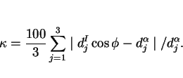
The lattice matching is expressed in terms of a mean percentage planar misfit ![]() . To calculate
. To calculate ![]() , it is assumed that the inclusion is facetted on a plane
, it is assumed that the inclusion is facetted on a plane ![]() , and that the ferrite deposits epitaxially with its plane
, and that the ferrite deposits epitaxially with its plane ![]() , with the corresponding rational directions
, with the corresponding rational directions ![]() and
and ![]() being inclined at an angle
being inclined at an angle ![]() to each other. The interatomic spacings
to each other. The interatomic spacings ![]() along three such directions within the plane of
epitaxy are examined to obtain (Bramfitt, 1970):
along three such directions within the plane of
epitaxy are examined to obtain (Bramfitt, 1970):
 |
(14) |
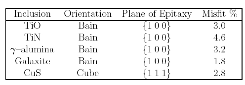 |
To enable the lattice matching concept to be compared with experiments, it is necessary not only to obtain the right orientation relationship, but the inclusion must also be facetted on the correct plane of epitaxy.
The idea of lattice matching stems originally from work on the solidification of aluminium melts inoculated with particles in order to produce grain refinement (see for example, Chart et al., 1975); as will be seen later, the extrapolation of this concept to solid state transformations is not entirely justified. It has even been suggested (Mills et al., 1987) that there may exist reproducible orientation relationships between inclusions and the ferrite plates that they nucleate. Experiments however, demonstrate the absence of a reproducible ferrite/inclusion orientation relationship (Dowling et al., 1986).
In boron-containing welds, Oh et al. (1991) found that titanium and zirconium additions both gave similar variations in microstructure as their respective concentrations were increased.
This is in spite of the fact that the titanium oxide is supposed to have a better crystallographic match when compared with the large misfit with zirconium oxide. Unfortunately, it had to be
assumed that the titanium oxide was TiO and the zirconium oxide ZrO![]() ; futhermore, their zirconium containing
welds also had substantial quantities of titanium, between 51 and 73 parts per million. Nevertheless, the basic idea is worth investigating further, but with a characterisation of the inclusions and
with better control over the weld chemistry.
; futhermore, their zirconium containing
welds also had substantial quantities of titanium, between 51 and 73 parts per million. Nevertheless, the basic idea is worth investigating further, but with a characterisation of the inclusions and
with better control over the weld chemistry.
The fact that the inclusions, which form in the liquid steel, are randomly orientated in space, and that the orientation relationship of acicular ferrite with the parent austenite is always found
to be of the KS/NW type, necessarily implies that the inclusion/ferrite orientation relation also has to be random Fig. 18. A contrary view is due to Kluken
et al. (1991), who claim that the ![]() -ferrite grains sometimes nucleate epitaxially with inclusions. In
those circumstances, the acicular ferrite will also bear an orientation relationship with the inclusions since it will be related to the
-ferrite grains sometimes nucleate epitaxially with inclusions. In
those circumstances, the acicular ferrite will also bear an orientation relationship with the inclusions since it will be related to the ![]() -ferrite via the austenite. Textural measurements have been cited in support of this hypothesis (Kluken et al. 1990).
-ferrite via the austenite. Textural measurements have been cited in support of this hypothesis (Kluken et al. 1990).
![\includegraphics[width=12cm]{Figa13.eps}](img127.png) |
Other ways in which inclusions may assist the formation of acicular ferrite include stimulation by thermal strains or by the presence of chemical heterogeneities in the vicinity of the
inclusion/matrix interface; see review by Farrar and Harrison (1987). Alternatively, the inclusions may simply act as inert sites for heterogeneous nucleation (Ricks et al., 1982; Barritte
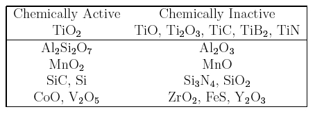
and Edmonds, 1982; Dowling et al., 1986). Chemical reactions are also possible at the inclusion matrix interface, as revealed by experiments in which pure ceramics were diffusion bonded to
steels (Strangwood & Bhadeshia, 1988). The diffusion bonded composite samples were then subjected to heat treatments in which the steel transforms from austenite to ferrite. By comparing
ferrite formation events at the ceramic/steel interface with those within the bulk of the steel, it was possible to identify the mechanism by which the ceramics influence ferrite nucleation. Chemical
reactions, the details of which depended on the particular ceramic tested, were found to be powerful stimulants for ferrite nucleation (Table 2). Although these experiments reveal a possible
mechanism for the interaction between nonmetallic particles and ferrite nucleation, only allotriomorphic ferrite (rather than acicular ferrite) could be studied because of the high alloy content of
the steels used. The results may not therefore be directly applicable to weld deposits. For example, ![]() is
widely believed to be a good nucleant for acicular ferrite, but is found in the context of the diffusion bonding experiments to be chemically inert.
is
widely believed to be a good nucleant for acicular ferrite, but is found in the context of the diffusion bonding experiments to be chemically inert.
 |
Although the plates of acicular ferrite which form first nucleate heterogeneously on the nonmetallic inclusions, subsequent plates can form autocatalytically. As pointed out earlier, it follows
that a one-to-one correspondence between plates of acicular ferrite and inclusions is not to be expected. However, it is difficult to establish this using metallography. By analogy with the procedure
used by Chart et al. (1975) for aluminium alloys, if the volume of a typical plate of acicular ferrite is taken to be ![]() , and that of a spherical inclusion
, and that of a spherical inclusion ![]() , then of all the grains examined, only 7.4% can be expected to display the
nucleating particle. Furthermore, the intercept of the particle in the section concerned may be much smaller then its diameter. The calculation presented by Chart et al. is valid when the
grains of the major phase are approximately spherical. It is necessary to allow for the anisotropy of shape in the case of acicular ferrite. If the acicular ferrite which contains an inclusion of
radius
, then of all the grains examined, only 7.4% can be expected to display the
nucleating particle. Furthermore, the intercept of the particle in the section concerned may be much smaller then its diameter. The calculation presented by Chart et al. is valid when the
grains of the major phase are approximately spherical. It is necessary to allow for the anisotropy of shape in the case of acicular ferrite. If the acicular ferrite which contains an inclusion of
radius ![]()
![]() , is
assumed to be of the shape of a square plate of side 10
, is
assumed to be of the shape of a square plate of side 10![]() m and thickness
m and thickness ![]()
![]() , then the ratio of the mean linear intercepts of the two
phases is given by
, then the ratio of the mean linear intercepts of the two
phases is given by ![]() (Myers, 1953; Mack, 1956). This means that about 13% of all the plates observed may be
expected to show the nucleating particles, assuming that the entire section of the acicular ferrite plate is observed in the sample. The calculation also assumes that each plate contains just one
inclusion, and more importantly, that each observed-inclusion is responsible for nucleating the plate in which it is found (i.e., it has not been circumstantially incorporated into the
plate).
(Myers, 1953; Mack, 1956). This means that about 13% of all the plates observed may be
expected to show the nucleating particles, assuming that the entire section of the acicular ferrite plate is observed in the sample. The calculation also assumes that each plate contains just one
inclusion, and more importantly, that each observed-inclusion is responsible for nucleating the plate in which it is found (i.e., it has not been circumstantially incorporated into the
plate).
If the volume fraction of acicular ferrite in the sample examined is large then it is not safe to assume that the observation of a particle in the plate implies that the particle is a nucleating centre. Recent work by Barbaro et al. (1990) claims that many of the acicular ferrite plates nucleate autocatalytically, since the number of nucleating inclusions in any acicular ferrite ``colony" was found to be less than the number of plates in that colony. The conclusion is however not safe since the percentage of plates containing inclusions was around 7-11%. On the other hand, given that there is an invariant-plane strain shape deformation accompanying transformation, it is very likely that some degree of autocatalysis does occur during the acicular ferrite transformation. By examining the orientation relationships between adjacent plates in clusters of acicular ferrite plates, it has been possible to demonstrate that such plates have a similar orientation in space (Yang & Bhadeshia, 1989a). Furthermore, the proportion of plates having similar orientations is found to be larger than expected from a knowledge of the austenite/ferrite orientation relationship. This could be taken as evidence for autocatalytic nucleation.
While the theory capable of ranking different kinds of nonmetallic inclusions in terms of their effectiveness in nucleating acicular ferrite does not exist, there is considerable circumstantial
evidence that titanium oxides (TiO, Ti![]() O
O![]() , TiO
, TiO![]() ) are very potent in this respect, and that Al
) are very potent in this respect, and that Al![]() O
O![]() is not. Titanium nitride also appears to be effective in nucleating acicular
ferrite, but is less stable at high temperatures when compared with titanium oxide. The problem is complicated by the fact that most welds, and indeed, wrought steels, contain aluminium which in
general is a stronger oxide former than titanium. Consequently, it is the alumina which forms first in the melt, followed by titania, which often grows as a thin coating on the alumina particles.
Thus, there has to be available sufficient oxygen to first tie up the aluminium, and then to combine with the titanium (Horii et al., 1986; 1988). The concentration of oxygen required
therefore depends on the level of aluminium, which should be minimal in steels designated for acicular ferrite microstructures. This is the reason why Ringer et al. (1990) were unable to
detect titanium oxides in titanium containing steels which had low oxygen concentrations and enough aluminium to combine with that oxygen.
is not. Titanium nitride also appears to be effective in nucleating acicular
ferrite, but is less stable at high temperatures when compared with titanium oxide. The problem is complicated by the fact that most welds, and indeed, wrought steels, contain aluminium which in
general is a stronger oxide former than titanium. Consequently, it is the alumina which forms first in the melt, followed by titania, which often grows as a thin coating on the alumina particles.
Thus, there has to be available sufficient oxygen to first tie up the aluminium, and then to combine with the titanium (Horii et al., 1986; 1988). The concentration of oxygen required
therefore depends on the level of aluminium, which should be minimal in steels designated for acicular ferrite microstructures. This is the reason why Ringer et al. (1990) were unable to
detect titanium oxides in titanium containing steels which had low oxygen concentrations and enough aluminium to combine with that oxygen.
In order to simplify the problem of oxide (or nitride) formation, it is usual to assume that the stronger oxide forming element is the first to react with oxygen, followed by the weaker oxide
forming element. This assumption is based on the magnitude of the free energy change accompanying the oxidation of the free element. It can lead to difficulties. As emphasised earlier, titanium oxide
is supposed to be thermodynamically more stable than the titanium nitride, and yet the latter is often the first to grow from the liquid phase:
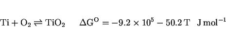 |
(15) |
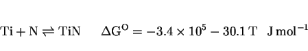 |
(16) |
These apparent contradictions could be attributed to kinetic effects, but they could also arise because the stabilities of the oxides are assessed using free energy data which are standardised for the reaction of each metallic element with one mole of oxygen, the oxide and the pure element having unit activities. It is unlikely that this method correctly represents the real situation where all the reactants and products activities are far from unity. The ranking of the oxide stabilities can change as a function of the actual concentrations of the reactants. Nevertheless, in the absence of any suitable model capable of predicting the reactivities of the variety of elements in liquid solution with oxygen, the best working hypothesis must assume that they react in accordance with an intuitive order of oxidising potential. For welds, this usually means that aluminium has the first `bite' at the available oxygen, followed by titanium, as was assumed by Horii et al. (1986; 1988) in their study of submerged arc weld deposits.
As stated earlier, excessive aluminium can tie up the available oxygen and prevent the titanium from forming oxides. A further advantage of minimising the aluminium content is that a smaller oxygen concentration can then be used to achieve the same titanium effect, thereby reducing the inclusion content in the steel. Any free nitrogen, which may combine with the titanium to form a nitride, should also be controlled, perhaps by adding boron as a nitrogen getering agent. Experiments have revealed that trace elements like calcium, and rare earth elements like cerium, at the concentrations used typically for inclusion shape control in wrought alloys, have no detectable influence on the development of the acicular ferrite microstructure (Horii et al., 1986; 1988). Such elements may be incorporated from the fused base plate into the weld deposit, especially during high heat input welding which leads to considerable dilution effects (Fig. 19). Continuously cast steels which are aluminium killed are a potent source of aluminium for welds in which the degree of dilution is large.
One difficulty as far as welds are concerned, is that the small amount of aluminium that remains in solid solution, as opposed to that which combines with oxygen, does not seem to correlate well
with the total aluminium or oxygen concentration (Thewlis, 1989a, b). For reasons which are not clear, small concentrations of dissolved aluminium seem to promote the formation of Widmanstätten
ferrite, which is a nuisance when attempts are being made to design microstructures which are essentially acicular ferrite. The effect manifests itself particularly in the as-deposited microstructure
of self-shielded arc welds (SSAW) which usually exhibits a small volume fraction of acicular ferrite but an exaggerated amount of Widmanstätten ferrite (Abson, 1987b; Grong et al.,
1988). In the SSAW process, the pool has little or no protection by any shielding gas; it is instead, deoxidised by the large aluminium concentration in the electrode, the deposit ending up with more
than 0.5 wt.% of aluminium and only about 120 p.p.m. of oxygen. The lack of acicular ferrite has been attributed to the low oxygen concentration, but on the other hand, it is the
Widmanstätten ferrite which forms first, leaving little residual austenite available for subsequent transformation to acicular ferrite. The propensity to form Widmanstätten ferrite in
self-shielded arc welds correlates with their large concentration of aluminium in solid solution. ![]()
It has been reported that the mean size of nonmetallic inclusions in welds increases with the overall aluminium concentration (Thewlis, 1989a), but the observed variations are in fact rather small and Evans (1990) has demonstrated that very large changes in aluminium concentration at constant oxygen concentration cause negligible variations in the mean inclusion diameter. The factors influencing inclusion size are not understood in detail, and although inclusions are sometimes regarded as a panacea for improved weld microstructure, their ability to nucleate cleavage and ductile failure must also be appreciated. These contradicting requirements call for a compromise level of inclusions, but it seems likely that current weld deposits contain excessive oxygen concentrations, well beyond the levels needed to induce the intragranular nucleation of ferrite. For example, oxygen concentrations less than 120 p.p.m. are established to be adequate in producing an acicular ferrite microstructure in wrought alloys. The problem is likely to become more prominent in the near future, as strength levels increase and toughness therefore becomes more sensitive to the presence of nonmetallic particles.
The character of inclusions also alters as the aluminium concentration rises, the oxide particles being predominantly MnOSiO![]() at low Al content, and then changing to a mixed spinel oxide (Al
at low Al content, and then changing to a mixed spinel oxide (Al![]() O
O![]() MnO) and finally to
MnO) and finally to ![]() -Al
-Al![]() O
O![]() (Thewlis, 1990). It is believed that the aluminium to oxygen
ratio should be such as to favour the formation of galaxite, although the ratio itself is difficult to estimate for multicomponent systems containing strong deoxidisers other than aluminium and
because the soluble concentration of Al etc. cannot be calculated.
(Thewlis, 1990). It is believed that the aluminium to oxygen
ratio should be such as to favour the formation of galaxite, although the ratio itself is difficult to estimate for multicomponent systems containing strong deoxidisers other than aluminium and
because the soluble concentration of Al etc. cannot be calculated.
![\includegraphics[width=12cm]{Figa14.eps}](img149.png) |
It is sometimes argued that manganese sulphide (MnS) is a prerequisite for the intragranular nucleation of ferrite, but recent experiments (Ringer et al., 1990) reveal that Ti![]() O
O![]() particles are effective even in the
absence of MnS surface films, or of any detectable manganese depletion in the austenite near the particles.
particles are effective even in the
absence of MnS surface films, or of any detectable manganese depletion in the austenite near the particles.
Naturally, any manganese depletion caused by the precipitation of its sulphide can only help the nucleation of ferrite. It has been demonstrated conclusively that depletion zones are indeed to be found in the vicinity of MnS which precipitates from austenite, but that the zones are rapidly homogenised soon after the precipitation is completed (Mabuchi et al., 1996). The MnS is therefore only active in stimulating ferrite nucleation if the latter occurs shortly after MnS formation. Any prolonged holding in the austenite phase field homogenises the manganese concentration. For the same reason, MnS particles might be active as heterogeneous nucleation sites on the first occasion that they precipitate, but their potency is reduced if the sample is then reheated into the austenite phase field. This has significant implications for the large number of experiments based on reheated weld metals.
Although this review is concerned largely with weld deposits, there is a lot to be learned from recent advances in the production of wrought acicular ferrite steels with controlled oxide
additions. The oxide particles in wrought acicular ferrite steels have a diameter of about 2![]() , and are
introduced during steel making. The oxide particles thought to be effective in nucleating acicular ferrite are believed to be
, and are
introduced during steel making. The oxide particles thought to be effective in nucleating acicular ferrite are believed to be ![]() , although each inclusion is usually a complex combination of the titanium compounds and
phases such as MnS,
, although each inclusion is usually a complex combination of the titanium compounds and
phases such as MnS, ![]() , (Mn,Si)O, etc., in both crystalline and amorphous conditions. The aluminium concentration
of the steel has to be minimal
, (Mn,Si)O, etc., in both crystalline and amorphous conditions. The aluminium concentration
of the steel has to be minimal ![]() during steelmaking since the formation of Ti-oxides is otherwise prevented (Nishioka and
Tamehiro, 1988). This is confirmed by the detailed studies of Imagumbai et al. (1985), who measured the microstructure of a large number of wrought steels together with the soluble aluminium
concentration and the oxide particle densities. They demonstrated that there is a strong effect of dissolved aluminium on the microstructure, with the volume fraction of acicular ferrite obtained
decreasing rapidly at concentrations greater than about 70 p.p.m. (Fig. 20a). An interesting result from their work is that the effect of inclusions in
enhancing the formation of acicular ferrite was found to saturate at about 120 p.p.m. of oxygen, although this limiting value must also depend on the heat treatment and the details of the other
phases present in the steel (Fig. 20b). For example, it is obvious from their work, that the austenite grain size has to be large in order to favour the
formation of substantial amounts of acicular ferrite, consistent with the results of Yang and Bhadeshia (1987b). The most critical region of the heat affected zone of welds is the region nearest the
fusion zone, where the austenite grain structure is very coarse, and in this respect, the inoculated steels are ideal since the coarse grains transform readily to acicular ferrite. It is interesting
to note (as pointed out by Imagumbai et al.) that the oxygen concentration of these steels (
during steelmaking since the formation of Ti-oxides is otherwise prevented (Nishioka and
Tamehiro, 1988). This is confirmed by the detailed studies of Imagumbai et al. (1985), who measured the microstructure of a large number of wrought steels together with the soluble aluminium
concentration and the oxide particle densities. They demonstrated that there is a strong effect of dissolved aluminium on the microstructure, with the volume fraction of acicular ferrite obtained
decreasing rapidly at concentrations greater than about 70 p.p.m. (Fig. 20a). An interesting result from their work is that the effect of inclusions in
enhancing the formation of acicular ferrite was found to saturate at about 120 p.p.m. of oxygen, although this limiting value must also depend on the heat treatment and the details of the other
phases present in the steel (Fig. 20b). For example, it is obvious from their work, that the austenite grain size has to be large in order to favour the
formation of substantial amounts of acicular ferrite, consistent with the results of Yang and Bhadeshia (1987b). The most critical region of the heat affected zone of welds is the region nearest the
fusion zone, where the austenite grain structure is very coarse, and in this respect, the inoculated steels are ideal since the coarse grains transform readily to acicular ferrite. It is interesting
to note (as pointed out by Imagumbai et al.) that the oxygen concentration of these steels (![]() p.p.m.) is comparable with that of normal fully killed steel (which usually contains aluminium oxides), so that any detrimental effect of inclusions in helping fracture is not
exaggerated for the inoculated steels.
p.p.m.) is comparable with that of normal fully killed steel (which usually contains aluminium oxides), so that any detrimental effect of inclusions in helping fracture is not
exaggerated for the inoculated steels.
![\includegraphics[width=12cm]{soluble.eps}](img154.png) |
Experimental measurements indicate that the procedure is very successful in enhancing the toughness of the critical regions of the HAZ's of welds under both laboratory and commercial conditions. It is worth emphasising that the design of such steels also requires that the alloy chemistry be adjusted to avoid the prior formation of excessive quantities of phases such as allotriomorphic ferrite, Widmanstätten ferrite, etc., so as to leave enough untransformed austenite available for the formation of an effective quantity of intragranularly nucleated acicular ferrite. As discussed by Nishioka and Tamehiro (1988), this can be accomplished by the careful use of microalloying elements such as Nb, Mo and B, thereby avoiding a large rise in the carbon equivalent of the steel. Boron should be avoided for critical applications, since its effects are sometimes difficult to control.
It is known that in some circumstances, very small concentrations of titanium (![]() p.p.m.) can be a stimulus
for acicular ferrite. Some elegant experiments by Ichikawa et al. (1994a) have revealed that the role of titanium in these cases is not to provide titanium oxide or nitride substrates, but
more to foster a transition from glassy Si/Mn rich oxides to crystalline manganese and aluminium rich galaxite (
p.p.m.) can be a stimulus
for acicular ferrite. Some elegant experiments by Ichikawa et al. (1994a) have revealed that the role of titanium in these cases is not to provide titanium oxide or nitride substrates, but
more to foster a transition from glassy Si/Mn rich oxides to crystalline manganese and aluminium rich galaxite ( ![]() ). The small amount of titanium shows up when the inclusions are microanalysed, but not as a
separate phase.
). The small amount of titanium shows up when the inclusions are microanalysed, but not as a
separate phase.
We have seen that the aluminium concentration influences the formation of titanium oxides because of its stronger affinity for oxygen. Although silicon has a weaker affinity for oxygen than aluminium, it still has a significant bearing on the amount of oxygen available to form titanium oxide (Lee and Pan, 1992a). It is found that in wrought steels, an increase in the silicon concentration in the molten steel leads to a decreased in the available oxygen concentration, and consequently promotes the formation of titanium nitrides at the expense of titanium oxides. This in turn leads to a deterioration of the microstructure (a reduction in the acicular ferrite content) since TiN particles are effective in preventing austenite grain growth in the heat affected zone.
It is of interest to examine a recent attempt at inducing the intragranular nucleation of allotriomorphic ferrite using nonmetallic inclusions (Ochi et al., 1988). The steel concerned had
a relatively high sulphur concentration (![]()
![]() ) in order to precipitate a fine dispersion of MnS particles. A small vanadium addition
) in order to precipitate a fine dispersion of MnS particles. A small vanadium addition ![]() then led to the precipitation of vanadium nitride on the sulphides, which in turn provided
the sites for the subsequent formation of vanadium carbides. The carbides were then found to act as substrates for the intragranular nucleation sites for ferrite. This particular sequence of events
seems tortuous and remarkable, but has been demonstrated rigorously by Ochi et al., although the reason why vanadium carbide is effective in nucleating ferrite is not obvious. Whether a
similar sequence can be of use in nucleating acicular ferrite remains to be seen, although high levels of sulphur are usually not tolerated in steel weld deposits.
then led to the precipitation of vanadium nitride on the sulphides, which in turn provided
the sites for the subsequent formation of vanadium carbides. The carbides were then found to act as substrates for the intragranular nucleation sites for ferrite. This particular sequence of events
seems tortuous and remarkable, but has been demonstrated rigorously by Ochi et al., although the reason why vanadium carbide is effective in nucleating ferrite is not obvious. Whether a
similar sequence can be of use in nucleating acicular ferrite remains to be seen, although high levels of sulphur are usually not tolerated in steel weld deposits.
Yamamoto et al. (1987) have made the claim that it is the MnS, which grows on the titanium oxide long after solidification, that is really responsible for the nucleation of acicular
ferrite. Consistent with this, their microanalysis data indicated that the oxide particles usually contain about 10 wt.% of manganese, and that the lack of sulphur (![]() wt.%) in the steel reduced the fraction of acicular ferrite that formed. A contradictory result has been reported by Chijiiwa et
al. (1988), that a reduction of sulphur concentration from 0.005 to 0.001 wt.% tends to decrease the amount of allotriomorphic ferrite and promote the formation of acicular ferrite. Furthermore,
Evans (1986) found that an increase in the amount of MnS in nonmetallic inclusions entrapped in steel weld metals leads to a decrease in the volume fraction of acicular ferrite. Ringer et
al. (1990) also found that Ti
wt.%) in the steel reduced the fraction of acicular ferrite that formed. A contradictory result has been reported by Chijiiwa et
al. (1988), that a reduction of sulphur concentration from 0.005 to 0.001 wt.% tends to decrease the amount of allotriomorphic ferrite and promote the formation of acicular ferrite. Furthermore,
Evans (1986) found that an increase in the amount of MnS in nonmetallic inclusions entrapped in steel weld metals leads to a decrease in the volume fraction of acicular ferrite. Ringer et
al. (1990) also found that Ti![]() O
O![]() particles without any surrounding MnS films can nevertheless be effective in the intragranular nucleation of ferrite. Following an assessment of the literature on inclusions in weld
deposits, Abson (1987a) considered that the presence of MnS at the surface of oxide particles inhibits the nucleation of ferrite, and furthermore, that the addition of elements which getter sulphur
makes the inclusions more effective. Ichikawa et al. (1994a) in careful experiments have shown minute manganese sulphides on nonmetallic inclusions are ineffective as ferrite nucleants.
particles without any surrounding MnS films can nevertheless be effective in the intragranular nucleation of ferrite. Following an assessment of the literature on inclusions in weld
deposits, Abson (1987a) considered that the presence of MnS at the surface of oxide particles inhibits the nucleation of ferrite, and furthermore, that the addition of elements which getter sulphur
makes the inclusions more effective. Ichikawa et al. (1994a) in careful experiments have shown minute manganese sulphides on nonmetallic inclusions are ineffective as ferrite nucleants.
An interesting study by Umemoto et al. (1986) has revealed that quite small concentrations of sulphur (![]() wt.%) can in some circumstances lead to an enhancement in the nucleation rate of bainite. It seems that when the austenitising temperature is sufficiently low, the sulphur tends
to precipitate at the austenite grain boundaries in the form of iron rich sulphides. These in turn promote the nucleation of bainite. Umemoto et al. noted that steels austenitised at an
elevated temperature, and subsequently held at a lower temperature (apparently still in the austenite phase field), precipitate a very small volume fraction of cementite particles at the austenite
grain boundaries. They also stimulate the nucleation of bainite. These results are difficult to understand if the two austenitisation heat treatments are confined strictly to the single phase
austenite fields. For example, the cementite particles were found at the austenite grain boundaries of a Fe-0.61C wt.% alloy, after quenching from 1200
wt.%) can in some circumstances lead to an enhancement in the nucleation rate of bainite. It seems that when the austenitising temperature is sufficiently low, the sulphur tends
to precipitate at the austenite grain boundaries in the form of iron rich sulphides. These in turn promote the nucleation of bainite. Umemoto et al. noted that steels austenitised at an
elevated temperature, and subsequently held at a lower temperature (apparently still in the austenite phase field), precipitate a very small volume fraction of cementite particles at the austenite
grain boundaries. They also stimulate the nucleation of bainite. These results are difficult to understand if the two austenitisation heat treatments are confined strictly to the single phase
austenite fields. For example, the cementite particles were found at the austenite grain boundaries of a Fe-0.61C wt.% alloy, after quenching from 1200![]() C.
C.
There are evidently, major problems in reaching any conclusions about the role of sulphur in inducing the formation of acicular ferrite. Nevertheless, the notion that manganese sulphide is potent
in nucleating ferrite is attractive from a commercial point of view, because it is in any case a common impurity in steels. However, in normal circumstances it precipitates in the solute-enriched
interdendritic regions of the solidification microstructure, regions which are rich in manganese and hence have a relatively low tendency to transform to ferrite. The ability of any MnS to act as the
heterogeneous nucleation site for ferrite is then reduced by the locally large concentration of austenite stabilising elements in the interdendritic regions. To overcome this difficulty, Ueshima
et al. (1989) systematically studied methods of producing more uniform distributions of MnS particles, by inducing the sulphide particles to nucleate on oxide particles which grow in the liquid
phase and are trapped more or less uniformly by the advancing solidification front. High purity melts, each containing 0.004 wt.% of sulphur, were deoxidised using one of Al, Ti, Zr, La, Ce, Hf or Y.
Of these, aluminium and titanium additions were found to be the most uniformly dispersed and insensitive to the killing time within the range 30-600![]() s (Fig. 21). All of the deoxidising elements studied were able to promote MnS nucleation (Fig. 21), but Ti
s (Fig. 21). All of the deoxidising elements studied were able to promote MnS nucleation (Fig. 21), but Ti![]() O
O![]() and zirconia were particularly effective, with aluminium being the least potent in this respect. The MnS precipitated during solid-state transformation over a temperature range estimated to
be 1050-1400
and zirconia were particularly effective, with aluminium being the least potent in this respect. The MnS precipitated during solid-state transformation over a temperature range estimated to
be 1050-1400 ![]() C. Whilst these results do not help clarify the role of sulphides in stimulating ferrite
nucleation, they establish the methods of controlling the sulphide precipitation. Ueshima et al. did estimate using diffusion theory that the formation of MnS would lead to a manganese
depleted zone in its close proximity of the precipitate, a zone in which the tendency to form ferrite would be enhanced. There are however, contradictory experimental data which suggest the absence
of such zones (Barritte et al., 1982; Lee and Pan, 1992b). Direct confirmation of the role of sulphides as ferrite nucleating agents is now needed, but even if the role is found to be
positive, great care will have to be exercised to avoid the potent grain boundary embrittling effect of sulphur.
C. Whilst these results do not help clarify the role of sulphides in stimulating ferrite
nucleation, they establish the methods of controlling the sulphide precipitation. Ueshima et al. did estimate using diffusion theory that the formation of MnS would lead to a manganese
depleted zone in its close proximity of the precipitate, a zone in which the tendency to form ferrite would be enhanced. There are however, contradictory experimental data which suggest the absence
of such zones (Barritte et al., 1982; Lee and Pan, 1992b). Direct confirmation of the role of sulphides as ferrite nucleating agents is now needed, but even if the role is found to be
positive, great care will have to be exercised to avoid the potent grain boundary embrittling effect of sulphur.
![\includegraphics[width=12cm]{Figa16.eps}](img163.png) |
Finally, it is worth mentioning the research by Nakanishi et al. (1983) on role of oxysulphides in wrought steels. In the heat-affected zone of steels containing titanium nitride, the nitride dissolves in the immediate proximity of the fusion boundary, leading to a detrimental coarse austenite grain structure. Nakanishi et al. demonstrated that a combined treatment with titanium nitride and calcium oxysulphides prevents the heat-affected zone grain coarsening because the oxysulphides are stable to very high temperatures.
There has been considerable recent interest in the addition of traces of the rare-earth elements (cerium, neodymium, lanthanum and yttrium) to steels in order to enhance their hardenability (Jingsheng et al., 1988). Attention has been focused on cerium additions of up to 0.15 wt.%, where it is found that the transformation kinetics for allotriomorphic ferrite formation are retarded to a greater extent than for bainite formation. The mechanism is believed to be similar to that of boron, involving segregation to the austenite grain boundaries. The analogy with boron is reinforced by the observation that cerium has little effect on the acicular ferrite transformation (Horii et al., 1986; 1988). Thus, it appears that cerium and boron both retard the allotriomorphic ferrite reaction to a much greater extent than the bainite reaction. The effect of cerium is reduced drastically if the phosphorus content exceeds 0.02 wt.%, although the mechanism of this interaction has yet to be established.
A further indirect role of elements such as yttrium arises from their ability to getter sulphur, especially if the presence of sulphides influences the nucleation frequency of ferrite (Abson, 1987a).
Caution is obviously necessary in using sulphur as an alloying addition, because of its well established role in embrittling steels. At the same time, it is possible to envisage circumstances where the embrittlement could be more than compensated by a general improvement in microstructure. Thus, Lee and Pan (1992b) have reported an improvement in toughness as the sulphur concentration is raised from 0.0005 to within the range 0.005-0.01 wt.%, due to its effect on increasing the acicular ferrite content of the microstructure. Their experiments established that some of the sulphur segregates to the austenite grain boundaries and hence increases the hardenability of the steel, since segregation must reduce the grain boundary energy. Consequently, the amount of allotriomorphic ferrite is reduced and there is a corresponding increase in the acicular ferrite content, together with an improvement in toughness.
Further increases in sulphur concentration caused an increase in the precipitation of sulphides at the austenite grain boundaries. The precipitates enhanced the nucleation rate of allotriomorphic ferrite at the austenite grain surfaces and hence led to a deterioration of mechanical properties. There is therefore an optimum sulphur concentration.
It is probable that this mechanism of property improvement is only useful in steels which contain inclusions suitable for acicular ferrite nucleation. The mechanism of microstructure improvement is after all based on the relative potency of austenite grain surface and intragranular nucleation sites. Consistent with this, variations in sulphur concentration in the range 0.002-0.006 wt.% do not appear to have any effect on the properties of the heat affected zone of steels without acicular ferrite (Konkol, 1987).
Nitrogen is not usually a deliberate alloying addition in most low-alloy steel weld deposits. It is picked up from the environment and from impurities in the consumables used in the welding
process. In situations where the weld is diluted by the parent plate, the composition of the plate must also influence the nitrogen concentration in the weld. Although the concentration of nitrogen
is generally kept rather small (![]() -120 p.p.m.) it is known to have a potent detrimental effect on the
toughness of the weld. The mechanism of embrittlement is believed to be associated with strain age-hardening (Lancaster, 1987; Keown et al., 1976; Judson and McKeown, 1982; Oldland, 1985).
This, combined with solid-solution hardening causes an increase the yield stress of the weld without modifying the microstructure, and consequently cause a decrease in the toughness.
-120 p.p.m.) it is known to have a potent detrimental effect on the
toughness of the weld. The mechanism of embrittlement is believed to be associated with strain age-hardening (Lancaster, 1987; Keown et al., 1976; Judson and McKeown, 1982; Oldland, 1985).
This, combined with solid-solution hardening causes an increase the yield stress of the weld without modifying the microstructure, and consequently cause a decrease in the toughness.
Nitrogen is a diatomic gas, so that its activity in liquid steel (![]() ) varies according to Sievert's law, with the
square root of the partial pressure of nitrogen (
) varies according to Sievert's law, with the
square root of the partial pressure of nitrogen (![]() ) in the gas which is in equilibrium with the liquid steel
(Phelke and Eliott, 1960):
) in the gas which is in equilibrium with the liquid steel
(Phelke and Eliott, 1960):
 |
(17) |
 |
(18) |
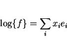 |
(19) |
If it is assumed that the amount of nitrogen found in the weld at ambient temperature is to some extent related directly to its solubility in liquid steel, then the above method should provide a crude way of rationalising the effect of weld chemistry on the nitrogen content of the welds. An approach like this has been used successfully for gas metal arc welding of steels in a nitrogen atmosphere (Kobayanshi et al., 1972). It has recently been applied with moderate success to manual metal arc (including iron-powder electrodes) and submerged arc welds, Fig. 22 (Bhadeshia et al., 1988). The accuracy of relating weld nitrogen concentration to the weld pool chemistry and to the nitrogen content of the consumables and parent plate must of course be limited. For example, variations in arc length, during manual metal arc welding, can easily lead to substantial corresponding variations in the weld nitrogen content. The method for estimating the nitrogen concentration is nonetheless useful in indicating overall trends.
![\includegraphics[width=12cm]{Figa17.eps}](img174.png) |
The effect of nitrogen on the development of microstructure in low-alloy steel welds has until recently been difficult to understand, especially in the context of welds containing titanium and boron as deliberate alloying additions. Some studies (Mori et al., 1981; Kawabata et al., 1986) indicated that nitrogen has no detectable influence on the acicular ferrite content of welds, whereas others (Okabe et al., 1983; Ito and Nakanishi, 1975) indicated alterations in microstructure as a function of the nitrogen concentration. Given that weld nitrogen concentrations are rarely out of the range 0.004-0.020 wt.%, nitrogen is hardly expected to have any significant thermodynamic effect on the stability of the the parent and product phases. Any effect must therefore largely be kinetic, due to for example, the combination of nitrogen with boron (which has a large effect on kinetics at relatively small concentrations).
The difficulties have to a significant extent been resolved recently with a series of careful experiments by Horii et al. (1986; 1988) and Lau et al. (1987; 1988), who studied titanium, boron, nitrogen phenomena in submerged arc welds. The essence of their conclusions is that nitrogen is not expected to influence the development of microstructure in the absence of boron additions. The situation is found to be quite different when boron is added with the intention of improving hardenability and hence enhancing the opportunity for the austenite to transform into acicular ferrite rather than less desirable phases such as allotriomorphic and Widmanstätten ferrite. Titanium, which is a strong oxide and nitride forming element, is usually added in order to protect the boron from oxidation during transfer across the arc. It also has the key role of preventing the boron from combining with nitrogen in order to form boron nitride. Boron is only effective in improving hardenability if it remains in solid solution in the austenite, since it is a misfitting atom in the austenite lattice and hence segregates to the austenite grain surfaces. This reduces the austenite grain boundary energy thereby making the boundaries less potent heterogeneous ferrite nucleation sites. Boron in the form of nitrides or carbides at the austenite grain surfaces can in fact reduce hardenability since the particles seem to induce the nucleation of ferrite. An excess of soluble boron tends to combine with carbon to form boron carbides which are known to be detrimental towards toughness (Dan and Gunji, 1984; Habu, 1978).
It is now recognised that for a given oxygen and boron concentration, the aluminium and titanium concentration (and that of any other oxide former) has to be large enough to combine with all the available oxygen. Furthermore, there has to be enough titanium left over to combine with any nitrogen so as to leave the boron free to segregate to the austenite grain surfaces. If these conditions are not satisfied, then nitrogen in effect renders the boron useless and leads to a deterioration in microstructure.
A way for making rational decisions during the design of titanium and boron containing deposits could therefore be based on a methodology in which the oxidation reactions are phenomenologically carried out in a sequence consistent with the thermodynamic stability of the elements (Fig. 23).
![\includegraphics[width=12cm]{Figa18.eps}](img175.png) |
The difficulties of doing this are illustrated by the work of Kluken and Grong (Kluken and Grong, 1989), whose ideas are reproduced below in a more explicit manner. The total volume fraction ![]() of inclusions is given approximately by (Franklin, 1982):
of inclusions is given approximately by (Franklin, 1982):
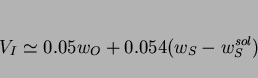 |
(20) |
 |
(21) |
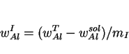 |
(22) |
![\begin{displaymath}\log\{[w_{Ti}^{sol}][w_N^{sol}]\} = {8000\over T} + 0.32 \end{displaymath}](img187.png) |
(23) |
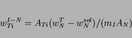 |
(24) |
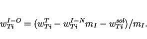 |
(25) |
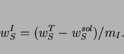 |
(26) |
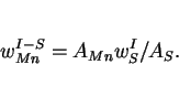 |
(27) |
 |
(28) |
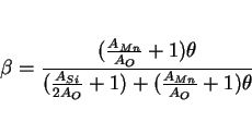 |
(29) |
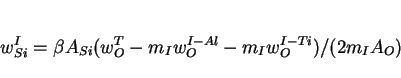 |
(30) |
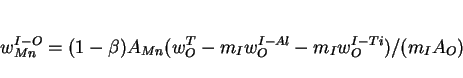 |
(31) |
The calculations presented above cannot be carried out without a knowledge of the Al, Ti and S concentrations in solid solution, and as already pointed out, are subject to numerous approximations.
This implicitly includes the assumption that the oxidation state of the titanium is known. Titanium compounds such as TiN, TiC and TiO have similar lattice parameters and crystal structures; they are
consequently difficult to distinguish using diffraction methods. Common microanalytical techniques (such as energy dispersive X-ray analysis) clearly identify the presence of titanium, but unless
windowless detectors are used, the light elements cannot be detected. Even when oxygen can be detected, the results are difficult to quantify since absorption corrections for the X-rays are difficult
due to the shape and unknown thickness of the particles. Therefore, the oxidation state and the factors controlling it, is not well established. Lau et al. assumed that the Ti is in the form
of TiO![]() whereas Kluken and Grong assumed it to be combined as Ti
whereas Kluken and Grong assumed it to be combined as Ti![]() O
O![]() . Abson (1987a) on the other hand, assumes that in weld deposits, the titanium
oxide is TiO. The major weakness, however, is the method for the partitioning of oxygen between the different metallic elements. It can for example, easily be demonstrated that manganese and silicon
oxides are found in systems where no oxygen is expected to remain after combining with Al and Ti. Furthermore, the silicon concentration has been known to influence the ability of titanium to combine
with oxygen (Lee and Pan, 1992a).
. Abson (1987a) on the other hand, assumes that in weld deposits, the titanium
oxide is TiO. The major weakness, however, is the method for the partitioning of oxygen between the different metallic elements. It can for example, easily be demonstrated that manganese and silicon
oxides are found in systems where no oxygen is expected to remain after combining with Al and Ti. Furthermore, the silicon concentration has been known to influence the ability of titanium to combine
with oxygen (Lee and Pan, 1992a).
The sequence of reactions outlined above should in principle determine the microstructure of the inclusions, with the compounds which form first being located near to the cores of the particles
(Fig. 24). Thus, the elements which are least reactive should be concentrated at the inclusion surface. This is consistent with the fact that the nonmetallic
particles found in some submerged arc weld deposits consist of titanium nitride cores, surrounded by a glassy phase containing manganese, silicon and aluminium oxides, with a thin layer of manganese
sulphide partly covering the surface of the inclusions (Barbaro et al., 1988). Similarly, in a weld containing negligible quantities of aluminium or titanium (![]() p.p.m), the inclusion core was found to consist of MnO-SiO
p.p.m), the inclusion core was found to consist of MnO-SiO![]() whereas the addition of some 40 p.p.m. of aluminium led to the presence of some alumina in the core (Es-Souni and Beaven, 1990). On the other hand, both these investigations suggested
that in welds containing titanium in addition to Al, Mn and Si, some titanium oxide (or other titanium compounds - the detailed chemistry could not be resolved) could be found at the particle
surfaces, a result which is inconsistent with the strong deoxidising potential of titanium, and one which suggests that the titanium oxide formed at a late stage in the inclusion growth process. This
conclusion seems unlikely; an alternative explanation is that the main body of the inclusions (consisting of manganese and silicon oxides) nucleates and grows on the titanium compound, but that the
degree of wetting with the substrate is small so that the other oxides do not succeed in engulfing the titanium compounds.
whereas the addition of some 40 p.p.m. of aluminium led to the presence of some alumina in the core (Es-Souni and Beaven, 1990). On the other hand, both these investigations suggested
that in welds containing titanium in addition to Al, Mn and Si, some titanium oxide (or other titanium compounds - the detailed chemistry could not be resolved) could be found at the particle
surfaces, a result which is inconsistent with the strong deoxidising potential of titanium, and one which suggests that the titanium oxide formed at a late stage in the inclusion growth process. This
conclusion seems unlikely; an alternative explanation is that the main body of the inclusions (consisting of manganese and silicon oxides) nucleates and grows on the titanium compound, but that the
degree of wetting with the substrate is small so that the other oxides do not succeed in engulfing the titanium compounds.
![\includegraphics[width=6cm]{Figa19.eps}](img202.png) |
In weld deposits, acicular ferrite is one of the last transformation products to form after the growth of allotriomorphic and Widmanstätten ferrite. As a consequence, it is bound to be influenced by prior transformation products. Indeed, its volume fraction during continuous cooling transformation of such welds can often be estimated simply from a calculation of the volume fractions of allotriomorphic and Widmanstätten ferrite, and the assumption (in equation 12) that the remainder of the austenite transforms to acicular ferrite (Bhadeshia et al., 1985a). For the same reason, it is found that in wrought alloys with mixed microstructures, the amount of acicular ferrite decreases with the austenite grain size, as grain boundary nucleated phases such as allotriomorphic ferrite become more dominant (Barbaro et al., 1988). The dependence of the volume fraction of acicular ferrite on the austenite grain size becomes less pronounced as the cooling rate (from the austenite phase field) is increased, since at slow cooling rates, much of the austenite is consumed during the higher temperature formation of allotriomorphic ferrite.
This dependence of the acicular ferrite content on the austenite grain size, in a mixed microstructure of acicular ferrite and allotriomorphic ferrite, can for isothermal reaction be expressed
precisely with the help of the following relationship:
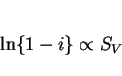 |
(32) |
An interesting observation reported by Dallum and Olson (1989) is that in samples containing mixtures of allotriomorphic ferrite, Widmanstätten ferrite and acicular ferrite, a relatively
small austenite grain size leads to a coarser acicular ferrite microstructure. They attributed this to a reduction in the ![]() nucleation rate, caused by some unspecified interaction with the prior transformation products (
nucleation rate, caused by some unspecified interaction with the prior transformation products (![]() and
and ![]() ). The likely explanation is that with a smaller austenite grain size, the volume fractions of
). The likely explanation is that with a smaller austenite grain size, the volume fractions of ![]() and
and ![]() that form are correspondingly
larger, thereby causing a larger degree of carbon enrichment in the residual austenite. This could lead to a reduction in the acicular ferrite nucleation rate and hence permit the fewer plates that
form to develop into larger particles before they collide with each other and stop growing.
that form are correspondingly
larger, thereby causing a larger degree of carbon enrichment in the residual austenite. This could lead to a reduction in the acicular ferrite nucleation rate and hence permit the fewer plates that
form to develop into larger particles before they collide with each other and stop growing.
Effects like these are of crucial importance in the development of mixed microstructures, but the coarsening of acicular ferrite per se is unlikely to lead to any drastic changes in the strength of weld deposits (Bhadeshia et al., 1989a,b). This is because the mean slip distance in a plate does not change very much as the plate becomes larger. Of course, it remains to be demonstrated whether toughness is sensitive to small variations in the size and distribution of acicular ferrite.
We now consider a particular role of allotriomorphic ferrite in influencing the development of acicular ferrite, especially in alloys rich in chromium or molybdenum. At high concentrations of
chromium (![]() wt.%) or molybdenum
wt.%) or molybdenum ![]() wt.%), the weld transforms into bainite instead of acicular ferrite. The bainite grows in a classical morphology, with sheaves emanating from the austenite grain surfaces, often with
layers of austenite between the platelets of bainitic ferrite. This is in spite of the presence of nonmetallic inclusions which usually serve to intragranularly nucleate the plates of acicular
ferrite. This happens because of the reduction in allotriomorphic ferrite content, to a point where the austenite grain boundaries are freed to nucleate bainite. Sneider and Kerrs' (1984) data are
consistent with this interpretation. They found that as the chromium concentration is increased, microstructures which are predominantly acicular ferrite are to an increasing extent replaced by
bainite, as the fraction of allotriomorphic ferrite decreases. Bainite could not be observed when the allotriomorphic ferrite volume fraction was greater than 0.08, presumably because in their welds,
that quantity was sufficient to completely cover the austenite grain surfaces, thereby preventing the grain boundary nucleation of bainite at a lower transformation temperature. It may not in fact be
necessary to cover all of the austenite grain surface with allotriomorphs, since the ferrite will first form at the most potent nucleation sites.
wt.%), the weld transforms into bainite instead of acicular ferrite. The bainite grows in a classical morphology, with sheaves emanating from the austenite grain surfaces, often with
layers of austenite between the platelets of bainitic ferrite. This is in spite of the presence of nonmetallic inclusions which usually serve to intragranularly nucleate the plates of acicular
ferrite. This happens because of the reduction in allotriomorphic ferrite content, to a point where the austenite grain boundaries are freed to nucleate bainite. Sneider and Kerrs' (1984) data are
consistent with this interpretation. They found that as the chromium concentration is increased, microstructures which are predominantly acicular ferrite are to an increasing extent replaced by
bainite, as the fraction of allotriomorphic ferrite decreases. Bainite could not be observed when the allotriomorphic ferrite volume fraction was greater than 0.08, presumably because in their welds,
that quantity was sufficient to completely cover the austenite grain surfaces, thereby preventing the grain boundary nucleation of bainite at a lower transformation temperature. It may not in fact be
necessary to cover all of the austenite grain surface with allotriomorphs, since the ferrite will first form at the most potent nucleation sites.
![\includegraphics[width=12cm]{Figa20.eps}](img207.png) |
Evans (1988) showed that the amount of allotriomorphic ferrite decreases steadily with increaseing concentrations of chromium or molybdenum in low-carbon weld deposits. However, the fraction of acicular ferrite peaked as a function of the Cr or Mo concentration. The rest of the microstructure, `` ferrite with aligned second phase", therefore increased with solute content (Fig. 25). This latter terminology is used in the welding industry to describe a microstructure in which parallel plates of ferrite are separated by regions of residual phase such as retained austenite. It really refers to packets of parallel Widmanstätten ferrite plates or to sheaves of bainitic ferrite. There is evidence that the Widmanstätten ferrite content of welds actually decreases with increasing Cr or Mo concentration (Bhadeshia et al., 1986b). Hence, the increase in the ``ferrite with aligned second phase" noted by Evnas is due to an increase in the fraction of bainite.
That bainite is obtained when the austenite grain boundaries are free from other transformation products explains why Fe-2.25Cr-1Mo wt.% welds used in the power generation industry are bainitic (Klueh, 1974; Wada and Eldis, 1982; Karr and Todd, 1982; Josefsson and Andren, 1989; Vitek et al., 1986; McGrath et al., 1989), with classical sheaves in which the platelets of bainitic ferrite are partially separated by films of retained austenite or martensite. Allotriomorphic ferrite does not form readily in such alloys.
It follows that at high concentrations of chromium and/or molybdenum, acicular ferrite is in increasing proportions, replaced by bainite. The microstructure eventually becomes almost entirely bainitic (Fig. 25). This effect cannot be attributed to any drastic changes in the austenite grain structure, nor to the inclusion content of the weld deposits (Babu and Bhadeshia, 1990). It turns out in fact, that the Cr and Mo alloys have highlighted a more general condition associated with welds containing large concentrations of austenite stabilising alloying additions. Several cases have been reported in the literature, where a similar transition from an acicular ferrite microstructure to one containing a greater amount of bainite is found to occur as the concentration of elements other than Cr or Mo is increased so that the amount of allotriomorphic ferrite is reduced, as summarised in Fig. 26. Horii et al. (1986; 1988) found that in a series of low-alloy steel welds, when the manganese or nickel concentrations exceeded about 1.5 and 2.9 wt.% respectively, the weld microstructure exhibited significant quantities of bainite. Interestingly, in the case of the nickel containing steels, the toughness nevertheless improved since nickel in solid solution has a beneficial intrinsic effect on the toughness of iron. It apparently increases the stacking fault energy of body-centered cubic iron; since the dislocations in such iron are three-dimensionally dissociated, the change in stacking fault energy reduces the stress required for plastic flow at low temperatures, relative to that necessary for cleavage fracture (see Leslie, 1982).
![\includegraphics[width=12cm]{Figa21.eps}](img208.png) |
Direct observations have confirmed the mechanism for the microstructural transition from acicular ferrite to bainite (Babu and Bhadeshia, 1990). The removal of allotriomorphs leads to the growth
of grain boundary nucleated bainite (Fig. 27). The allotriomorphic ferrite/austenite boundaries, even when the ![]() orientation is appropriate, cannot develop into bainite because the adjacent austenite is enriched in carbon, to an extent which drastically
reduces its bainite start temperature. A transformation-free zone is therefore found ahead of the allotriomorphic ferrite/austenite interfaces.
orientation is appropriate, cannot develop into bainite because the adjacent austenite is enriched in carbon, to an extent which drastically
reduces its bainite start temperature. A transformation-free zone is therefore found ahead of the allotriomorphic ferrite/austenite interfaces.
![\includegraphics[width=12cm]{Figa22.eps}](img210.png) |
Recent work by Surian et al. (1994) apparently contradict the observations discussed above. The acicular ferrite was found to increase at all concentrations of chromium, rather than to go through a maximum. However, in no case was the allotriomorphic ferrite eliminated completely. Furthermore, their published micrographs reveal continuous allotriomorphs decorating the columnar austenite grains, even in the most concentrated alloy studied. Thus, on the basis of the hypothesis discussed above, bainite is not expected to form at the expense of acicular ferrite.
It was pointed out earlier that conventional bainite or acicular ferrite can be obtained under identical isothermal transformation conditions in the same (inclusion-rich) steel; in the former case, the austenite grain size has to be small in order that nucleation from grain surfaces dominates and subsequent growth then swamps the interiors of the austenite grains. For the same reasons, acicular ferrite is not usually obtained in relatively clean wrought steels.
However, significant attempts have recently been made in industry, to inoculate steels with oxide particles in order to induce the formation of acicular ferrite for improved toughness (Nishioka and Tamehiro, 1988). These attempts are driven by the need to develop steels for the offshore oil and gas industries, steels which are required for service in hostile deep and cold environments. This in turn requires unprecedented levels of strength and toughness. These requirements can in principle be met using thermomechanically processed, rapidly cooled bainitic steels. However, when such steels are welded, the resulting thermal cycles induce less desirable microstructures in the heat-affected zones.
The problem can in principle be resolved in an elegant way which takes advantage of the coarsening of the austenite grain structure in the heat-affected zones of weld deposits. Tamehiro and
co-workers have developed low alloy steels containing titanium oxides and nitrides, in which these phases help nucleate acicular ferrite during cooling of the heat-affected zone after welding. A
typical composition of such a steel is Fe-0.08C-0.20Si-1.4Mn-0.002Al-0.012Ti-0.002N ![]() .
.
The oxide particles have a diameter of about 2![]() , and are introduced during steel making. The oxide
particles thought to be effective in nucleating acicular ferrite are believed to be
, and are introduced during steel making. The oxide
particles thought to be effective in nucleating acicular ferrite are believed to be ![]() , although each inclusion is usually a complex combination of the titanium compounds and
phases such as MnS,
, although each inclusion is usually a complex combination of the titanium compounds and
phases such as MnS, ![]() , (Mn,Si)O, etc., in both crystalline and amorphous conditions. The aluminium concentration
of the steel has to be minimal
, (Mn,Si)O, etc., in both crystalline and amorphous conditions. The aluminium concentration
of the steel has to be minimal ![]() during steelmaking since the formation of Ti-oxides is otherwise prevented (Nishioka and
Tamehiro, 1988). This is confirmed by the detailed studies of Imagumbai et al. (1985), who measured the microstructure of a large number of wrought steels together with the soluble aluminium
concentration and the oxide particle densities. They demonstrated that there is a strong effect of dissolved aluminium on the microstructure; with the volume fraction of acicular ferrite obtained
decreasing drastically at concentrations greater than about 70 p.p.m. An interesting result from their work is that the effect of inclusions in enhancing the formation of acicular ferrite was
found to saturate at about 120 p.p.m. of oxygen, although this limiting value must also depend on the heat treatment and the details of the other phases present in the steel. For example, it is
obvious from their work, that the austenite grain size has to be large to favour the formation of substantial amounts of acicular ferrite, consistent with the results of Yang and Bhadeshia (1987a).
The most critical region of the heat affected zone of welds is the region nearest the fusion zone, where the austenite grain structure is very coarse, and in this respect, the inoculated steels are
ideal since the coarse grains readily transform to acicular ferrite. It is interesting to note (as pointed out by Imagumbai et al.) that the oxygen concentration of these steels at about
120 p.p.m. is comparable with that of normal fully killed steel which usually contains aluminium oxides, so that any detrimental effect of inclusions in helping fracture is not exaggerated for
the inoculated steels.
during steelmaking since the formation of Ti-oxides is otherwise prevented (Nishioka and
Tamehiro, 1988). This is confirmed by the detailed studies of Imagumbai et al. (1985), who measured the microstructure of a large number of wrought steels together with the soluble aluminium
concentration and the oxide particle densities. They demonstrated that there is a strong effect of dissolved aluminium on the microstructure; with the volume fraction of acicular ferrite obtained
decreasing drastically at concentrations greater than about 70 p.p.m. An interesting result from their work is that the effect of inclusions in enhancing the formation of acicular ferrite was
found to saturate at about 120 p.p.m. of oxygen, although this limiting value must also depend on the heat treatment and the details of the other phases present in the steel. For example, it is
obvious from their work, that the austenite grain size has to be large to favour the formation of substantial amounts of acicular ferrite, consistent with the results of Yang and Bhadeshia (1987a).
The most critical region of the heat affected zone of welds is the region nearest the fusion zone, where the austenite grain structure is very coarse, and in this respect, the inoculated steels are
ideal since the coarse grains readily transform to acicular ferrite. It is interesting to note (as pointed out by Imagumbai et al.) that the oxygen concentration of these steels at about
120 p.p.m. is comparable with that of normal fully killed steel which usually contains aluminium oxides, so that any detrimental effect of inclusions in helping fracture is not exaggerated for
the inoculated steels.
It is always important when considering the role of titanium, to recognise that the nitrogen concentration must be controlled since titanium also forms TiN.
Experimental measurements indicate that the procedure described above is very successful in enhancing the toughness of the critical regions of the HAZ's of welds under both laboratory and commercial conditions. It should be emphasised that the design of such steels also requires that the alloy chemistry be adjusted to avoid the prior formation of phases such as allotriomorphic ferrite, Widmanstätten ferrite, etc., so as to leave enough untransformed austenite available for the formation of an effective quantity of intragranularly nucleated acicular ferrite. As discussed by Nishioka and Tamehiro, this can be accomplished by the careful use of microalloying elements such as Nb, Mo and B, thereby avoiding a large rise in the carbon equivalent of the steel (boron should be avoided for critical applications, since its effects are sometimes difficult to control).
Finally, it is to be noted that prior to the advent of the oxide-inoculated wrought steels just discussed, high-strength low-alloy steels (e.g., Khrishnadev & Ghosh, 1979) were sometimes called ``acicular ferrite HSLA" steels. This is because they exhibited a microstructure of heavily dislocated laths; this microstructure is more like the low-carbon bainite in which adjacent laths are in the same crystallographic orientation in space and it is probably not useful to call it an acicular ferrite microstructure, given that the latter nowadays carries the implication of intragranular, heterogeneous nucleation.
It is of interest to examine a recent attempt (Ochi et al., 1988) at inducing the intragranular nucleation of allotriomorphic ferrite using nonmetallic inclusions. The steel concerned had a
relatively high sulphur concentration ( ![]() ) in order to precipitate a fine dispersion of MnS particles. A small vanadium addition
(0.1
) in order to precipitate a fine dispersion of MnS particles. A small vanadium addition
(0.1 ![]() ) then led to the precipitation of vanadium nitride on the sulphides, which in turn was found to
act as sites for the subsequent formation of vanadium carbides. The carbides were then found to provides the intragranular nucleation sites for ferrite. This particular sequence of events has been
thoroughly demonstrated by Ochi et al., although the reason why vanadium carbide is effective in nucleating ferrite is not clear. Whether a similar sequence can be of use in nucleating
acicular ferrite remains to be seen, although large concentrations of sulphur are usually not tolerated in steel weld deposits.
) then led to the precipitation of vanadium nitride on the sulphides, which in turn was found to
act as sites for the subsequent formation of vanadium carbides. The carbides were then found to provides the intragranular nucleation sites for ferrite. This particular sequence of events has been
thoroughly demonstrated by Ochi et al., although the reason why vanadium carbide is effective in nucleating ferrite is not clear. Whether a similar sequence can be of use in nucleating
acicular ferrite remains to be seen, although large concentrations of sulphur are usually not tolerated in steel weld deposits.
As discussed in the earlier sections, acicular ferrite and bainite seem to have similar transformation mechanisms. The microstructures might differ in detail because bainite sheaves grow as a series of parallel platelets emanating from austenite grain surfaces, whereas acicular ferrite platelets nucleate intragranularly at point sites so that parallel formations of plates cannot develop. Some of the similarities between bainite and acicular ferrite are (Bhadeshia and Christian, 1990):
These and other similarities emphasise the point that bainite and acicular ferrite have the same growth mechanisms. There is one anomaly. Like conventional lower bainite in wrought steels, there
ought to exist a lower acicular ferrite microstructure, in which the intragranularly nucleated plates of ![]() contain plates of cementite inclined at an angle of about
contain plates of cementite inclined at an angle of about ![]() to the habit plane (Bhadeshia &
Christian, 1990). The transition from upper to lower bainite is associated with the point where the rejection of carbon from the supersaturated bainitic ferrite into the residual austenite becomes
sluggish compared with the precipitation of that carbon as carbides in the ferrite, Fig. 28 (Hehemann, 1970; Takahashi and Bhadeshia, 1990). Consequently, if
the carbon concentration of a steel weld is increased sufficiently, then for similar welding conditions, the microstructure should undergo a transition form acicular ferrite to lower acicular
ferrite. An experiment designed to test this, using an exceptionally high carbon weld, has successfully detected lower acicular ferrite (Sugden & Bhadeshia, 1989c), supporting the conclusion
that acicular ferrite is simply intragranularly nucleated bainite. Lower acicular ferrite is only found when the weld carbon concentration is large enough to permit the precipitation of carbides from
the acicular ferrite, before much of the carbon can partition into the residual austenite. This means that in reality, lower acicular ferrite is unlikely to be of technological significance in welds
which necessarily have low carbon equivalents. On the other hand, lower acicular ferrite has recently been detected in a high carbon steel fabricated using a high-power laser welding technique (Hall,
1990).
to the habit plane (Bhadeshia &
Christian, 1990). The transition from upper to lower bainite is associated with the point where the rejection of carbon from the supersaturated bainitic ferrite into the residual austenite becomes
sluggish compared with the precipitation of that carbon as carbides in the ferrite, Fig. 28 (Hehemann, 1970; Takahashi and Bhadeshia, 1990). Consequently, if
the carbon concentration of a steel weld is increased sufficiently, then for similar welding conditions, the microstructure should undergo a transition form acicular ferrite to lower acicular
ferrite. An experiment designed to test this, using an exceptionally high carbon weld, has successfully detected lower acicular ferrite (Sugden & Bhadeshia, 1989c), supporting the conclusion
that acicular ferrite is simply intragranularly nucleated bainite. Lower acicular ferrite is only found when the weld carbon concentration is large enough to permit the precipitation of carbides from
the acicular ferrite, before much of the carbon can partition into the residual austenite. This means that in reality, lower acicular ferrite is unlikely to be of technological significance in welds
which necessarily have low carbon equivalents. On the other hand, lower acicular ferrite has recently been detected in a high carbon steel fabricated using a high-power laser welding technique (Hall,
1990).
![\includegraphics[width=12cm]{Figa23.eps}](img213.png) |
Structures which are fabricated during welding usually develop residual stresses which may approach the yield stress of the steel concerned. It is then possible that these stresses have an effect on the development of microstructure during the cooling of the weld to ambient temperature. The development of microstructure may in turn be affected by the influence of external stresses. We have already noted that at free surfaces, both acicular ferrite and bainite cause displacements which are characterised as invariant-plane strains with large shear components. A displacive transformation like this can justifiably be regarded as a mode of deformation of the parent phase. The additional characteristic of the deformation is that the crystallographic structure of that phase is altered in the deformed region (Table 3). Thus, the permanent strain caused by the transformation is called transformation plasticity. Since a phase transformation can be triggered either by cooling below a certain transformation-start temperature, or by the application of a stress in appropriate circumstances, or by a combination of these factors, transformation plasticity can be obtained at stresses which are much smaller than the conventional yield stress of the parent phase, as measured in the absence of transformation.
Just as a combination of a plane and a direction constitutes a deformation system for slip or twinning, the habit plane and displacement vector of the invariant-plane strain accompanying transformation completely describe the deformation system responsible for transformation plasticity. There will in general be 24 of these systems per austenite grain, and they may operate simultaneously to varying extents. Of course, unlike ordinary slip, the different deformation systems within an austenite grain cannot intersect (except in special circumstances where intervariant transformations are possible), so that the ordinary notion of work hardening does not apply. Work hardening nevertheless manifests itself via a different mechanism, in which the stability of the austenite increases as it becomes more finely divided. Given the large number of transformation variants available per grain, the Taylor criterion leads to the conclusion that transformation plasticity can lead to, or accommodate any externally imposed, arbitrary shape change assuming that sufficient parent phase is available. It follows that polycrystalline samples can remain intact at grain boundaries when transformation plasticity is the sole mode of deformation. Furthermore, the transformation plasticity can lead to anisotropic shape changes even in polycrystalline samples transformed without applied stress, if the samples are crystallographically textured in their parent phase.
Dallum and Olson (1989) studied the microstructure obtained by transformation under the influence of stresses generated during the cooling of constrained samples of reaustenitised steel weld metal. The level of stress therefore varied from zero at the austenitisation temperature to a maximum at ambient temperature, although the absolute magnitude of the stresses involved were not stated. Other tests involving compression were also carried out. It was concluded that with the sort of stresses typical in welding, there was little influence on the volume fraction of acicular ferrite obtained.
A subsequent investigation (Babu and Bhadeshia, 1992) has revealed a large influence of relatively small stresses on the development of the acicular ferrite microstructure.
There are profound changes in microstructure when acicular ferrite grows under the influence of an applied stress, which may be below the yield strength of the austenite (Fig. 6). The stress favours the development of those crystallographic variants which most comply with the applied stress. This leads to the destruction of the conventional structure in which plates emanating from inclusions point in many different directions. Instead, the austenite tends to transform into a nonrandom microstructure containing just a few variants of intragranularly nucleated plates.
This behaviour is entirely consistent with the displacive mechanism by which acicular ferrite grows, but has further implications as far as welds are concerned. If many variants of acicular ferrite are able to grow, then the shear component of the IPS would tend to cancel out, and the dilatational strain would appear isotropic. However, when the microstructure becomes nonrandom, then the transformation strain ceases to be isotropic. Since the shear component of the IPS shape strain is much larger than the dilatational component (0.22 versus 0.03 - see Bhadeshia and Christian, 1990), it dominates the transformation strains as only the variants favoured by the stress form. As Magee (1966) has pointed out, this must have implications on the calculation of residual stresses. There are, however, no models of residual stress calculation which take anisotropic transformation plasticity into account. They all assume a uniform volume expansion on the decomposition of austenite.
Quenched and tempered (QT) martensitic steels are used in applications such as the fabrication of submarine hulls. Many largely unsuccessful attempts have been made to laser weld such steels, without using any filler metal (i.e., autogenous welds). The resulting fusion zone consists of untempered martensite with a hardness which is far in excess of the unaffected plate steel. It consequently exhibits poor mechanical properties, particularly toughness.
``Microphase" is the term used to describe the small amount of martensite/austenite/degenerate-pearlite which forms after all the other phases (allotriomorphic ferrite, Widmanstätten ferrite, acicular ferrite) have formed. The fraction of the microstructure which is left untransformed after the major phases have formed is very small in most low-alloy low-carbon steels; hence the term microphases. Microphases are also found in the heat-affected zones of welded steels.
The chemical composition of the microphases is for the substitutional solutes, identical to that of the alloy as a whole, but is substantially enriched with respect to the carbon concentration
(Komizo and Fukada, 1989; Matsuda et al., 1990; Fig. ![]() ). The
excess carbon is due to partitioning as the major phases grow. It is interesting (Fig.
). The
excess carbon is due to partitioning as the major phases grow. It is interesting (Fig. ![]() ) that the degree of carbon enrichment is found to increase as the cooling rate decreases. This can be attributed to the fact that as the cooling
rate decreases, the volume fraction of ferrite that grows prior to microphase formation is larger. Hence, by mass balance, the carbon concentration of the residual austenite is expected to be
larger.
) that the degree of carbon enrichment is found to increase as the cooling rate decreases. This can be attributed to the fact that as the cooling
rate decreases, the volume fraction of ferrite that grows prior to microphase formation is larger. Hence, by mass balance, the carbon concentration of the residual austenite is expected to be
larger.
![\includegraphics[width=12cm]{matsuda.eps}](img214.png) |
It is generally recognised that microphases occur in two main morphologies, those originating from films of austenite which are trapped between parallel plates of ferrite, and others which are blocky in appearance.
The mechanism by which the microphases influence toughness in low-alloy steels (strength about 800 MPa) have been studied in detail by Chen et al. (1984). The effects vary with the test temperature. The films of hard phases tend to crack readily when loaded along their longest dimensions, often splitting into several segments. The blocks of microphases, on the other hand, tend to remain uncracked. At high temperatures, the cracks in the films initiate voids and hence lead to a reduction in the work of ductile fracture. The ferrite, which is softer and deforms first, has a relatively low strength at high temperatures and cannot induce fracture in the blocky microphases. The latter only come into prominence at low temperatures, where their presence induces stresses in the adjacent ferrite, stresses which peak at some distance ahead of the microphase/ferrite interface. This induces cleavage in the ferrite. Larger blocks are more detrimental in this respect because the peak stress induced in the adjacent ferrite is correspondingly larger.
It is striking that small variations in carbon concentration can have a major influence on the microstructure of welds, especially since the average carbon concentration ![]() of a weld is usually kept very small. It is apparent from Figs. 7 & 9 that the sensitivity of growth
kinetics to carbon becomes larger as the concentration of carbon decreases. These are important observations given that the general trend is to lower the carbon concentrations even for wrought
steels, sometimes to levels approaching the solubility of carbon in ferrite. The difference in the solubility of carbon in ferrite (
of a weld is usually kept very small. It is apparent from Figs. 7 & 9 that the sensitivity of growth
kinetics to carbon becomes larger as the concentration of carbon decreases. These are important observations given that the general trend is to lower the carbon concentrations even for wrought
steels, sometimes to levels approaching the solubility of carbon in ferrite. The difference in the solubility of carbon in ferrite ( ![]() ) and
) and ![]() is therefore small, and the kinetics of transformation increase rapidly as the difference decreases, for two reasons. Firstly, the supersaturation term which appears in most kinetic
equations is given by:
is therefore small, and the kinetics of transformation increase rapidly as the difference decreases, for two reasons. Firstly, the supersaturation term which appears in most kinetic
equations is given by:
![\begin{displaymath}\Omega = [x^{\gamma \alpha} - \overline x]/[x^{\gamma \alpha} - x^{\alpha \gamma}]. \end{displaymath}](img215.png) |
(33) |
Hence, the effect of carbon is seen to be largest (Figs. 6,10) when ![]() changes from
changes from ![]() , when compared with the change from
, when compared with the change from ![]() . Changes in mechanical properties are found to mimic this behaviour, the
strength of low-carbon steels being particularly sensitive to the carbon concentration (Wilson et al., 1988). This increased sensitivity of the austenite to ferrite transformation to carbon
at lower concentrations leads to a decreased sensitivity to substitutional alloying elements.
. Changes in mechanical properties are found to mimic this behaviour, the
strength of low-carbon steels being particularly sensitive to the carbon concentration (Wilson et al., 1988). This increased sensitivity of the austenite to ferrite transformation to carbon
at lower concentrations leads to a decreased sensitivity to substitutional alloying elements.
It is interesting that the sensitivity of transformation kinetics to carbon at low concentrations explains the need recognised widely in industry, for two carbon equivalent formulae to cover the high and low carbon steels. This analysis also illustrates how physical models can help ratify empirical experience, and consequently engender confidence in the utilisation of such experience.
 |
The IIW formula shows much smaller tolerance to substitutional alloying elements than the Ito-Besseyo equation, because at low carbon concentrations the kinetics of transformations become so rapid as to permit increased alloying without unduly increasing the hardenability. Fig. 30 illustrates again that the microstructure and mechanical properties change more rapidly at low carbon concentrations; the calculations are for manual metal arc welds, carried out according to Bhadeshia et al., 1985a.
![\includegraphics[width=12cm]{Fe1MnC.eps}](img220.png) |
Progress in the modelling of mechanical properties has been painfully slow, especially if the modelling is not empirical. The vast majority of investigators seem to be satisfied with regression equations relating chemical composition to mechanical properties. This can be dissatisfying since any regression analysis is limited to the experimental dataset on which it is based, and indeed may not be based on sound physical metallurgy principles. The usual procedure of relating the strength to chemical composition is obviously incorrect, since tempering alters the strength without changing the chemistry.
It has been demonstrated that some reasonable assumptions can be made to simplify the calculation of the strength of multirun weld deposits on a more fundamental basis (Sugden and Bhadeshia,
1988b). A volume fraction ![]() is defined to include both the primary microstructure, and the reheated regions which
are fully reaustenitised, on the grounds that these regions are mechanically similar to the as-deposited regions. The remainder
is defined to include both the primary microstructure, and the reheated regions which
are fully reaustenitised, on the grounds that these regions are mechanically similar to the as-deposited regions. The remainder ![]() , includes all the regions which have been tempered or partially reaustenitised, and which have lost most of the microstructural component of strengthening.
, includes all the regions which have been tempered or partially reaustenitised, and which have lost most of the microstructural component of strengthening. ![]() can be estimated from the alloy chemistry since this in turn influences the extent of the austenite phase field via
the
can be estimated from the alloy chemistry since this in turn influences the extent of the austenite phase field via
the ![]() temperature (Svensson et al., 1988a,b). It is emphasised that
temperature (Svensson et al., 1988a,b). It is emphasised that ![]() and
and ![]() do not refer to the volume fractions of the primary and
secondary microstructures respectively, but are defined in a peculiar way to simplify the task of estimating the strength of multirun welds. Thus,
do not refer to the volume fractions of the primary and
secondary microstructures respectively, but are defined in a peculiar way to simplify the task of estimating the strength of multirun welds. Thus, ![]() includes the primary microstructure and regions which are fully reaustenitised by the deposition of further material, and
includes the primary microstructure and regions which are fully reaustenitised by the deposition of further material, and ![]() includes all the other regions which have essentially lost most of the microstructural component of strength (Svensson et al.,
1988a,b).
includes all the other regions which have essentially lost most of the microstructural component of strength (Svensson et al.,
1988a,b).
The yield strength ![]() of a multirun MMA weld deposit is given by:
of a multirun MMA weld deposit is given by:
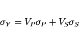 |
(34) |
The solid solution strengthening term discussed above includes the effect of nitrogen concentration. In the calculations that follow, the nitrogen concentration is in the absence of experimental data calculated using methods developed recently (Svensson et al., 1988b; Bhadeshia et al., 1988). It is recognised that these methods are crude, especially for manual metal arc welds, where factors such as arc length and iron powder content have not yet been taken into account. Furthermore, the effects of dilution are not accounted for, although for all-weld metal deposits of the kind considered here, this should not be an important factor. In spite of these difficulties, it is certainly possible to obtain a rough estimate of the nitrogen concentration (Bhadeshia et al., 1988) of MMA weld deposits, as a function of weld chemistry and heat input.
There is a major difficulty in formulating general models for the strength of multirun weld deposits, stemming from the inability to take secondary hardening effects (due to elements like Mo, Cr)
into account in estimating ![]() . While in ordinary welds, the secondary microstructure loses most of its
microstructural strength, that is clearly not the case for secondary hardening alloys, and this leads to an underestimation of strength (Fig. 31). It is
important to realise that precipitation of alloys carbides is not necessary for secondary hardening effects to manifest themselves in hardness data, since preprecipitation phenomena can cause
significant strengthening in the reheated regions. There is as yet, no systematic methodology for taking such effects into account.
. While in ordinary welds, the secondary microstructure loses most of its
microstructural strength, that is clearly not the case for secondary hardening alloys, and this leads to an underestimation of strength (Fig. 31). It is
important to realise that precipitation of alloys carbides is not necessary for secondary hardening effects to manifest themselves in hardness data, since preprecipitation phenomena can cause
significant strengthening in the reheated regions. There is as yet, no systematic methodology for taking such effects into account.
![\includegraphics[width=12cm]{molybdenum.eps}](img233.png) |
There has been a limited amount of progress in the modelling of tensile ductility of the as-deposited microstructure of steel welds (Sugden and Bhadeshia, 1989a). The ductility can to a good approximation be divided into two main components whose magnitudes are assumed to be controlled by different physical processes. These components are the uniform plastic strain, as recorded prior to the onset of macroscopic necking in the tensile specimen, and the nonuniform component which is the remainder of the plastic strain.
By factorising the ductility into these components, it is possible to express the nonuniform component in terms of the inclusion content of the weld deposit, after taking into account variations
in specimen cross-sectional area (![]() ) and gauge length (
) and gauge length (![]() ):
):
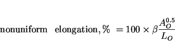 |
(35) |
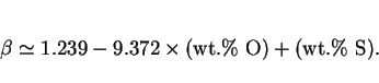
|
(36) |
An acicular ferrite microstructure is usually assumed to be good for the achievement of a high cleavage toughness. This is because the plates of ferrite point in many different directions, and
hence are able to frequently deflect cracks. This should give better toughness when compared with allotriomorphic ferrite, or even Widmanstätten ferrite or bainite, which tends to form in
packets of parallel plates (across which cracks can propagate with relative ease). However, good evidence to this latter effect has been lacking. An example is illustrated in Fig. ![]() , where the fracture assessed impact transition temperature is plotted as a function of
the strength and microstructure (Horii and Okita, 1992). It is obvious that the progressive replacement of a coarse allotriomorphic ferrite microstructure with acicular ferrite, even though the
strength increases in the process.
, where the fracture assessed impact transition temperature is plotted as a function of
the strength and microstructure (Horii and Okita, 1992). It is obvious that the progressive replacement of a coarse allotriomorphic ferrite microstructure with acicular ferrite, even though the
strength increases in the process.
As acicular ferrite is then replaced with bainite, the toughness deteriorates, but the cause of this is not straightforward to interpret because the strength increases at the same time (Fig. 32).
![\includegraphics[width=12cm]{Horii.eps}](img239.png) |
Knott and co-workers have suggested that once a crack is initiated at an inclusion, it propagates without hinderance by acicular ferrite. Recent work by Ishikawa and Haze (1994) has demonstrated that whilst this must be true when the general level of toughness is small, the gradient of stress at any poisition in the vicinity of a crack decreases as the toughness increases. Hence, the propagation behaviour changes, and cleavage cracks are then arrested in an acicular ferrite microstructure but not in one which is dominated by Widmanstätten ferrite.
Fracture mechanics are widely applied in the design of engineering structures, but difficulties arise when repeated tests of the kind used in characterising toughness, on the same material, yield significantly different results. Such scatter in toughness is a common feature of relatively brittle materials such as ceramics, where it is a key factor limiting their wider application even when the average toughness may be acceptable. Steel users have become increasingly aware in recent years that scatter in toughness data can also be of concern in wrought and welded steels. Apart from the difficulties in adopting values for design purposes, the tests necessary for the characterisation of toughness as a material property are rather expensive, the number of experiments needed to establish confidence being larger for less unreliable materials.
A major factor responsible for variations in toughness in welds is likely to be the inclusion population which consists mainly of large oxides originating from the slags used to control the weld pool stability and composition. The inclusions are neither uniform in size, nor are they uniformly distributed in the weld. There is also mounting evidence that variations in microstructure can also be an important factor in influencing scatter in toughness data (Tweed & Knott, 1983, 1987; Bowen et al., 1986; Neville and Knott, 1986; Hagiwara and Knott, 1980). Neville (1985) noted that microstructural inhomogeneities such as hard pearlite islands, can lead to a significant variations in measured fracture toughness values during repeat tests on specimens of the same material.
The two quantities that need to be defined in order to assess variations in mechanical properties are the degree of scatter, and the heterogeneity of microstructure. The definitions have to be of a kind amenable to alloy design techniques, while at the same time being physically meaningful.
Consider the scatter commonly observed in impact toughness data. The three most frequently used ways of rationalising variations in results from the toughness testing of weld metals are to take an average of the Charpy readings obtained at a given temperature, measure the standard deviation (Drury, 1984), or plot the lowest Charpy readings obtained in order to focus attention on the lower ends of the scatter bands (Taylor, 1982).
An alternative to this was suggested by (Smith, 1983) who proposed a scatter factor ![]() to quantify any spread
obtained in Charpy values, where
to quantify any spread
obtained in Charpy values, where
 |
(37) |
None of the methods discussed above are completely suitable for alloy design purposes, where the aim is to minimise scatter over the whole of the impact transition curve (the plot of impact energy versus test temperature). An idealised impact energy-temperature curve should be sigmoidal in shape, and the scatter of experimental data can in principle be measured as a root-mean-square deviation about a such a curve, obtained by best-fitting to the experimental data. This gives a representation of scatter in which one value of scatter is defined for each complete impact transition curve. It has the advantage that the value represents the entire dataset used in generating the transition curve.
Since it is believed that the scatter in Charpy data is amongst other factors, dependent on the nonuniformity of weld microstructure, the degree of inhomogeneity needs to be quantified. This can
be done by calculating the entropy ![]() of a given microstructure (Lange, 1967; Karlin and Taylor, 1975).
of a given microstructure (Lange, 1967; Karlin and Taylor, 1975).
If ![]() is a random variable assuming the value
is a random variable assuming the value ![]() with probability
with probability ![]() ,
, ![]() , the entropy of
, the entropy of ![]() , as a logarithmic measure of the mean probability, is computed according to
, as a logarithmic measure of the mean probability, is computed according to
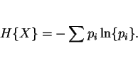 |
(38) |
The primary microstructure of most common welds can be taken as having three principal constituents: acicular, allotriomorphic and Widmanstätten ferrite. It is important to emphasise that
although ![]() and
and ![]() have
similar strengths, the weld metal microstructure cannot be treated as a two-phase microstructure (with
have
similar strengths, the weld metal microstructure cannot be treated as a two-phase microstructure (with ![]() and
and
![]() grouped together), since the toughnesses of the two phases are quite different. Therefore, the entropy
of a given weld metal microstructure
grouped together), since the toughnesses of the two phases are quite different. Therefore, the entropy
of a given weld metal microstructure
![\begin{displaymath}H = - [V_\alpha \ln \{V_\alpha\} + V_a \ln \{V_a\} + V_w \ln \{V_w\}] \end{displaymath}](img251.png)
|
(39) |
The entropy of the distribution quantifies the heterogeneity of the microstructure. ![]() will vary from zero for an
homogeneous material to
will vary from zero for an
homogeneous material to ![]() (i.e. 1.099) for a weld with equal volume fractions of the three phases. By
multiplying by
(i.e. 1.099) for a weld with equal volume fractions of the three phases. By
multiplying by ![]() , the heterogeneity of the three phase microstructure of a weld may be defined on a scale
from zero to unity, i.e.
, the heterogeneity of the three phase microstructure of a weld may be defined on a scale
from zero to unity, i.e.
 |
(40) |
![\begin{displaymath}Het_2 = - [V_p\ln \{V_p\} + V_s\ln \{V_s\}] \times {{1} \over {\ln \{2\}}} \end{displaymath}](img258.png) |
(41) |
It is evident from (Fig. 34a) that there is a strong relationship between the scale parameter, and microstructural heterogeneity for low-alloy steel all-weld metals. Consequently, a significant part of the observed scatter in weld metal Charpy results is attributable to the inhomogeneity of the microstructure, with larger scatter being associated empirically with more heterogeneous microstructures. This result can be compared with the common feature of fracture toughness experiments where the positioning of the fatigue crack is found to be an important factor in CTOD testing of weldments.
The relatively poor correlation for the multipass welds (Fig. 34b) highlights a limitation of this technique. The failure of the method for multirun welds might be attributed to the small range of microstructural entropy in the data analysed, so that the major differences in scatter are attributable to factors such as inclusions rather than microstructure. Secondly, the microstructural entropy term does not weight the phases involved in terms of their mechanical properties, but rather in terms of their volume fractions. This is a significant weakness of the method, since it would predict heterogeneity in a multiphase system even when all the phases exhibit identical mechanical properties. For multirun welds, it is known that the strength of the reheated regions scales with that of the as-deposited regions, so that differences in mechanical properties in such welds should be less than expected intuitively.
![\includegraphics[width=12cm]{Figa26.eps}](img261.png) |
Copper has two primary effects, firstly to retard the transformation of austenite (since it is an austenite stabilising element), and secondly to strengthen ferrite via the precipitation of ![]() -Cu. **Comment somewhere on the role of nickel in copper bearing steels.
-Cu. **Comment somewhere on the role of nickel in copper bearing steels.
In manual metal arc welds, copper is not surprisingly found to lead to an increase in strength, but at concentrations in excess of about 0.7 wt.% to a deterioration in toughness in both the as-welded and stress-relieved states (Es-Souni et al., 1990). There may be a simple explanation for this, in that an increase in strength should indeed lead to a deterioration of toughness, since the comparisons are never at constant strength.
Kluken et al. (1994) showed that in submerged arc welds, the yield strength is less sensitive to copper additions than the ultimate tensile strength, perhaps because the copper precipitates cause a greater rate of work hardening. On the other hand, Es-Souni et al. (1990) found the rate of change, as a function of the copper concentration, to be identical for both the yeild and tensile strengths, in manual metal arc welds.
The austenite stabilising effect of copper seems to cause either an increase in the microphase content, or changes the nature of the microphases from cementite and ferrite to mixtures of retained austenite and high-carbon martensite (Es-Souni et al., 1990; Alekssev et al., 1991). The presence of copper has not been found to influence either the distribution or the nature of the usual non-metallic inclusions found in steel weld deposits (Es-Souni et al., 1990).
The research reviewed above is limited in some important aspects. The amount of work that needs to be done in order to produce a reliable description of a complete welded joint is daunting. It is hoped that the ideas formulated below stimulate specific investigations in the field of microstructure modelling of welds. A possible form of a coordinated programme of research is illustrated in Fig. 34. It consists of the following major elements, discussed in detail in the sections that follow:
Kinetics of the Acicular Ferrite Reaction: Acicular ferrite is beneficial in welds because of its ability to deflect cleavage cracks. There is growing evidence that the mechanism of transformation of acicular ferrite is similar to that of bainite. The microstructures look different because acicular ferrite nucleates intragranularly from point sites (inclusions), and impingement with other plates growing from adjacent sites prevents the development of the sheaf morphology associated with bainite. Acicular ferrite plates radiate in many different directions from their point nucleation sites, frequently deflecting any advancing crack.
Current weld models deal with the acicular ferrite content by difference, and consequently fail when it is the first phase to form during the cooling of austenite, as happens in many high-strength
welds. There is therefore, a pressing need for a first principles theoretical treatment of the kinetics of the acicular ferrite reaction. This has never before been attempted, probably because the
transformation mechanism has only recently been clarified. Kinetic theory has been developed for bainitic transformations (Bhadeshia, 1981a). This theory accounts for the fact that the activation
energy ![]() for nucleation varies linearly with the chemical driving force (i.e.,
for nucleation varies linearly with the chemical driving force (i.e., ![]() ) rather than the inverse square relationship found in conventional theory
(i.e.,
) rather than the inverse square relationship found in conventional theory
(i.e., ![]() ). This peculiar dependence is a consequence of the displacive
nucleation mechanism. The kinetic theory also includes the condition that bainitic growth ceases in circumstances far from equilibrium, when diffusionless transformation becomes thermodynamically
impossible, so that the reaction ceases when the residual austenite reaches a composition given by the
). This peculiar dependence is a consequence of the displacive
nucleation mechanism. The kinetic theory also includes the condition that bainitic growth ceases in circumstances far from equilibrium, when diffusionless transformation becomes thermodynamically
impossible, so that the reaction ceases when the residual austenite reaches a composition given by the ![]() curve on
the phase diagram. This particular characteristic has been demonstrated also for acicular ferrite.
curve on
the phase diagram. This particular characteristic has been demonstrated also for acicular ferrite.
Given the analogy between bainite and acicular ferrite, it should be possible to formulate the kinetic theory for acicular ferrite after accounting for its intragranular nucleation. Experiments are needed to verify the dependence of the activation energy for the nucleation of acicular ferrite on inclusions, on the chemical driving force. In particular, it is necessary to design and study samples in which the ratio of grain surface to intragranular nucleation densities varies. Monitoring the onset of a detectable degree of acicular ferrite formation then enables the free energy dependence to be deduced. It should be necessary to cover a range of alloys to give sufficient variation in the driving force at constant temperature. The theory should then be tested against experimental kinetic data on acicular ferrite in low-alloy steels.
Nucleation-Diffusion Bonding Experiments: The complex microstructure and constitution of the nonmetallic inclusions responsible for acicular ferrite nucleation makes it difficult to conduct controlled experiments to assess their nucleation potencies. Some feasibility studies have been conducted using a new technique designed to overcome these problems (Strangwood, 1987). Pure ceramics of well defined composition, purity, crystallinity and structure were diffusion bonded to steels which were then heat treated. By comparing the events at the ceramic/steel interface with those within the steel at a distance from this interface, it is possible to deduce conclusively whether the ceramic stimulates ferrite nucleation. These experiments were limited by the equipment then available. Modern thermomechanical simulators should enable the study of the heterogeneous nucleation of acicular ferrite on ceramics rather than the allotriomorphic ferrite obtained in earlier experiments (Strangwood & Bhadeshia, 1988).
Inclusion Microstructure: It is currently assumed in calculations that the weld deposit contains sufficient intragranular nucleation sites for acicular ferrite formation. This has been shown to be reasonable for typical arc welds which contain sufficient levels of impurity elements, and for those welds in which the acicular ferrite content depends largely on the major alloying additions. There is nevertheless, a considerable body of evidence that in certain welds, quantities of boron, titanium, aluminium, sulphur, nitrogen, and other trace elements can alter the evolution of the microstructure. To deal with these important cases, it is necessary to be able to predict and control the inclusion microstructure and chemistry.
The modelling of inclusions from a knowledge of the trace elements has relied on the assumption of chemical equilibrium and a phenomenological sequence of reactions, carried out in an order consistent with the perceived thermodynamic stability of the individual elements. This leads to anomalies, such as the incorrect prediction of TiN/TiO precipitation. There is also the doubtful assumption that the relative stabilities of the compounds that form can be assessed using free energy data which are standardised for the reaction of each metallic element with one mole of oxygen, the oxide and the pure element have unit activities. In fact, all the reactant and product activities are far from unity, so that the ranking of the oxide stabilities can change significantly as a function of the actual concentrations involved. It is necessary to investigate a more rigorous method based on solution thermodynamics and growth kinetics. The activities of the individual trace elements will be computed using Wagner interaction parameters (some of which will have to be deduced from an assessment of the appropriate phase diagrams and thermochemical data), so that the oxidising or nitriding potentials, and the reaction states, of the individual elements can be ranked correctly.
Past efforts at the prediction of the microstructure in the heat affected zones of steel welds, consist essentially of heat flow and austenite grain growth theory, combined with highly empirical microstructural estimates. There remain major hurdles in the modelling of multirun welds and their heat-affected zones. Such welds are fabricated by sequentially depositing many layers of metal in order to fill the weld gap; this procedure is adopted where quality is of paramount importance. The completed layers are therefore reheated each time a new layer is deposited. This causes them to undergo partial or complete reverse transformation to austenite which on subsequent cooling retransforms to a different secondary microstructure. Other regions of this secondary microstructure which do not reach high enough peak temperatures are tempered during reheating.
The theory for the rate of the reverse transformation to austenite, and hence for predicting the secondary microstructure hardly exists in any useful form, making it impossible to predict a TTT diagram for reaustenitisation, let alone partial reaustenitisation. The subsequent decomposition of the austenite cannot be modelled with any confidence; nor can the changes in the tempered regions. The ideas for developing such theory are discussed below.
Conditions at the transformation interface: Austenite in welds grows by reconstructive transformation because the high temperatures involved permit a closer approach to equilibrium. Unlike
the ![]() reaction, both the driving force for transformation and the diffusivity increase with
superheat, so that the reaction rate increases indefinitely with temperature. The mechanism of reconstructive transformation is complicated by the multicomponent constitution of most steels. Several
species of atoms therefore diffuse during growth, at very different rates, and it is not a trivial matter to match the fluxes of all the elements in a manner consistent with the velocity of the
interface, while at the same time, retain local equilibrium exists at the interface. When Fe-C-X alloys (X being a metallic solute) are transformed at low supersaturations, there is bulk partitioning
of the slow diffuser, the activity gradient of the fast diffuser being reduced to a negligible level. At larger supersaturations, there is negligible partitioning of the slow diffuser, so that its
activity gradient in the parent phase is large enough to allow it to keep pace with the faster diffusing element. Paraequilibrium transformation involves zero partitioning of substitutional elements
during transformation, the ratio of substitutional solute to iron atoms being constant everywhere, even on the finest conceivable scale.
reaction, both the driving force for transformation and the diffusivity increase with
superheat, so that the reaction rate increases indefinitely with temperature. The mechanism of reconstructive transformation is complicated by the multicomponent constitution of most steels. Several
species of atoms therefore diffuse during growth, at very different rates, and it is not a trivial matter to match the fluxes of all the elements in a manner consistent with the velocity of the
interface, while at the same time, retain local equilibrium exists at the interface. When Fe-C-X alloys (X being a metallic solute) are transformed at low supersaturations, there is bulk partitioning
of the slow diffuser, the activity gradient of the fast diffuser being reduced to a negligible level. At larger supersaturations, there is negligible partitioning of the slow diffuser, so that its
activity gradient in the parent phase is large enough to allow it to keep pace with the faster diffusing element. Paraequilibrium transformation involves zero partitioning of substitutional elements
during transformation, the ratio of substitutional solute to iron atoms being constant everywhere, even on the finest conceivable scale.
There is no satisfactory theory for the transition from local equilibrium to paraequilibrium. The conjecture that the transition occurs when the calculated extent of the diffusion field of the slow diffuser becomes comparable to atomic dimensions is known to be incorrect. For austenite growth, the task is rather more complicated in that the transition from local to paraequilibrium is expected to occur as the transformation temperature increases. The transition is therefore not stimulated by a lack of atomic mobility, but by an increase in the interface velocity.
Concentration profiles at the transformation interfaces have to be characterised in detail, firstly to establish the local equilibrium assumption, and secondly to provide direct experimental data on the conditions under which local equilibrium gives way to paraequilibrium during reaustenitisation. It may even be the case that the paraequilibrium condition does not exist when the mechanism of transformation is reconstructive. These characterisations require chemical and spatial resolution on an atomic scale for all the relevant elements and will be carried out using a specially designed field-ion microscope/atom probe.
Solute Trapping Although it is usual to assume the existence of some kind of equilibrium or constrained equilibrium at the transformation interface, there is in principle not reason why the transformation should not occur with some partitioning of solute species, and some solute trapping. Trapping implies that the chemical potential of the species increases on transfer across the interface, and represents a nonequilibrium event. There could thus be an infinite number of possible kinetic conditions between the states of local equilibrium and paraequilibrium.
It is possible to obtain unique solutions for the relation between interface velocity, transformation temperature and carbon supersaturation by solving simultaneously, three separate interface response functions which are descriptions of interface mobility, diffusion field velocity and solute trapping velocity. We propose to develop this theory for reaustenitisation. A major advantage here is that the partially transformed sample can be configurationally frozen by quenching for subsequent examination in an atom-probe. The research should help resolve many fundamental issues on nonequilibrium transformations.
Overall Kinetics of Reaustenitisation: Quantitative studies of the degree of isothermal austenite formation as a function of time, temperature and alloy chemistry will form an essential database for the kinetic theory. Initial experiments will be conducted on samples already containing some austenite so that the growth phenomenon can be studied in isolation. Further work will compare against the growth experiments to reveal clearly the role of austenite nucleation. TTT and continuous-heating-transformation diagrams for reaustenitisation as a function of different starting microstructures will be measured for the analysis discussed below. In this context, it is noteworthy that attempts at predicting the austenite grain size are based entirely on coarsening theory. This ignores the fact that the grain size prior to the onset of coarsening is determined by the austenite to ferrite transformation kinetics. The work proposed here is an ideal basis for a fresh look at austenite grain size prediction, including the alloy carbide/nitride solution and precipitation kinetics.
Kinetic Model for Reaustenitisation: The aim here would be to produce a model capable of calculating the TTT diagrams for reaustenitisation as a function of alloy chemistry and starting microstructure. This is probably a very ambitious aim - it has never before been attempted, and the number of variables is very large indeed. For this reason, initial work should focus on starting microstructures important in the welding problems, consisting mainly of allotriomorphic ferrite, Widmanstätten ferrite and acicular ferrite. Overall reaction kinetics will be treated in terms of the theory of nucleation and growth in multicomponent systems. The diffusion during growth (unusually) takes place in the growing phase (austenite). Since the austenite particles are at first very small, soft-impingement (overlap of diffusion fields) effects occur early in the transformation. Consequently, finite difference methods will have to be used in the prediction of kinetic behaviour and in the treatment of the transformation behaviour of partially reaustenitised microstructures.
None of the weld microstructure models to date take any account of the influence of stress on transformation kinetics, even though the residual stresses in constrained welds can be limited only by yielding. Displacive transformations such as acicular ferrite should be particularly sensitive to stress since the invariant-plane strain (IPS) shape deformation has a large shear component. Its interaction with the applied stress (or that of the lattice deformation during nucleation) adds a `` mechanical" driving force, which may complement or oppose the chemical driving force. For acicular ferrite, the stored energy due to the IPS shape deformation is a large fraction of the typically available chemical driving force.
Any response to stress for transformations like acicular ferrite, is complicated by the partitioning of carbon either after or during growth. There is no quantitative treatment in this respect, probably because the reported experiments are incomplete from the point of view of theoretical analysis. The transformation strains have been never been monitored along more than one direction; in fact, they are not expected to be isotropic, given the IPS shape change and the inevitable fact that polycrystalline specimens are textured. Consequently, uniaxial data are of little use in deconvoluting the total strain into transformation plasticity and dilatational strain.
It is necessary to study of both the bainite and acicular ferrite reactions with the samples under tensile or compressive stresses. The bainite to acicular ferrite transition will be induced by altering the relative number densities of austenite grain to intragranular nucleation sites. Stress well below the austenite yield strength will be applied at first, during isothermal transformation, to avoid complications due to plastic deformation prior to transformation. The kinetics of the transformation and the transformation plasticity must be deduced as a function of time at temperature using radially symmetrical samples.
The absolute dilatational strains can be converted directly to the extent of reaction. For the growth process, it is likely that the stress effect can be modelled from the interaction of the
macroscopic shape strain with the applied stress. Additional factors that may have to be considered include any changes in the level of intervariant-accommodation as the microstructure complies with
the imposed stress, and any consequent changes in the degree of plastic accommodation of the shape strain. Differential scanning calorimetry experiments can be conducted to measure the amount of
energy stored in the sample after ordinary transformation, and that after transformation under stress. The nucleation-stress interaction is more complicated by virtue of the fact that it is less
understood. The nucleation behaviour of bainite (and perhaps that of acicular ferrite) can be rationalised using martensitic nucleation theory but allowing the partitioning of carbon at the
nucleation stage. The free energy needed to obtain a detectable rate of nucleation has to exceed a level specified by the universal function ![]() (a unique function for all steels) which varies linearly with temperature. Experiments will be conducted on acicular ferrite to verify this behaviour in zero stress
experiments, followed by the application of finite stresses.
(a unique function for all steels) which varies linearly with temperature. Experiments will be conducted on acicular ferrite to verify this behaviour in zero stress
experiments, followed by the application of finite stresses.
The nucleation and growth phenomena can then be combined into an overall transformation kinetics model to cover anisothermal transformation kinetics, beginning with the pragmatic approximation of additivity.
The measured strains can form the basis of a model for calculating the residual stress developed in welds as they cool. Some classic experiments by Jones and Alberry illustrated clearly that displacive reactions alter radically the nature of the residual stresses. However, the usual assumption that the effect arises due to transformation plasticity caused by volume changes is bound to be incorrect, because the stress favours compliant crystallographic variants so that the transformation plasticity may be dominated by the much larger shear strains.
Some samples will be metallographically polished prior to transformation under stress in the environmental chamber of the thermomechanical simulator, giving unique data on the stress / crystallography interaction, data of importance in choosing variant selection criteria, and hence in calculating the mechanical driving force. Experimental data will be collected for a number of designed alloys, including those giving carbide-free transformations, and others in which mixed allotriomorphic/bainite microstructures are obtained. In this way, the effects of mixed reactions (which inevitably happen in ``real" situations can also be characterised.
Mechanically Homogeneous, High-Strength Multirun Welds: There is growing evidence that mechanical and microstructural inhomogeneity of the type associated with multirun welds leads scatter in mechanical properties. For toughness, the lower bound within the scatter has to be accepted for design, leading to a less than optimum exploitation of material properties. The problem can be circumvented in single-run welds but the high heat input required leads to poorer quality. Tempering treatments or weld refinement techniques can also lead to mechanical homogeneity but at the expense of mean strength. Here we suggest a novel method designed to produce homogeneous multirun welds of high strength and toughness, with a microstructure of acicular ferrite and ductile martensite by simultaneously satisfying four conditions:
There are many investigations which suggest that Widmanstätten ferrite can be detrimental to toughness (Owen et al., 1957; Gulyaev and Guzovskaya, 1977; Koval'chuk et al., 1979; Chilton and Roberts, 1979, 1980; Otterberg et al., 1980; Stenbacka, 1980; Morrison and Preston, 1984; Glover et al., 1984; Huang et al., 1989). Recent work involving controlled experiments has, however, established that when the microstructure is changed from one which is predominantly allotriomorphic ferrite, to one containing Widmanstätten ferrite, there is an improvement in both the toughness and strength (Bodnar and Hansen, 1994). This might be expected since large fractions of Widmanstätten ferrite are usually associated with refined microstructures.
It is sometimes claimed that the presence of Widmanstätten ferrite changes the deformation behaviour by inducing continuous yielding during tensile deformation, whereas discontinuous yielding is characteristic of microstructures dominated by allotriomorphic ferrite. However, some careful studies by Bodnar and Hansen (1994) show that even microstructures containing Widmanstätten ferrite often show discontinuous yielding behaviour. They suggested that in cases where continuous yielding has been reported, the microstructures contained sufficient quantities of bainite or martensite to mask the deformation behaviour of Widmanstätten ferrite.
Table 4 lists the key characteristics of phase transformations in steels. The nomenclature used for the transformation products is as follows: martensite (![]() ), lower bainite (
), lower bainite (![]() ), upper bainite (
), upper bainite (![]() ), acicular ferrite (
), acicular ferrite (![]() ),
Widmanstätten ferrite (
),
Widmanstätten ferrite (![]() ), allotriomorphic ferrite (
), allotriomorphic ferrite (![]() ), idiomorphic ferrite (
), idiomorphic ferrite (![]() ), pearlite (
), pearlite (![]() ), substitutional alloying elements (
), substitutional alloying elements (![]() ). Consistency of a
comment with the transformation concerned is indicated by (=), inconsistency by (
). Consistency of a
comment with the transformation concerned is indicated by (=), inconsistency by (![]() ); cases where the comment is
only sometimes consistent with the transformation are indicated by a bullet (
); cases where the comment is
only sometimes consistent with the transformation are indicated by a bullet (![]() ). The term parent
). The term parent ![]() implies the
implies the ![]() grain in which the
product phase grows. Note that it is not justified to distinguish massive ferrite from
grain in which the
product phase grows. Note that it is not justified to distinguish massive ferrite from ![]() .
.
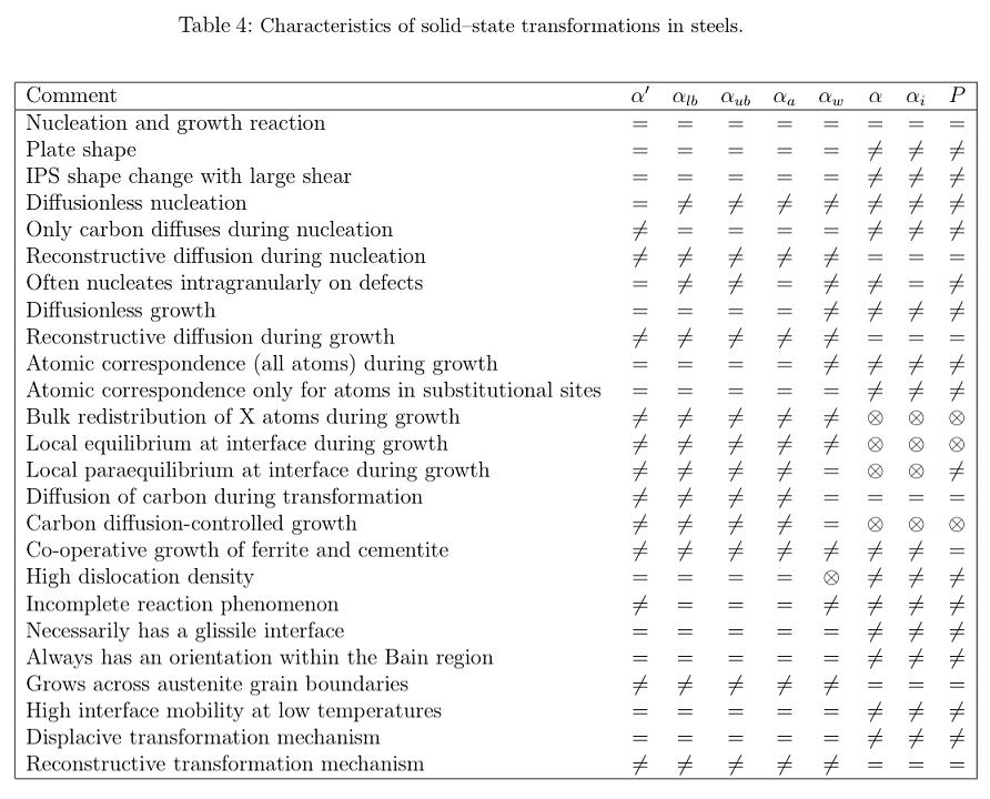
Nucleation and growth reactions are of first order in the Ehrenfest classification; in all such reactions, the parent and product phases can coexist, and are separated by well-defined interfaces. Martensitic transformations, although they can be rapid, still involve a nucleation and growth process.
It is significant that all of the ferrite crystals which grow in the form of plates cause an invariant-plane shape deformation which is dominated by shear. The ferrite within pearlite does not have a plate morphology; Hillert showed some time ago that it is wrong to consider pearlite as alternating layers of ferrite and cementite - instead a colony of pearlite is an interpenetrating bicrystal of ferrite and cementite.
Reconstructive diffusion is the flow of matter necessary to avoid the strains characteristic of displacive transformations. A diffusional transformation may phenomenologically be regarded as a combination of a lattice change and a recrystallisation of the product phase, reconstructive diffusion being the flow necessary for the recrystallisation process.
In diffusionless transformations, it is possible to specify (in a localised region at least) how particular vectors, planes and unit cells of one structure (defined by an imaginary labelling of the individual atoms) are derived from corresponding vectors, planes and unit cells of the other structure. This is termed a lattice correspondence and it defines a pure lattice deformation which carries the original lattice points, or some fraction of these points into points of the new lattice. When interstitial atoms are present, they may move over large distances during transformation without affecting the lattice correspondence; this is sometimes loosely expressed by stating that there is an atomic correspondence for the solvent and substitutional solute atoms but not for the interstitial atoms. A further relaxation of the condition is to allow the solvent and substitutional solute atoms to be displaced during transformation among the sites specified by the lattice correspondence, but not to create new sites or to destroy any specified sites; in this way the lattice correspondence is preserved but there is no longer an atomic correspondence. Note that in the classification presented above, the single atomic jumps of interstitial atoms needed to destroy Zener ordering (which is produced automatically by the Bain correspondence) are not taken into account.
Even though two crystals may have an identical bulk composition, it may not be concluded that their compositions at the transformation interface are identical. There are modes of transformation (e.g., negligible partitioning local equilibrium) where the bulk compositions are predicted to be identical but where the phases differ in the vicinity of the transformation interface. For plain carbon steels, there is no difference between equilibrium and paraequilibrium.
The incomplete reaction phenomenon implies that when a reaction can be studied in isolation, it stops before the phases reach their equilibrium or paraequilibrium compositions when stored energy terms have been accounted for.
An orientation within the Bain region means a reproducible relation which may be irrational but is close to the rational NW or KS relations.
Massive ferrite is not classified as a separate morphology since it can be included within allotriomorphic or idiomorphic ferrite.
We are grateful to ESAB AB (Sweden) for financing some of this research, and to Professor Colin Humphreys for the provision of research facilities at the University of Cambridge. The Science and Engineering Research Council also provided financial support via several CASE awards. It is a particular pleasure to acknowledge the numerous contributions made by members of the Phase Transformations Group at Cambridge. Our discussions with Suresh Babu have been particularly stimulating. Some of this work has been carried out under the auspices of the ``Atomic Arrangements: Design and Control Project", which is a collaboration between the University of Cambridge and the Japan Research and Development Corporation.
Abson, D. J., (1987a) Nonmetallic Inclusions in Ferritic Steel Weld Metals - A Review, IIW Doc. IX-1486-87. truemm
Abson, D. J., (1987b) Welding Institute Research Report 7931.01/86/544.3. The Welding Institute, Cambridge, U. K., 1-30.truemm
Abson, D. J., (1988) Welding Institute Research Report 376/1988, Cambridge, UK. truemm
Abson, D. J. and Pargeter, R. J., (1986) Int. Met. Rev., 31, 141-194.truemm
Akselsen, O. M., Grong, ![]() ., Ryum, N. and Christensen, N., (1986) Acta Metallurgica, 34,
1807-1815.truemm
., Ryum, N. and Christensen, N., (1986) Acta Metallurgica, 34,
1807-1815.truemm
Alberry, P. J. and Jones, W. K. C., (1979) CEGB report R/M/R282, Marchwood Engineering Laboratories, Marchwood, Southampton, U. K. truemm
Alberry, P. J. and Jones, W. K. C., (1982) Metals Technology, 9, 419-427.truemm
Alberry, P. J., Brunnstrom, R. R. L. and Jones, K. E., (1983) Metals Technology, 10, 28-38.truemm
Alekseev, A. A., Shevchenko, G. A., Pokhodnya, I. K. and Yurlov, B. V., (1991) Effect of copper on structure and properties of multilayer C-Mn-Ni weld metal IIW Document II-A-845-91, 1-7.truemm
Ashby, M. F. and Easterling, K. E., (1982) Acta Metallugica, 30, 1969-1978.truemm
Atkinson, C., (1967) Numerical Solutions to Planar Growth where the Diffusion Coefficient is Concentration Dependent, Acta Metallurgica, 16, 1019-1022.truemm
Babu, S. S. and Bhadeshia, H. K. D. H., (1990) Materials Science and Technology, 6, 1005-1020.truemm
Babu, S. S., Bhadeshia, H. K. D. H. and Svensson, L.-E., (1991) J. of Materials Science Letters, 10, 142-144.truemm
Babu, S. S. and Bhadeshia, H. K. D. H., (1992) Materials Science and Engineering, A156, 1-9.truemm
Bailey, E. F., (1954) Transactions ASM, 46, 830-850.truemm
Baker, R. G. and J. Nutting, (1959) Journal of the Iron and Steel Institute, 192, 257-268.truemm
Barbaro, F. J., Edwards, R. H. and Easterling, K. E., (1988) The Composition and Morphology of Nonmetallic Inclusions in HSLA Steel Weld Metals, Proc. 7th Australian X-Ray Analysis Association AXAA-88, University of Western Australia, 1-14.truemm
Barbaro, F. J., Krauklis, P. and Easterling, K. E., (1989) Materials Science and Technology, 5, 1057-1068.truemm
Barritte, G. S. and Edmonds, D. V., (1982) Advance in the Physical Metallurgy and Applications of Steels, The Metals Society, London, 126-135.truemm Barritte, G. S., Ricks, R. A. and Howell, P. R., (1982) Quantitative Microanalysis with High Spatial Resolution, The Metals Society, London. 112-118.truemm
Bhadeshia, H. K. D. H., (1981a) Acta Metallurgica, 29, 1117-1130.truemm
Bhadeshia, H. K. D. H., (1981b) Metal Science, 15, 477-479.truemm
Bhadeshia, H. K. D. H., (1982) Metal Science, 16, 159-165.truemm
Bhadeshia, H. K. D. H., (1985a) Progress in Materials Science, 29, 321-386.truemm
Bhadeshia, H. K. D. H., (1985b) Mat. Science and Technology, 1, 497-504.truemm
Bhadeshia, H. K. D. H., (1987) Geometry of Crystals, Institute of Metals, London, p.55.truemm
Bhadeshia, H. K. D. H., (1988a) Scripta Metallurgica, 22, I-IV.truemm
Bhadeshia, H. K. D. H., (1988b) Phase Transformations '87, Ed. G. W. Lorimer, Institute of Metals, London, 309-314.truemm
Bhadeshia, H. K. D. H., (1989) Recent Trends in Welding Science and Technology, eds. S. A. David and J. M. Vitek, ASM International, Ohio, U. S. A., 189-198.truemm
Bhadeshia, H. K. D. H., (1990) Metallurgy, Welding and Qualification of Microalloyed (HSLA) Steel Weldments, American Welding Society, Florida, U.S.A., 1-35, in press.truemm
Bhadeshia, H. K. D. H. and D. V. Edmonds, (1980) Acta Metallurgica, 28, 1265-1273.truemm
Bhadeshia, H. K. D. H., Svensson, L.-E. and Gretoft, B., (1983) Acta Universitatis Ouluensis, Series C, No.26, University of Oulu, Finland (Proc. of the 3rd Scandanavian Symposium on Materials Science), 73-78.truemm
Bhadeshia, H. K. D. H., Svensson, L.-E. and Gretoft, B., (1985a) Acta Metallurgica, 33, 1271-1283.truemm
Bhadeshia, H. K. D. H., Svensson, L.-E. and Gretoft, B., (1985b) J. of Materials Science Letters, 4, 305-308.truemm
Bhadeshia, H. K. D. H., Svensson, L.-E. and Gretoft, B., (1986a) J. Mat. Science, 21, 3947-3951.truemm
Bhadeshia, H. K. D. H., Svensson, L.-E. and Gretoft, B., (1986b) 4th Scand. Symp. on Mat. Science, Norwegian Institute of Technology, Norway, 153-158.truemm
Bhadeshia, H. K. D. H., Svensson, L.-E. and Gretoft, B., (1986c) Prediction of the Microstructure of Submerged-Arc Linepipe Welds, Proceedings of the Third International Conference on Welding and Performance of Pipelines, ed. P. M. Hart, Welding Institute, Cambridge, 1-10.truemm
Bhadeshia, H. K. D. H., Svensson, L.-E. and Gretoft, B., (1987a) Welding Metallurgy of Structural Steels, ed. J. Y. Koo, AIME, Warrendale, Penn. 517-530.truemm
Bhadeshia, H. K. D. H., Svensson, L.-E. and Gretoft, B., (1987b) Advances in the Science and Technology of Welding, ASM, Metals Park, Ohio, 225-229.truemm
Bhadeshia, H. K. D. H., Svensson, L.-E. and Gretoft, B., (1988) J. Materials Science Lett., 7, 610-612.truemm
Bhadeshia, H. K. D. H. and Svensson, L.-E, (1989a) Effect of Alloying Additions on the Microstructure and Properties of Vertical-Up MMA Welds, Part I, Joining and Materials, 2, 182R-187R.truemm
Bhadeshia, H. K. D. H. and Svensson, L.-E, (1989b) Effect of Alloying Additions on the Microstructure and Properties of Vertical-Up MMA Welds, Part II, Joining and Materials, 2, 236R-238R.truemm
Bhadeshia, H. K. D. H., and Svensson, L.-E., (1989c) J. Materials Science, 24, 3180-3188.truemm
Bhadeshia, H. K. D. H. and Christian, J. W., (1990) Metallurgical Transactions A, 21A, 767-797.truemm
Bodnar, R. L. and Hansen, S. S., (1994) Metallurgical and Materials Transactions A, 25A, 763-773.truemm
Bowen, P., Druce, S. G. and Knott, J. F., (1986) Acta Metallurgica, 34, 1121-1131.truemm
Briant, C. L. and Banerji, S. K., (1978) International Metals Reviews, 232, 164-199.truemm
Bramfitt, B. L. and Marder, A. R., (1973) Metallurgical Transactions, 4, 2291.truemm
Bronshtein, I. N. and Semendyayev, K. A., (1973) A Guide Book to Mathematics, Verlag Harri Deutsch, Frankfurt, Germany, 106-107.truemm
Buchmayr, B. and Cerjak, H., (1988) ``Weld Quality: Role of Computers" Pergamon Press, Oxford, 43-50.truemm
Buki, A. A., (1992) Calculating the chemical composition of deposited metal when welding with coated electrodes Welding International, 6, 818-820.truemm
Calvo, F. A., Bently, K. P. and Baker, R. G., (1963) Studies of the Welding Metallurgy of Steels, BWRA, Abingdon, Cambridge, 71.truemm
Chandrasekharaiah, M. N., Dubben, G. and Kolster, B. H., (1994) An atom probe study of retained austenite in ferritic weld metal American Welding Journal, 71, 247s-252s.truemm
Chart, T. G., Counsell, J. F., Jones, G. P., Slough, W., Spencer, P. J., (1975) Int. Met. Rev., 20, 57-82.truemm
Chen, J. H., Kikuta, Y., Araki, T., Yoneda, M. and Matsuda, Y., (1984) Acta Metallurgica, 32, 1779-1788.truemm
Chijiiwa, R., Tamehiro, H., Hirai, M., Matsuda, H. and Mimura, H., (1988) Offshore Mechanicas and Arctic Engineering Conference, Houston, Texas. truemm
Chilton, J. M. and Roberts, M. J., (1979) Vanadium in High Strength Steels, Vanitec, London, 11-21.truemm
Chilton, J. M. and Roberts, M. J., (1980) Metallurgical Transactions A, 11A, 1711-1721.truemm
Christian, J. W., (1975) Theory of Transformations in Metals and Alloys, 2nd ed., Part I, Pergamon Press, Oxford. truemm
Christian, J. W. and Edmonds, D. V., (1984) Phase Transformations in Ferrous Alloys, Eds. Marder and Goldstein, TMS-AIME, Pennsylvania, USA, 293-326.truemm
Coates, D. E., (1973) Diffusional Growth Limitation and Hardenability, Metallurgical Transactions, 4, 2313-2325.truemm
Court, S. and Pollard, J., (1987) Welding Metallurgy of Structural Steels, ed. J. Y. Koo, TMS-AIME, Pennsylvania, 335-349.truemm
Dadian, M., (1986) Advances in the Science and Technology of Welding, Ed. S. A. David, ASM, Metals Park, OH 44073, 101-117.truemm
Daigne, J., Guttman, M. and Naylor, J. P., (1982) Materials Science and Engng., 56, 1-10.truemm
Dallum, C. B. and Olson, D. L., (1989) Stress and Grain Size Effects on Weld Metal Ferrite Formation, American Welding Journal, 198s-205s.truemm
Dan, T. and Gunji, K., (1984) Transactions Nat. Res. Inst. for Metals (Japan), 26, 8.truemm
Davenport, E. S. and Bain, E. C., (1930) TMS AIME, 90, 117-154.truemm
Davies, G. J. and Garland, J. G., (1975) Int. Metallurgical Rev., 20, 83-106.truemm
Deb, P., Challenger, K. D. and Therrien, A. E., (1987) Structure-property correlation of SA and GMA weldments in HY100 steel, Metallurgical Transactions A, 18A, 987-999.truemm
Dowling, J. H., Corbett, J. H. and Kerr, H. W., (1986) Metallurgical Transactions A, 17A, 1611-1623.truemm
Drury, B. G., (1984) Welding and Metal Fabrication, 53, 250-252.truemm
Dubé, C. A., Aaronson, H. I. and Mehl, R. F., (1958) Rev. Met., 55, 201.truemm
Es-Souni, M. and Beaven, P. A., (1990) Microanalysis of inclusion/matrix interfaces in weld metals, IIW Doc. IIA-815-90. truemm
Es-Souni, M., Beaven, P. A. and Evans, G. M., (1990) Microstructure and mechanical properties of Cu-bearing MMA C-Mn weld metal Oerlikon Schweibmitteilungen, No. 123, 15-31.truemm
Evans, G. M., (1981) IIW Document IIA-529-81. truemm
Evans, G. M., (1986) Metal Construction, 18, 139.truemm
Evans, G. M., (1988) IIW Doc.II-A-739-88. truemm
Evans, G. M., (1990) IIW Document II-1146-90. truemm
Farrar, R. A. and Harrison, P. L., (1987) Review: acicular ferrite in carbon-manganese weld metals, J. Mat. Science, 22, 3812-3820.truemm
Fleck, N. A., Grong, ![]() ., Edwards, G. R. and Matlock, D. K., (1986) Welding Research Supplement to the Welding
Journal, 113s-121s.truemm
., Edwards, G. R. and Matlock, D. K., (1986) Welding Research Supplement to the Welding
Journal, 113s-121s.truemm
Franklin, A. G., (1982) J. Iron & Steel Institute, 207, 181-186.truemm
Fredriksson, H., (1976) Scand. J. Metallurgical, 5, 27-32.truemm
Fredriksson, H., (1983) Acta Universitatis Ouluensis, Series C, No.26, University of Oulu, Finland (Proc. of the 3rd Scandanavian Symposium on Materials Science) 1-25.truemm
Glover, G., Oldland, R. B. and Voight, G., (1984) High-Strength, Low-Alloy Steels, eds. D. P. Dunne and T. Chandra, South Coast Printers, New South Wales, Australia, 271-275.truemm
Gretoft, B., Bhadeshia, H. K. D. H. and Svensson, L.-E., (1986) Acta Stereologica, 5, 365-371.truemm
Goldak, J., Chakravarti, A. and Bibby, M., (1984) Metallurgical Transactions B, 15B, 299-305.truemm
Goldak, J., Bibby, M., Moore, J., House, R. and Patel, B., (1986) Metallurgical Transactions B, 17B, 587-600.truemm
Grong, O. and Matlock, D. K., (1986) Int. Met. Rev., 31, 27-48.truemm
Grong, O., Kluken, A. O. and Bjornbakk, B., (1988) Joining and Materials, 1, 164-169.truemm
Gulyaev, A. P. and Guzovskaya, M. A., (1977) Met. Sci. Heat Treat., 19, 1020-1024.truemm
Habu, R., (1978) Transactions I. S. I. J., 18, 492.truemm
Hagiwara, Y. and Knott, J. F., (1980) Advances in Fracture Research, ed. D. Francois, Pergamon Press, Oxford, U. K. 707.truemm
Hall, B., (1990) Ph.D. Thesis, University of Cambridge. truemm
Harrison, P. L. and Farrar, R. A., (1981) J. Mater. Science, 16, 2218-2226.truemm
Harrison, P. and Farrar, R., (1987) Metal Construction, 19, 392-446, 447-450.truemm
Heckel, R. W. and Paxton, H. W., (1961) Transactions ASM, 53, 539.truemm
Hehemann, R. F., (1970) Phase Transformations, ASM, Metals Park, Ohio, U. S. A., 397-432.truemm
Hillert, M., (1952) Jernkontorets Ann., 136, 25-37.truemm
Horii, Y., Ohkita, S., Wakabayashi, M. and Namura, M., (1986 and 1988) ``Welding Materials for Low Temperature Service", and, "Study on the Toughness of Large Heat Input Weld Metal for Low Temperature Service TMCP Steel", Nippon Steel Reports. truemm
Horii, Y. and Ohkita, S., (1992) Welding International, 6, 761-765.truemm
Huang, Z. and Yao, M., (1989) Mateirals Science and Engineering A, A119, 211-217.truemm
Hultgren, A., (1951) Jernkontorets Ann., 135, 403.truemm
Hyam, E. D. and Nutting, J., (1956) Journal of the Iron and Steel Institute, 184, 148-165.truemm
Ichikawa, K., Horii, Y., Funaki, S., Ohkita, S. and Yurioka, N., (1994a) Quarterly Journal of the Japan Welding Society, in press.truemm
Ichikawa, K., Horii, Y., Motomatsu, R., Yamaguchi, M. and Yurioka, N., (1994b) Quarterly Journal of the Japan Welding Society, in press.truemm
Ion, C., Easterling, K. E. and Ashby, M. F., (1984) Acta Metallurgica, 32, 1949-1962.truemm
Imagumbai, M., Chijiiwa, R., Aikawa, N., Nagumo, M., Homma, H., Matsuda, S. and Mimura, H., (1985) "HSLA Steels: Metallurgy and Applications", eds. J. M. Gray, T. Ko, Z. Shouhua, W. Baorong and X. Xishan, ASM International, Ohio, U. S. A., 557-566.truemm
Ishikawa, T. and Haze, T., (1994) Materials Science and Engineering A, A176, 385-391.truemm
Ito, Y. and Nakanishi, M., (1975) International Institute of Welding Document XII-113-75. truemm
Ito, Y. and Nakanishi, M., (1976) Sumitomo Search, 15, 42-62.truemm
Iezawa, T., Inoue, T., Hirano, O., Okazawa, T. and Koseki, T., (1993) Tetsu to Hagane, 79, 96-102.truemm
Jingsheng, Y., Zongsen, Y. and Chengjian, W., (1988) J. of Metals, 40, 26-31.truemm
Josefsson, B. J. and Andren, H.-O., (1989) Recent Trends in Welding Science and Technology, eds. S. A. David and J. M. Vitek, ASM International, Ohio, U.S.A., 243-248.truemm
Judson, P. and McKeown, D., (1982) 2nd Int. Conf. on Offshore Welded Structures, London, The Welding Institute, Abington, Cambridge. truemm
Kar R. J. and Todd, J. A., (1982) Discussion to Wada and Eldis, 1982. truemm
Karlin, S. and Taylor, H. M., (1975) A First Course in Stochastic Processes, Academic Press, New York, U. S. A., 495-502.truemm
Kawabata, F., Matzuyama, J., Nishiyama, N. and Tanaka, T., (1986) Transactions I. S. I. J., 26, 395-402.truemm
Kayali, E. S., Corbett, J. M. and Kerr, H. W., (1983) J. Materials Science Letters, 2, 123-128.truemm
Kayali, E. S., Pacey, A. J. and Kerr, H. W., (1984) Canadian Metallurgical Quarterly, 23, 227-236.truemm
Keown, S. R., Smaill, J. S. and Erasmus, L. A., (1976) Metals Technology, 3 194.truemm
Klueh, R. L., (1974) J. Nuclear Mats., 54, 55-63.truemm
Kluken, A. O. and Grong, ![]() ., (1989) Metallurgical Transactions A, 20A, 1335-1349.truemm
., (1989) Metallurgical Transactions A, 20A, 1335-1349.truemm
Kluken, A. O., Grong, ![]() . and Rorvik, G., (1990) Metallurgical Transactions A, 21A,
2047-2058.truemm
. and Rorvik, G., (1990) Metallurgical Transactions A, 21A,
2047-2058.truemm
Kluken, A. O., Grong, ![]() . and Hjelen, J., (1991) Metallurgical Transactions A, 20A,
657-663.truemm
. and Hjelen, J., (1991) Metallurgical Transactions A, 20A,
657-663.truemm
Kluken, A. O. and Grong, ![]() , (1992) Temper embrittlement in steel weld metals containing titanium and boron
International Trends in Welding Science and Technology eds. S. A. David and J. M. Vitek, ASM International, Metals Park, Ohio, U. S. A., 569-574.truemm
, (1992) Temper embrittlement in steel weld metals containing titanium and boron
International Trends in Welding Science and Technology eds. S. A. David and J. M. Vitek, ASM International, Metals Park, Ohio, U. S. A., 569-574.truemm
Kluken, A. O., Siewert, T. A. and Smith, R., (1994) Effects of copper, nickel and boron on mechanical properties of low-alloy steel weld metals deposited at high heat input American Welding Journal, 73, 193s-199s.truemm
Kobayanshi, T., Kuwana, T. and Kiguchi, R., (1972) J. Japan Welding Society, 41, 308.truemm
Komizo, Y. and Fukada, Y., (1989) CTOD properties and MA constituent in the HAZ of C-Mn Microalloyed Steel, The Sumitomo Search, No. 40, 31-40.truemm
Konkol, P. J., (1987) Welding Metallurgy of Structural Steels, ed. J. Y. Koo, T.M.S.-A.I.M.E., Warrendale, Pennsylvania, U.S.A., 367-380.truemm
Koval'chuk, G. Z., Geichenko, V. N., Yarmosh, V. N. and Podobedova, L. V., (1979) Met. Sci. Heat Treat., 21, 114-117.truemm
Krauss, G. and McMahon Jr., C. J., (1992) Martensite, eds. G. B. Olson and W. S. Owen, ASM International, Materials Park, Ohio, U.S.A., 295-322.truemm
Krishnadev, M. R. and Ghosh, R., (1979) Metallurgical Transactions A, 10A, 1941-1944.truemm
Kubaschewski, O. and Evans, E. Ll., (1950) Metallurgical Thermochemistry, Pergamon Press, Oxford, U. K. truemm
Lancaster, J. F., (1987) Metallurgy of Welding, 4th edition, Allen and Unwin, London. truemm
Lange, F. H., (1967) Correlation Techniques, Iliffe Books Ltd., London, U. K. 76-77.truemm
Lau, T. W., Sadowsky, M. M., North, T. H. and Weatherly, G. C., (1987) Welding Metallurgy of Structural Steels, ed. J. Y. Koo, T.M.S.-A.I.M.E., Warrendale, Pennsylvania, U.S.A., 349-365.truemm
Lau, T. W., Sadowsky, M. M., North, T. H. and Weatherly, G. C., (1988) Materials Science and Technology, 4, 52-61.truemm
Lazor, R. B. and Kerr, H. W., (1980) Pipeline and Energy Plant Piping: Design and Technology, Pergamon Press, Toronto, Canada, 141-149.truemm
Lee, J.-Y. and Pan, Y.-T, (1992a) Effect of silicon content on the microstructure and toughness of simulated heat affected zone in titanium killed steels, Materials Science and Technology, 8, 236-244.truemm
Lee, J.-Y. and Pan, Y.-T., (1992b) Effect of sulphur content on the microstructure and toughness of simulated HAZ in Ti-killed steels, Submitted to Materials Science and Technology. truemm
Leslie, W. C., (1982) Physical Metallurgy of Steels, McGraw-Hill Kogakusha, Tokyo, Japan. truemm
Lundin, C. D., Kelly, S. C., Menon, R. and Kruse, B. J., (1986) Welding Research Council Bulletin 315, New York, USA. truemm
Mabuchi, H., Uemori, R. and Fujioka, M., (1996) ISIJ International, 36, 1406-1412.truemm
Mack, C., (1956) Proc. Cambridge Phil. Soc., 52, 246.truemm
Magee, C. L., (1966) Ph.D. Thesis, Carnegie Mellon University, Pittsburgh, USA. truemm
Matsuda, F., Li, Z., Bernasovsky, P., Ishihara, K. and Okada, H., (1990) An Investigation of the Behaviour of M-A constituent in Simulated HAZ of HSLA steels, IIW Document IX-B-1591-90. truemm
Matsuda, S. and Okamura, N., (1978) Transactions I. S. I. J., 18, 198-205.truemm
McGrath, J. T., Chandel, R. S., Orr, R. F. and Gianetto, J. A., (1989) Canad. Metallurgical Quarterly, 28, 75-83.truemm
McMahon Jr., C. J., Cianelli, A. K., Feng, H. C. and Ucisik, A. H., (1977) Metallurgical Transactions A, 8A, 1059.truemm
McMahon Jr., C. J. and Qu Zhe, (1983) Metallurgical Transactions A, 14A, 1101.truemm
McMahon Jr., C. J., (1987) Innovations in ultrahigh-strength steel technology, eds. G. B. Olson, M. Azrin and B. S. Wright, Sagamore Army Research Conference, Northwestern University, U.S.A., 597-618.truemm
Mehrotra, V., Bibby, M., Goldak, J. and Moore, J., (1985) ``Welding for Challenging Environments" Pergamon Press, Oxford. truemm
Mills, A. R., Thewlis, G. and Whiteman, J. A., (1987) Mat. Science and Technology, 3, 1051.truemm
Mori, N., Homma, H., Okita, S. and Wakabayashi, M., (1981) Mechanism of Notch Toughness Improvement in Ti-B bearing Weld Metals, IIW Doc. IX-1196-81. truemm
Mori, N., Homma, H., Wakabayashi, M. and Ohkita, S., (1982) Characteristics of Mechanical Properties of Ti-B bearing Weld Metals, IIW Doc. II-980-82, IX-1229-82. truemm
Morrison, W. B. and Preston, R. R., () Proc. Int. Symp. on Niobium, edited by H. Stuart, TMS-AIME, Warrendale, PA, 939-966.truemm
Murza, J. C. and McMahon Jr., C. J., (1980) ASME Journal of Engineering Materials Technology, 102 369.truemm
Myers, E. J., (1953) First Int. Cong. in Stereology, Vienna Medical Academy, 15/1, 15/7. truemm
Nakanishi, M., Komizo, Y., Seta, I, Nakamura, M. and Saitoh, Y., (1983) Development of High Toughness Steel Plates for Low Temperature Service by Dispersion with Nitride Particles and Oxide Particles, International Institute of Welding Document IX-1281-83. truemm
Neville, D., (1985) Ph.D. Thesis, University of Cambridge, U. K. truemm
Neville, D. and Knott, J. F., (1986) J. Mechanics and Physics of Solids, 34, 243-291.truemm
Nishioka, K. and Tamehiro, H., (September 1988) Microalloying '88, ASM Int., Chicago. truemm
North, T. H., Mao, X. and Nakagawa, H., (November 1990) International Conference ``The Metallurgy, Welding and Qualification of Microalloyed (HSLA) Steel Weldments", American Welding Society, eds. J. T. Hickey, D. G. Howden and M. D. Randall, 219-248.truemm
Ochi, T., Takahashi, T. and Takada, H., (1988) 30th Mechanical Working and Steel Processing Conference, Iron and Steel Society, Warrendale, USA. truemm
Oh, D. W., Olson, D. L. and Frost, R. H., (1991) Journal of Engineering for Industry, in press.truemm
Okabe, R., Koshizuka, N., Tanaka, M. and San-Nomiya, Y., (1983) Transactions I. S. I. J., 23, B-390.truemm
Oldland, R. B., (December 1985) Australian Welding Research, 31-43.truemm
Otterberg, R., Sandrom, R. and Sandberg, A., (1980) Metals Technology, 7, 397-408.truemm
Owen, W. S., Whitmore, D. H., Cohen, M. and Averbach, B. L., (1957) Welding Journal Research Supplement, November, 503s-511s.truemm
Pehlke, R. D. and Eliott, J. F., (1960) Transactions A. I. M. E., 218, 1088.truemm
Ricks, R. A., Howell, P. R. and Barritte, G. S., (1982) J. Materials Science, 17, 732-740.truemm
Ringer, S. R., Barbaro, F., Krauklis, P. and Easterling, K. E., (1990) Coarsening Phenomena in the Microstructures of Titanium Microalloyed Steels, Microstructure Control to Achieve Properties in Modern Steels, Institute of Metals and Materials, Australasia. truemm
Rudberg, E., (1952) Jernkontorets Ann., 136, 91.truemm
Savage, W. F., Lundin, C. D. and Aaronson, A. H., (1965) Weld. J., 44, 175.truemm
Savage, W. F. and Aaronson, A. H., (1966) Weld. J., 45, 85.truemm
Schulz, B. J. and McMahon Jr., C. J., (1972) Temper Embrittlement of Alloy Steels, STP 499, American Society for Testing and Metals, 104.truemm
Smith, E., (1983) Welding and Metal Fabrication, 51, 210-204.truemm
Sneider, G. and Kerr, H. W., (1984) Canadian Metallurgical Quarterly, 23, 315-325.truemm
Stenbacka, N., (1980) Scandanavian Journal of Metallurgy, 9, 225-236.truemm
Steven, W. and Balajiva, K., (1959) J. Iron and Steel Institute, 193, 141.truemm
Still, J. R. and Rogerson, J. H., (1978) Metal Construction, 10, 339-342.truemm
Still, J. R. and Rogerson, J. H., (1980) Metal Construction, 12, 120-123.truemm
Strangwood, M., (1987) Ph.D. Thesis, University of Cambridge. truemm
Strangwood, M. and Bhadeshia, H. K. D. H., (1987a) Advances in Welding Science and Technology, ed. S. A. David, ASM International, Ohio, U.S.A., 209-213.truemm
Strangwood, M. and Bhadeshia, H. K. D. H., (1987b) Welding Metallurgy of Structural Steels, Ed. J. Y. Koo, AIME, Warrendale, 495-504.truemm
Strangwood M. and Bhadeshia, H. K. D. H., (1988) Phase Transformations '87, Ed. G. W. Lorimer, Institute of Metals, London, 466-470.truemm
Sugden, A. A. B. and Bhadeshia, H. K. D. H., (1988a) The Non-Uniform Distribution of Inclusions in Low-Alloy Steel Welds, Metallurgical Transactions A, 19A, 669-674.truemm
Sugden, A. A. B. and Bhadeshia, H. K. D. H., (1988b) A Model for the Prediction of Strength in Steel Welds, Metallurgical Transactions A, 19A, 1597-1602.truemm
Sugden, A. A. B. and Bhadeshia, H. K. D. H., (1989a) J. Materials Science, 25, 613-618.truemm
Sugden, A. A. B. and Bhadeshia, H. K. D. H., (1989b) Recent Trends in Welding Science and Technology, eds. S. A. David and J. M. Vitek, ASM International, Ohio, U. S. A., 745-748.truemm
Sugden, A. A. B. and Bhadeshia, H. K. D. H., (1989c) Lower Acicular Ferrite Metallurgical Transactions A, 20A, 1811-1818.truemm
Surian, E., Trotti, J., Cassanelli, A. and de Vedia, L. A., (1994) Influence of Chromium on the Mechanical Properties and Microstructure of Weld Metal from a High-Strength SMA Electrode Welding Journal, 73, 45s-53s.truemm
Svensson, L.-E., (1986) The Effect of Alloy Chemistry on Vertical-up Arc Welds, Internal Report, ESAB AB. truemm
Svensson, L.-E., Gretoft, B. and Bhadeshia, H. K. D. H., (1986) Scandanavian J. of Metallurgy, 15, 97-103.truemm
Svensson, L.-E. and Bhadeshia, H. K. D. H., (1988a) Improved Weldment Control using Computer Technology, Vienna, Austria, Pergamon Press, Oxford, 71-78.truemm
Svensson, L.-E., Gretoft, B., Sugden, A. A. B. and Bhadeshia, H. K. D. H., (1988b) Computer Technology in Welding II, Welding Institute, Abingdon, UK, paper 24. truemm
Takahashi, M. and Bhadeshia, H. K. D. H., (1990) Materials Science and Technology, 6 592-603.truemm
Takayama, S., Ogura, T., Fu, S. C. and McMahon Jr., C. J., (1980) Metallurgical Transactions A, 11A, 1513.truemm
Taylor, D. S., (1982) Welding and Metal Fabrication, 50, 452-460.truemm
Thewlis, G., (January 1989a) Joining and Materials, 25-31.truemm
Thewlis, G., (March 1989b) Joining and Materials, 125-129.truemm
Thewlis, G., (May 1990) Transformation kinetics of submerged arc weld metal, British Steel Corporation Report IXJ 165 90, 1-11.truemm
Trivedi, R., (1970) Metallurgical Transactions, 1, 921-927.truemm
Trivedi, R. and Pound, G. M., (1969) J. Appl. Phys., 38, 3569-3576.truemm
Tuliani, S. S., (1973) Ph.D. Thesis, University of Southampton. truemm
Tweed, J. H. and Knott, J. F., (1983) Metal Science, 17, 45-54.truemm
Tweed, J. H. and Knott, J. F., (1987) Acta Metallurgica, 35, 1401-1414.truemm
Ueshima, Y., (1989) Tetsu to Hagane, 75 501-508.truemm
Umemoto, M., Furuhara, T. and Tamura, I., (1986) Acta Metallurgica, 34, 2235-2245.truemm
Underwood, E. E., (1970) Quantitative Stereology, Addison-Wesley, Reading MA. truemm
Vander Vroot, G. F., (1984) Metallography, Principles and Practice, McGraw-Hill Book Company, London, 219-223.truemm
Vandermeer, R. A., Vold, C. L. and King, W. E., Jr., (1989) Recent Trends in Welding Science and Technology, eds. S. A. David and J. M. Vitek, ASM International, Ohio, U. S. A., 223-228.truemm
Vitek, J. M., Packan N. H. and David, S. A., (1986) Advances in the Science and Technology of Welding, Ed. S. A. David, ASM International, Ohio, U. S. A. 203-208.truemm
Wada T. and Eldis, G. T., (1982) ASTM STP 7, American Soc. for Testing Materials, 343-362.truemm
Wagner, C., (1952) Thermodynamics of Alloys, Addison Wesley, Cambridge, Massachusetts, 51.truemm
Watson, M. N., (1980) Ph.D. Thesis, University of Southampton. truemm
Wilson, A. D., Hamburg, E. G., Colvin, D. J., Thompson, S. W. and Krauss, G., (1988) Properties and Microstructures of Cu Precipitation Aged Plate Steels, ``Microalloyed HSLA Steels", ASM International, Metals Park, Ohio, USA, 259-279.truemm
Yamamoto, K., Matsuda, S., Haze, T., Chijiiwa, R. and Mimura, H., (1988) Residuals and Unspecified Elements in Steel, ASM International, Ohio, U.S.A.. truemm
Yang, J. R. and Bhadeshia, H. K. D. H., (1987a) Advances in Welding Science and Technology, ed. S. A. David, ASM International, Ohio, U. S. A., 187-191.truemm
Yang, J. R. and Bhadeshia, H. K. D. H., (1987b) Welding Metallurgy of Structural Steels, Ed. J. Y. Koo, AIME, Warrendale, 549-563.truemm
Yang J. R. and Bhadeshia, H. K. D. H., (1989a) Materials Science and Technology, 5, 93-97.truemm
Yang, J. R. and Bhadeshia, H. K. D. H., (1989b) Materials Science and Engineering A, A118, 155-170.truemm
Yang J. R. and Bhadeshia, H. K. D. H., (1990) The Dislocation Density of Acicular Ferrite in Steel Welds, Welding Journal Research Supplement, 69, 305s-307s.truemm
Yu, J. and McMahon Jr., C. J., (1980) Metallurgical Transactions A, 11A, 291.truemm
Yu-Qing, W. and McMahon Jr., C. J., (1986) Supplement to Trans. Japan Inst. Metals, 27, 579.truemm
 4th edition, 2017 |
 Free download |
 Free download |
 Available February 2021 |
 Pre-order for March 2021 |
| PT Group Home | Materials Algorithms |
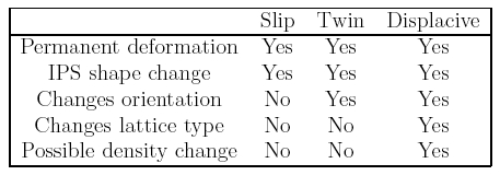
![\includegraphics[width=12cm]{Figa27.eps}](img262.png)