

First-wall materials in fusion power plants
Introduction
At a time when global energy demands are steadily growing, the need for energy sources that do not rely on fossil fuels is becoming increasingly obvious. Alternative sources of energy are required, to mitigate the effects of global warming in the short term, and to sustainably and cleanly continue to provide energy in the long term. Fusion power, generated by the combining of atomic nuclei at extremely high temperatures, has the potential to contribute greatly towards these demands (Lako et al., 1998). Presuming it is commercially and technically feasible, it is a CO2-free and virtually inexhaustible energy source.
There are, however, formidable engineering challenges still to be overcome in the design of such a power plant. Among these is the need to identify materials which will remain structurally reliable under exposure to the ferocious radiation emitted by the reaction plasma. The performance of these materials will, to a large extent, determine the commercial success (or failure) of a fusion power plant, by affecting plant reliability, refuelling and replacement downtime, and waste production; the thermal efficiency of the plant is also determined by the maximum allowable temperature in the first-wall structure. The problems faced by such a material are outlined below.
The current international “fast track to fusion” programme calls for a reactor to test control systems and plant engineering (the to-be-built International Thermonuclear Experimental Reactor, ITER) to run concurrently with a fusion-spectrum material irradiation facility (the International Fusion Materials Irradiation Facility, IFMIF, still to be agreed) (Konishi, 2004). These will be followed, around the 2040s according to current plans, by power-generating fusion plants—the set of present designs of the first (demonstration model) of which are collectively referred to as DEMO (Bloom et al., 2004).
Steady advances in the science and technology of fusion energy—both in materials issues and plasma control—have increased the possibility of demonstrating practical fusion power generation within the next fifty years. However, if these advances are consolidated, the prospect for fusion to markedly contribute to stabilisation and control of global CO2 emissions may be missed.
The first-wall environment
In ITER and future commercial magnetic confinement fusion power plants (such as the DEMO designs), the source of energy is the reaction between hot deuterium (symbol D) and tritium (symbol T) nuclei in a plasma chamber. To overcome the repulsion between atomic nuclei, the plasma is accelerated to energies equivalent to a temperature of around 100 million degrees Celsius. The reaction is:
The products of this reaction are alpha particles—helium ions, which are contained by the magnetic field—and neutrons—which are not. These neutrons, which have a characteristic energy peak around 14 MeV (with the remainder of the reaction energy given to the α particle), are absorbed in the surrounding material structure of the plant, transferring the heat of the reaction to an external cooling circuit and, ultimately, into electricity.
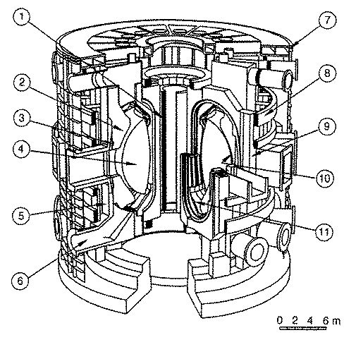
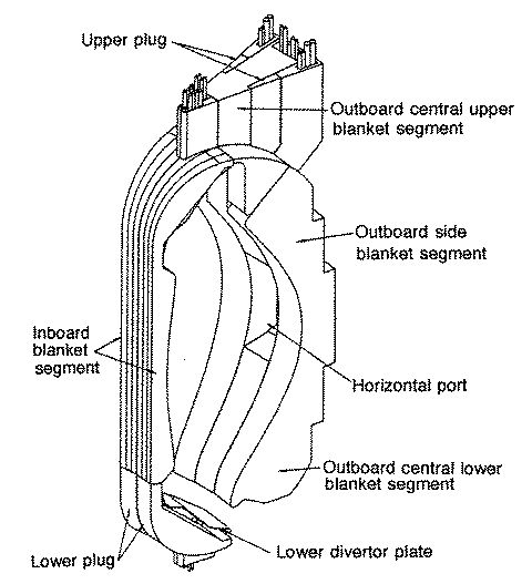
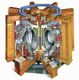
Figure 1.1: Left: Schematic diagram of a tokamak fusion reactor. 1: central solenoid; 2: shield/blanket; 3: active coil; 4: plasma chamber; 5: vacuum vessel shield; 6: plasma exhaust; 7: cryostat; 8: poloidal field coils; 9: toroidal field coils; 10: first wall; 11: divertor plates. Right: Schematic diagram of a first-wall/blanket segment around the plasma chamber (Smith et al., 1994).
This relentless bombardment of the first wall causes a number of problems for the material designer. Firstly, the temperature of the material is raised (the design operating temperature for a commercial reactor, based on the DEMO design, is in the region of 500–550 °C (Toschi et al., 2001)); secondly, as neutrons are not deflected by electrical fields, they can impact the atomic nuclei of the material, causing activation—that is, the material becomes radioactive, resulting in production of in situ helium (highly insoluble in steels, and a cause of embrittlement and void formation), and must be treated as radioactive waste once removed from service; and thirdly, atoms are knocked out of position throughout the material as the neutrons decelerate.
The last of these forms of damage severely disrupts the structure of the material, generating excess concentrations of vacancies and self-interstitials and increasing the dislocation density. These changes have strong effects on the mechanical properties of the material, and also on the diffusion rates of alloying species. It is calculated that, in the five-year design lifetime of a typical first-wall component, the material will experience displacement damage of up to 200 atomic lattice displacements per atom (dpa) [*] and will contain transmutation helium gas at levels of up to 2000 atomic parts per million (appm) (Ehrlich et al., 2000).
| Parameter / condition | ITER | DEMO-like reactor |
|---|---|---|
| Component replacements | None | 5-year cycle |
| Average neutron fluence (MW·yr·m−2) | 0.3 | 10 |
| Displacement damage (dpa) | 3 (SS) | 120 (RAFM) |
| Helium production (appm) | 30 | 1200 |
| Number of normal operation cycles | 30000 | <1000 |
| Surface heat flux (MW·m−2) | <0.5 | <1 |
| PFM operating temperature (°C) | Be: 200 - 300 | W: 550 - 700 |
| Primary functions of the blanket | Primary requirements of the blanket |
|---|---|
|
- Convert energy into sensible heat - Breed tritium for the fuel cycle |
- Adequate tritium production & recovery - Efficient heat recovery & operating lifetime - Acceptable post-irradiation environmental impact |
Activation of irradiated materials
As neutrons are uncharged particles, there are no significant repulsive forces between them and an atomic nucleus. Therefore, the chances of an atomic nucleus being directly hit by a neutron under irradiation can be high. On impact, the neutron may be absorbed by the nucleus, creating an unstable, radioactive atom. The process of an initially stable material becoming radioactive in this manner is termed activation.
The half-lives of resultant radionuclides can be thousands of years. The design code for fusion power plant structural steels calls for them to satisfy at least US Department of Energy Class C waste conditions—meaning the radioactivity should decay to an acceptable level within 100 to 500 years (Abe et al., 1994). The class of steels known as reduced activation ferritic/martensitic (RAFM) steels generally meets this criterion, as solvent Fe meets the class C limit. However, some typical steel alloying elements such as Mo, Nb, Ni, and N must be significantly reduced in concentration in these alloys as they form long-lived radionuclides. In general, the target limitation is configured as follows:
Where ci and ci,max are the actual and maximum permitted concentrations respectively. Niobium, for example, has a strict cmax threshold of less than 3 weight parts per million (wppm) (Butterworth and Giancarli, 1988).
| Element | Waste disposal limit | Recycle limit (100 yr) | Recycle limit (300 yr) |
|---|---|---|---|
| Ni | 15 - 38% | 87 - 470 wppm | 1.6 - 4.3% |
| Mo | 31 - 37 wppm | 3.6 - 20 wppm | 4.1 - 23 wppm |
| Nb | 2.4 - 3.5 wppm | 0.055 - 0.08 wppm | 0.055 - 0.08 wppm |
| Al | 660 - 3900 wppm | 13 - 79 wppm | 13 - 79 wppm |
Displacement damage
A neutron slows down within a first-wall material through impacts with atoms, producing a collision cascade as the atoms recoil. This results in a central core of the cascade which has a high density of vacancies, surrounded by a cloud of self-interstitial atoms (SIAs). The majority of these point defects rapidly annihilate with one another, but many remain to migrate into the bulk or form extended structures such as interstitial loops.
Figure 1.2: Defect arrangement showing vacancy-rich core and interstitial shell (Ullmaier and Trinkaus, 1996).
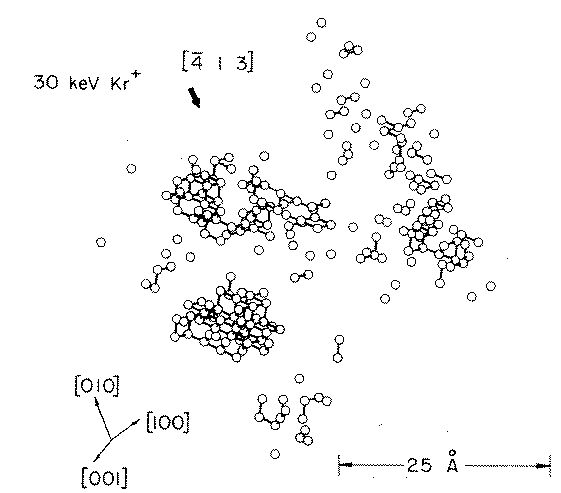
Figure 1.3: FIM observed vacancy structure of a cascade in tungsten (Wei et al., 1981).
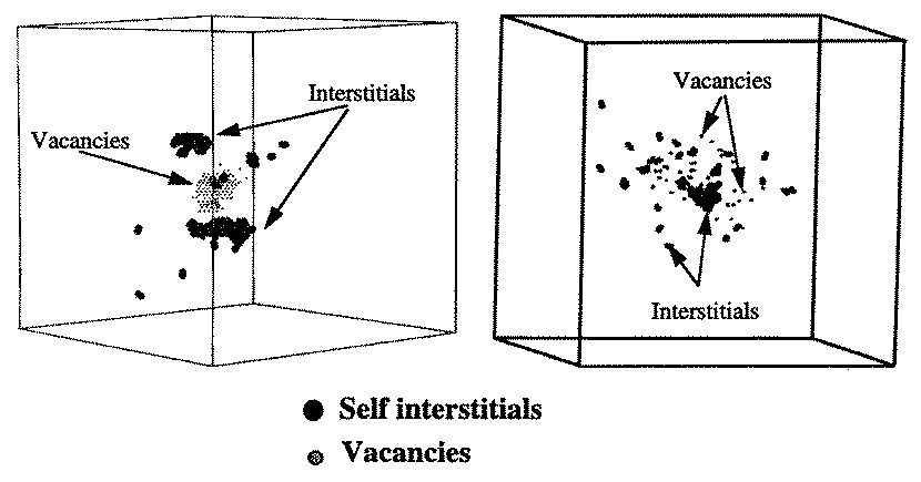
Figure 1.4: MD simulation showing distribution of vacancies (small dots) and interstitials (large dots) in Cu and Fe after 10 ps (Caturla et al., 2000).
Candidate first-wall structural materials
Several materials are under evaluation as candidate structural options:
- Vanadium alloys: The V-Cr-Ti system (specifically V-4Cr-4Ti) shows notable high-temperature strength, but thermal creep limits operation to ~700 °C and the irradiation database remains sparse.
- Ferritic/martensitic steels: Reduced activation 8–12 wt% Cr steels are the leading candidates due to lower void swelling compared to austenitic options (Garner et al., 2000). High-temperature creep limits exposure to ≤550 °C.
- Oxide dispersion strengthened (ODS) alloys: These consist of an ultrafine (~2 nm) dispersion of Ti-, Y-, and O-enriched oxide particles in a ferritic matrix, which dramatically improves creep resistance and introduces high-density microstructural traps for helium.
- SiCf/SiC composites: Silicon carbide fibre-reinforced matrices exhibit excellent strength retention above 1000 °C, but face challenges with transmutation gas production and structural hermeticity.
Irradiation hardening
Dislocation loops formed during collision cascades increase the overall dislocation density, hindering slip systems and causing the material to harden in a manner akin to cold work-hardening.
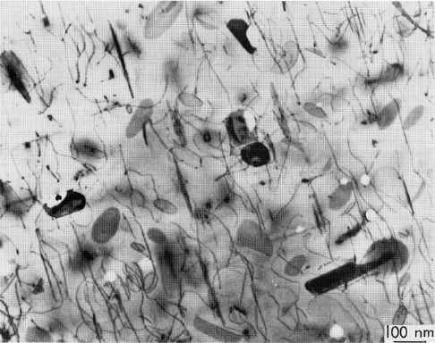
Figure 2.1: TEM micrograph of irradiated stainless steel at 10 dpa showing dislocation loops and voids (Mansur, 1994).
This behavior is mathematically defined via the dispersed barrier hardening framework:
Where M is the Taylor factor, μ is the shear modulus, b is the Burgers vector, and (N·d) represents the discrete obstacle density parameter. For superposed features, a root-mean-square combination is applied:
To simulate helium effects without a true fusion source, nickel is often deliberately added at ~2 wt% concentrations to simulate the correct transmutation gas ratio via thermal neutron multi-step reactions. However, this addition introduces complex compositional shifts that must be isolated using advanced non-linear tools like Bayesian neural networks.
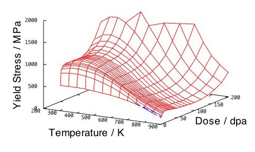
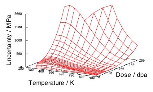
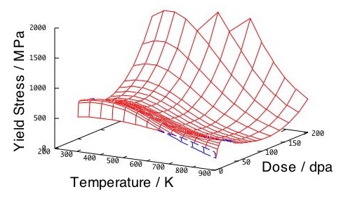
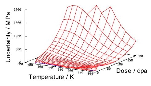
Figure 2.2: Neural network yield hardening predictions and associated modeling uncertainty envelopes for Eurofer97 ((a), (b)) and F82H ((c), (d)) steels as a function of damage level (dpa) and temperature.
Irradiation embrittlement
Embrittlement manifests during Charpy impact testing as an increase in the ductile-to-brittle transition temperature (ΔDBTT) and a drop in the upper shelf energy (ΔUSE).
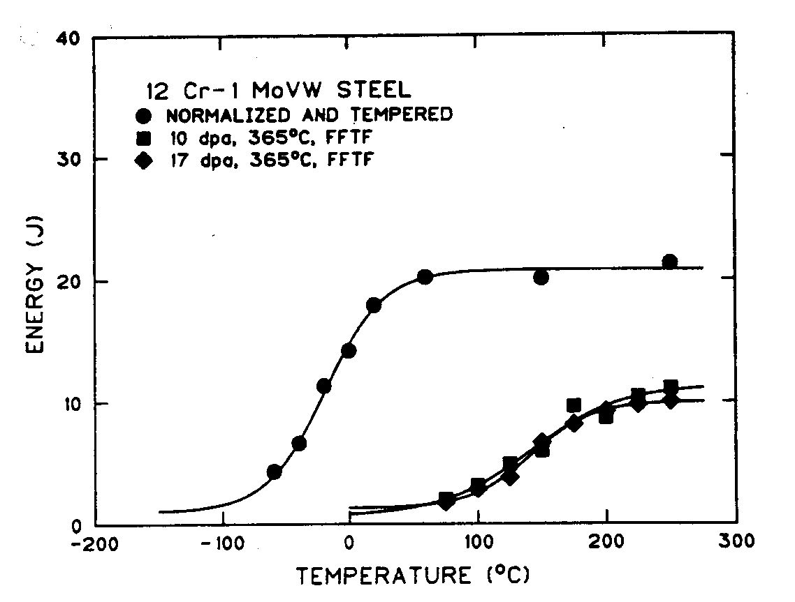
Figure 3.1: Charpy impact curves for a 12Cr-1MoVW steel before and after irradiation in a fast reactor environment (Klueh and Harris, 2001).
At temperatures below 400 °C, hardening embrittlement dominates, following the general proportionality trend of ΔDBTT = a · Δσy (where a varies between 0.33 and 0.7 depending on microstructural constraints). At higher temperatures, non-hardening embrittlement proceeds via radiation-enhanced segregation of impurity elements like phosphorus (P) to prior austenite grain boundaries.
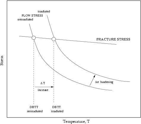
Figure 3.2: Schematic showing how an increase in yield flow stress shifting past a static cleavage fracture stress curve translates directly to a ΔDBTT shift.
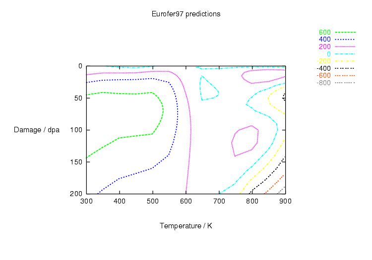
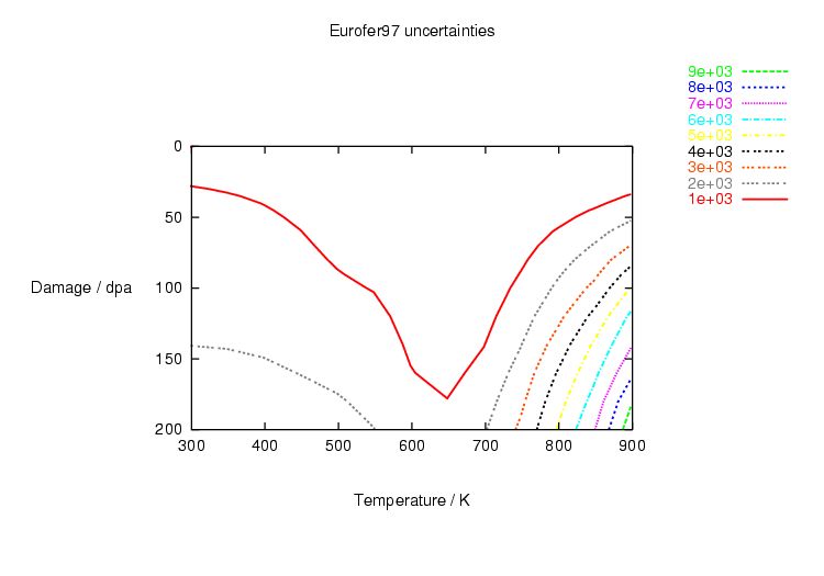
Figure 3.3: Model contour predictions and uncertainty boundaries for ΔDBTT in Eurofer97 steel (Kelvin scale).
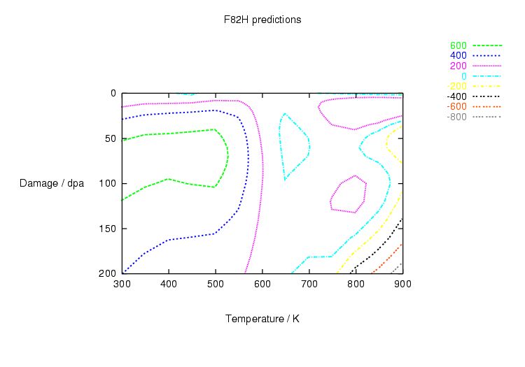
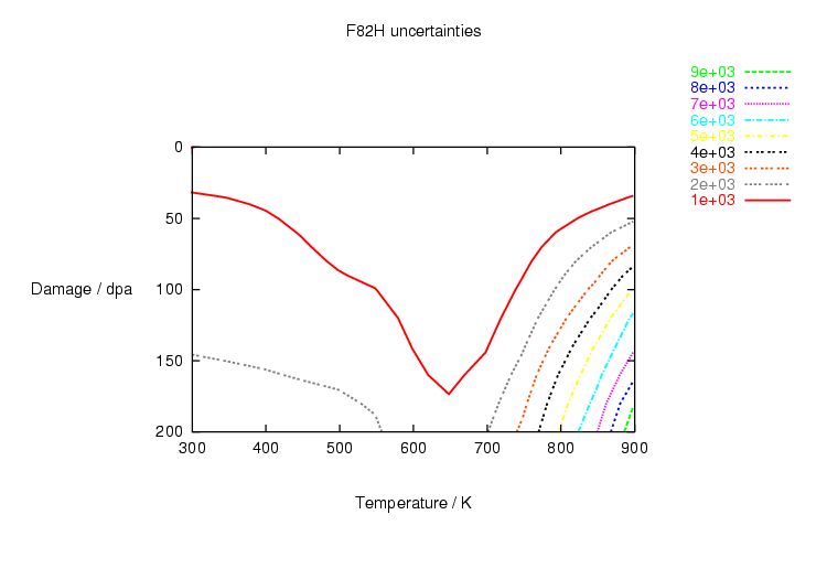
Figure 3.4: Model contour predictions and uncertainty boundaries for ΔDBTT in F82H steel (Kelvin scale).
Voids and bubbles in irradiated materials
Radiation-induced vacancies can coalesce to form large three-dimensional structural cavities, leading to severe macroscopic swelling that can completely distort structural dimensions.
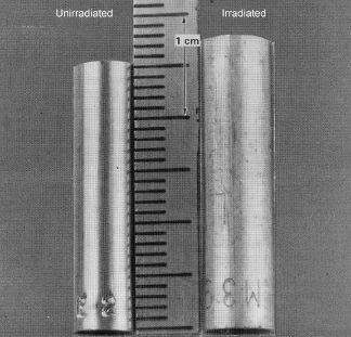
Figure 4.1: Volumetric swelling comparison of 316 stainless steel rods before (left) and after (right) rapid high-fluence irradiation (Mansur, 1994).
In this context, a cavity defines any generic internal hollow feature; a bubble represents a small cavity dynamically stabilised by high internal transmutation helium pressure; while a true void characterizes a cavity growing independently of gas stabilization where internal pressure satisfies the inequality condition:
To combat void growth, modern structural metallurgy targets the introduction of high-density nano-scale precipitates (as configured in mechanical alloyed ODS variants). These act as stable internal sinks that trap helium atoms uniformly throughout the matrix grains, preventing dangerous migration and gas segregation to the grain boundaries.
The International Fusion Materials Irradiation Facility
Because fission reactors fail to reproduce the high-energy 14 MeV neutron peak of a true D-T fusion plasma, the International Fusion Materials Irradiation Facility (IFMIF) is designed to bridge this testing gap. Using twin 40 MeV deuteron linear accelerators directed at a liquid lithium target, it will simulate a representative steady-state fusion irradiation spectrum to validate quantitative materials models for long-term power plant structural engineering.