Thermecmaster Thermomechanical Simulator
|
![[A logo showing the University of Cambridge Crest]](https://www.phase-trans.msm.cam.ac.uk/Univ.jpg)
|
Philip Opdenacker
The THERMECMASTOR-Z is a dilatometer that allows to make simulations of thermo-mechanical treatments on small cylinder samples. The samples must be 8 mm in diameter and 12 mm in length.
Extreme care must be taken while using this apparatus and safe use can be achieved by strictly applying the following instructions. Settings other than the ones mentioned should not be changed by the operator without extensive knowledge.
New Users
If you wish to use the THERMECMASTER, you should read the instructions below carefully and several times and also attend tests carried out by experienced users. When you feel you are ready to take the test, contact Philippe OPDENACKER to set up a test date. The test will last about 2 hours under supervision and you will have to perform safely and on your own 2 successive experiments. You will also be asked to switch the THERMECMASTER on and off before and after the test.
For use under load conditions, you will be asked to take another short test. A list of certified users will be attached to the THERMECMASTER.
When you become a certified user, don't forget to book your sessions in advance and to fill in the log book with your grant number after your session.
Instructions A: Switching On
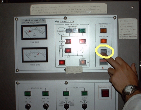
- Ensure that everything is switched off and that the vaccum system is operating properly i.e. the diffusion pump is on. The 2 red buttons on the left of the vaccum panel must be lit.
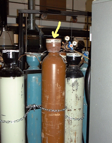
- Open the brown helium gas bottle. Helium is necessary for the cooling phase of the simulation cycles.
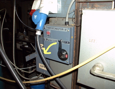
- Turn the power for the welder on.
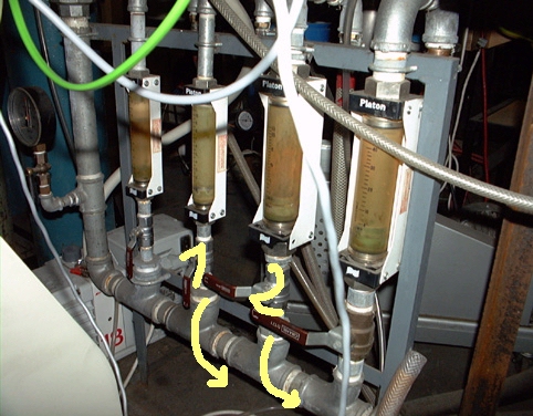
- Open 2 water taps on the right in the order: 2nd from the right, first from the right.
- Switch the PC on. Check that the system disk is in.
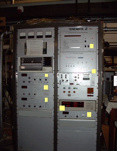
- Turn switches 1 to 7 on the main control panel on in that order (clockwise)
Instructions B: Design Experiment on PC
- Press "f1" + "f3"
- Press "f" : operation program
- Insert Setup floppy in drive # 2 and press "f": floppy in
- Using an existing setup, create a new one:
-Input existing setup name (not more than 8 characters)
-"V": verify data
-"C": correct
-"D": pattern data
-Input address: e.g. "1"
-Make modifications using the arrows : first column is address number, second is time, third is time multiplicator, fourth is temperature, sixth is to record data (Y or N), seventh is time to start or finish cooling.
-Go to V.end
-Store on disk: press "D"
-Pattern name is xxxxxx: OK? press "Y" to create new setup name or "N" to overwrite.
-Input new setup name.
-Is it OK? press "Y"
- Press "P": load to PSG (THERMECMASTOR)
- Press "4": select logger memory words!! 4kw
- Take note of the sampling time e.g. 262687. This number is required when saving the data on disk.
- Press return: is printer ready?
- Press number of repeat times for the cycle : most often: "1"
Very important !!!Before step 10, ensure that phase C-PUTTING THE SAMPLE IN THE CHAMBER is completed.
- Press "s" and return to start the experiment.
Instructions C: Placing Sample in Chamber
Warning: It is extremely important that the RAM is always off when you open the vaccum chamber, this to avoid accidents by unexpected moves of the RAM, which could break silicon dies and send debris all over the place or crush your fingers. Always shield yourself when the RAM is on with the chamber door.
Warning: in the same way, never leave the RAM on when you decide to switch the Thermec off (buttons 7 to 1 in that order- anticlockwise). If the RAM is on, it will reset with large amplitude moves that could break the dies or severely deform the inductor. The RAM on/off switch is called PUMP ON/OFF switch. It is located on the bottom right corner of the main control panel.
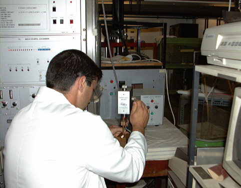
- Spotweld the thermocouple to your sample. Don't forget to turn the power off when you are done. The power setting depends on the type of materials but is generally set to 5 or 6.
- Stop the vaccum system by pressing the on/off button on the top right of the gas control panel.
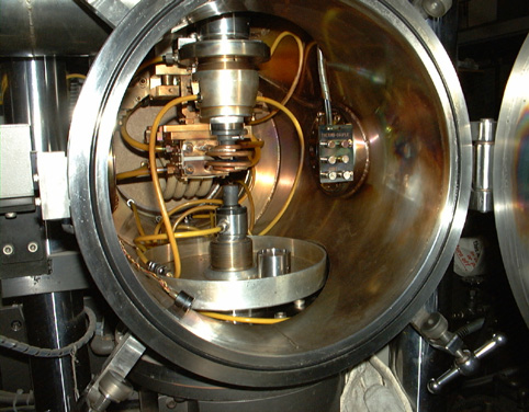
- Open the gas chamber valve and check that the pressure is increasing in the chamber on the main gauge. When close to ambient pressure, open the chamber. Check that there is no sample inside. Turn RAM on (with door closed!) to reset it. The displacement gauge should indicate -100, which is its higher position. If not, turn the RAM drive switch up to reach -100. Then, turn RAM off again, and reopen the chamber.
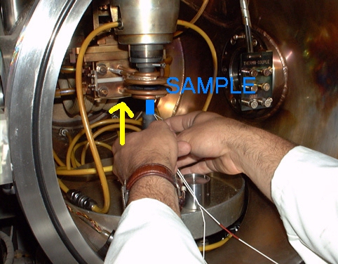
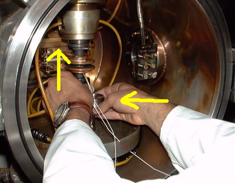
- Insert sample in place (Figure a, Figure b, Figure c, Figure d) carefully. At this stage, the main problem that can arise is a thermocouple wire breaking. Connect the red wire to the left and the other wire to the right. Then, check that the temperature reading is OK (around 10 to 15 degrees). If you invert the connections for the thermocouple wires, the temperature reading is negative. If you start an experiment in these conditions, the THERMEC will try and reach the target temperature by matching it to this negative reading. Therefore, it will give it its maximum power and the sample will melt. If this happens, press "emergency stop".
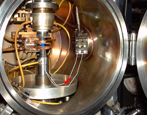
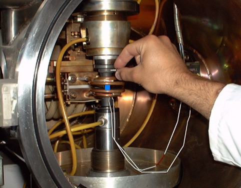
- Close chamber, turn RAM on, lower it and check the load gauge. When the load becomes positive (for a displacement value e.g -28.7), lift the RAM for a -5 displacement value (e.g. -33.7). (Picture ). Turn ram off, open chamber and remove the little screw (Picture)
- Close chamber, turn RAM on, activate the vacuum system. Check the thermocouple reading again.
- Leave it pumping down to the right vaccum, when the lower gauge's arrow is between the red and white labels. To reach this pressure, it takes about 15 minutes. To avoid waisting time, phase B) can be done after C) when the vaccum is being made in the chamber.
- Put filament on as well as power set to 8.
- Set sample diameter to the value indicated by using "nominal".
- Select one of the cooling options: auto1 for slow cooling or auto2 for faster cooling.
- Press "s". "Pattern generation" appears on the computer screen. Check that the temperature is following the pattern.
Instructiions D: After the Experiment
The vacuum system will be off automatically.
- Switch off RAM and filament. Bring back power set to zero.
- Open the chamber and put the little screw in place to hold the upper die.
- Close the chamber and turn RAM on. Lift RAM to its upper position (-100).
- Turn RAM off and open the chamber to get the sample.
Then there are two options:
- If this is your last run, close the chamber and start the vaccum again. Proceed to F)
- If you want to perform another run, start again at step D-4
Instructions E: Saving Dilatometric Data
This can be done after Instructions B.
- Press "C": transfer data to computer and insert system disk in drive 2 (for the moment ,drive 1 is not working).
- Press "A": Store data in ASCII
- Press "T": T-D store (Temperature-dilatation)
- Set data disk in drive 2.
- Input data name, not more than 8 characters.
- Press "4": 4 kW
- Press "0": Normal mode
- Input sampling time.
- Put experimental details.
- Wait about 2 minutes till data are finished being stored. If storage fails, reset computer and start transfering data again.
- Put back system disk in drive 2 and turn computer off.
- Press the "Clear button" on the top right corner of the control panel, turn on the PC and go back to phase B) if you want to do another run. If not, proceed to phase F)
Instructions F: End of Session
- Turn switches 7) to 1) off in that order on the control panel.
- Reposition dust-protecting cover on the control panel.
- Switch off water taps in reverse order (the one at the far right first) and the Welder power.
- Close the Helium gas cylinder.
- Come back 15 minutes later to check that the vaccum system has switched to the diffusion pump.