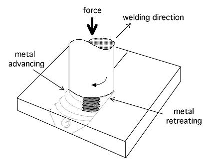

Friction stir welding, a process invented at TWI, Cambridge, involves the joining of metals without fusion or filler materials. It is used already in routine, as well as critical applications, for the joining of structural components made of aluminium and its alloys. Indeed, it has been convincingly demonstrated that the process results in strong and ductile joints, sometimes in systems which have proved difficult using conventional welding techniques. The process is most suitable for components which are flat and long (plates and sheets) but can be adapted for pipes, hollow sections and positional welding. The welds are created by the combined action of frictional heating and mechanical deformation due to a rotating tool. The maximum temperature reached is of the order of 0.8 of the melting temperature.
|
|
|
The tool has a circular section except at the end where there is a threaded probe or more complicated flute; the junction between the cylindrical portion and the probe is known as the shoulder. The probe penetrates the workpiece whereas the shoulder rubs with the top surface. The heat is generated primarily by friction between a rotating--translating tool, the shoulder of which rubs against the workpiece. There is a volumetric contribution to heat generation from the adiabatic heating due to deformation near the pin. The welding parameters have to be adjusted so that the ratio of frictional to volumetric deformation--induced heating decreases as the workpiece becomes thicker. This is in order to ensure a sufficient heat input per unit length.
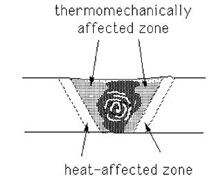
The microstructure of a friction-stir welddepends in detail on the tool design, the rotation and translation speeds, the applied pressure and the characteristics of the material being joined. There are a number of zones. The heat-affected zone (HAZ) is as in conventional welds. The central nugget region containing the onion-ring flow-pattern is the most severely deformed region, although it frequently seems to dynamically recrystallise, so that the detailed microstructure may consist of equiaxed grains. The layered (onion-ring) structure is a consequence of the way in which a threaded tool deposits material from the front to the back of the weld. It seems that cylindrical sheets of material are extruded during each rotation of the tool, which on a weld cross--section give the characteristic onion-rings.
The thermomechanically-affected zone lies between the HAZ and nugget; the grains of the original microstructure are retained in this region, but in a deformed state. The top surface of the weld has a different microstructure, a consequence of the shearing induced by the rotating tool-shoulder.
Further details of the process can be found in Joining of Commercial Aluminium Alloys, a paper published in the proceedings of an International Conference on Aluminium (INCAL 2003).
The process rapidly went into commercial production and has been tremendously successful in the welding of aluminium and its alloys. The picture below is of a ship containing twenty miles of friction stir welds, the joining done by Friction Stir Link, Inc.and Marinette Marine.
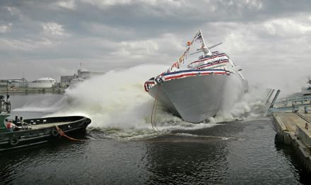
The launch of friction stir welded Littoral Combat Ship, September 2006. Reproduced with the permission of Chris Smith, Friction Stir Link, Inc. |
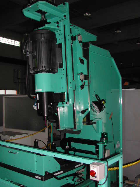
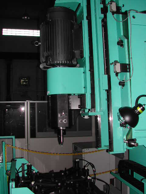
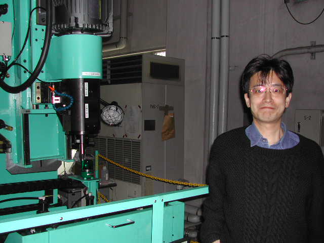
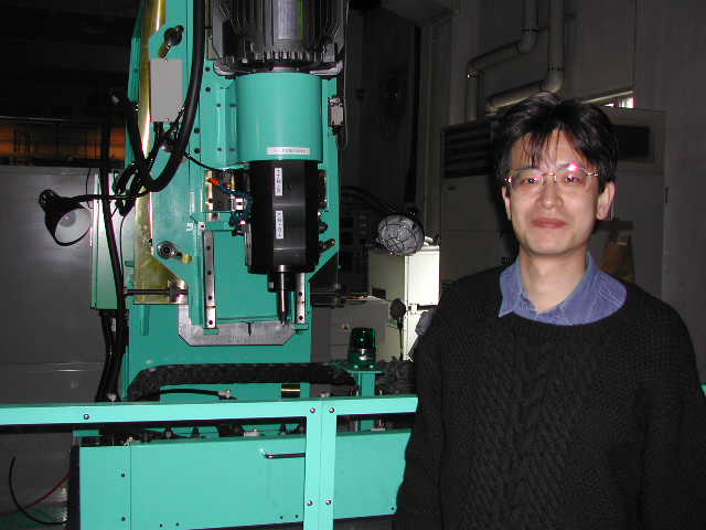
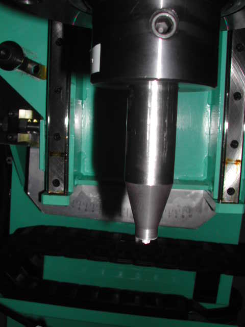
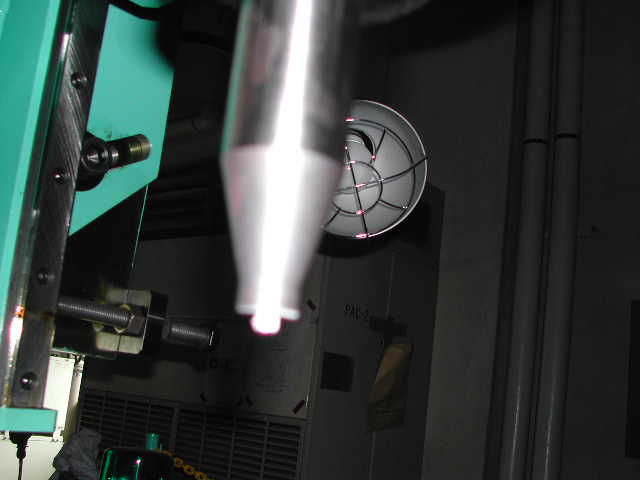
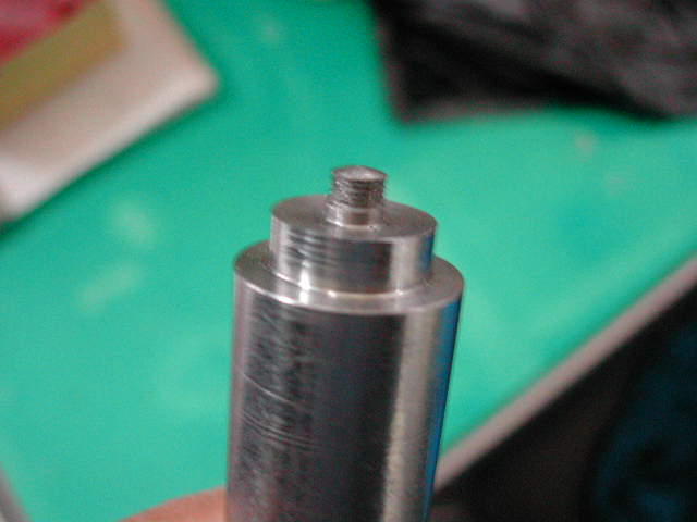
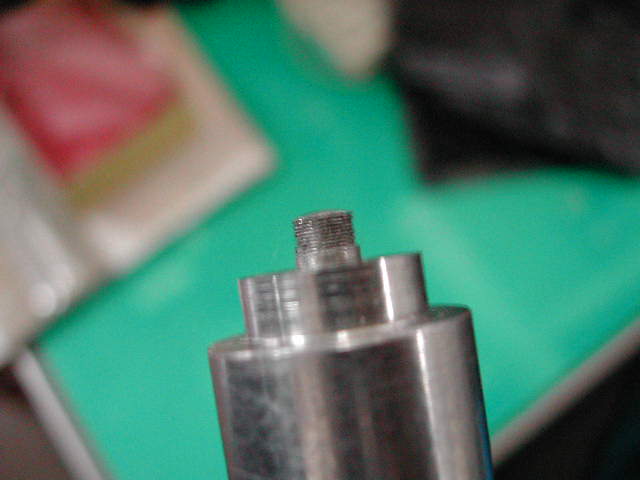
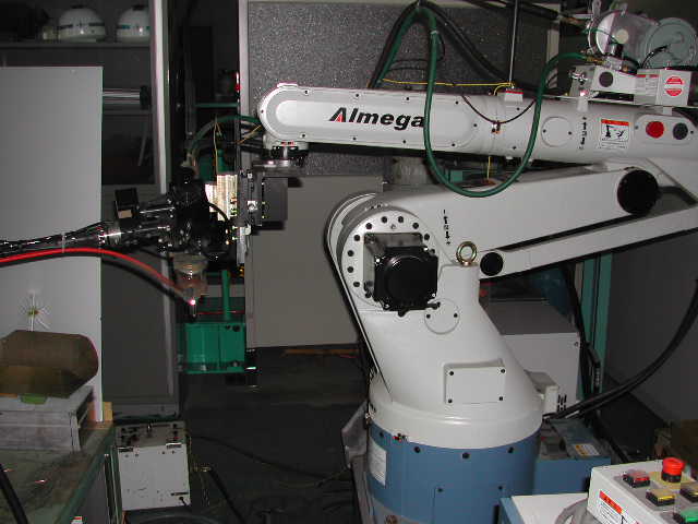
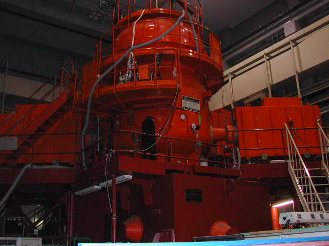
The six photographs below show a typical friction stir welding (FSW) machine. This one is at the Joining and Welding Research Institute (JWRI) of Osaka University, Japan. The photographs are taken with the permission of Professor Hidetoshi Fujii; they can be enlarged by clicking on the thumbnails. The last two photographs are a close-up of the tool, as mounted in the machine.
|
|
|
|
|
|
An illustration of some types of tools. Each tool has a shoulder whose rotation against the substrate generates most of the heat required for welding. The pin on the tool is plunged into the substrate and helps stir the metal in the solid state.
|
|
|
|
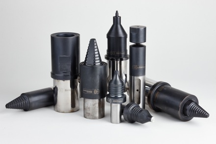
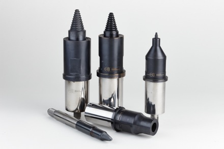
The following photographs from PTG Heavy Industries illustrate the different types of pin geometries used in their Powerstir Friction Stir Welders:
 |
 |
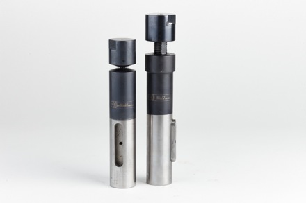 |
In excess of 40 different types of welding tool have been developed for thin walled structures, heavy & thick walled structures, self-adaptive bobbin tools, standard bobbin tools and retracting pin FSW tooling. On-going development work has resulted in a series of welding tools capable of jointing a wide range of materials, in particular: aluminium alloys, magnesium alloys, copper alloys, titanium alloys and steels. |
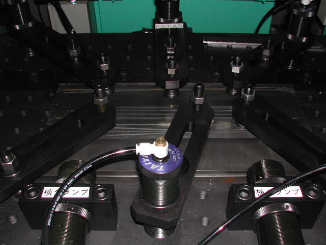
The two halves to be joined must be rigidly fixed before the welding operation (first picture below). The pin, which is an integral part of the tool, is plunged into the metal to help stir it up; the shoulder of the tool generates much of the heat. As the weld is completed, the tool is withdrawn. leaving behind a hole. The weld is designed so that such regions can be discarded from the component. The presence of a hole may not be appropriate when welding pipes or storage vessels. The hole can be avoided by designing the tool such that only the pin can be retracted automatically and gently into the shoulder, leaving behind an integral weld.
|
|
|
The following movies showing robotic friction-stir welding of complex shapes are reproduced for teaching purposes, with the kind permission of Dr Jorge F. dos Santos, GKSS Forschungszentrum GmbH, Institute for Materials Research, Joining Technology, Max-Planck-Str., D-21502 Geesthacht, Germany. Movie 8 has been provided by Megastir Technologies.
The following presentations are reproduced for teaching purposes, with the kind permission of Dr Leif Karlsson, ESAB AB, Sweden.
Steel can be friction stir weldedbut the essential problem is that tool materials wear rapidly. Indeed, the wear debris from the tool can frequently be found inside the weld. The process would therefore be used in special circumstances where other welding methods are inadequate. These circumstances have yet to be clarified. There are so many good methods by which steel can be welded. The example below is the FSW of 316L stainless steel. The weld is made by Hitachi of Japan, who have kindly provided the photographs via Professor Hiroyuki Kokawa and Sueng Hwan Park of Tohoku University. Notice that the sample becomes red-hot during welding..
|
| PDF file of image. |
Since the tool gets red hot, it is necessary to protect it against the enviroment using a shielding gas. The following movie illustrates the friction stir welding of interstitial-free steel, provided by Hidetoshi Fujii, Osaka University (JWRI), Japan. It takes a while before the plate becomes sufficiently heated to proceed with welding.
| FSW of steel | Video |
|
A possible use of FSW in the welding of steels is in the context of stainless steels [Klingensmith et al.]. Austenitic stainless steels can easily be welded using conventional arc welding and other processes. However, FSW can offer lower distortion, lower shrinkage and porosity. More important is the avoidance of fumes containing hexavalent chromium which is carcinogenic. In addition, chemical segregation effects associated with welding processes involving solidification are avoided. Such segregation can lead to a degradation of corrosion resistance since electrochemical cells are set up between solute-rich and poor domains.
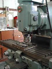
Friction-stir welding machine. |
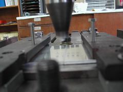
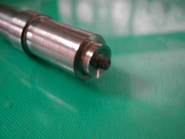
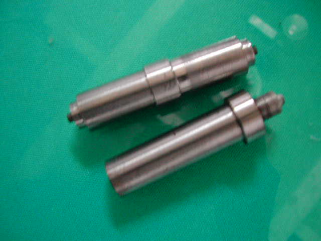
The tip of the steel tool. |
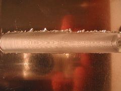
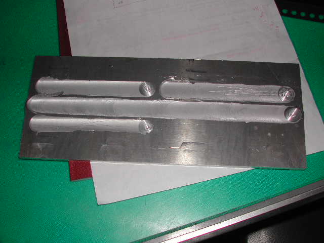
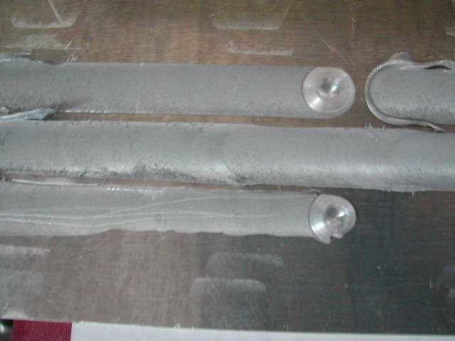
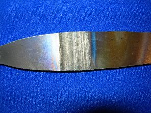
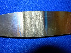
Friction stir-weld, butt joint between aluminium plates. |
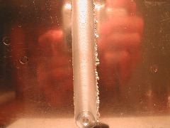
Friction stir-weld, butt joint between aluminium plates. |
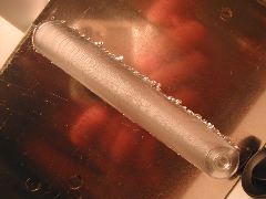
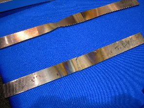
The hole at the end is where the operation terminated. Made at Tohoku University, courtesy of Sueng Hwan Park and Professor Hiroyuki Kokawa. |
| FSW of aluminium | Video |
|
The most popular aluminium casting-alloycontains about 8 wt% of silicon. It therefore solidifies to primary aluminium-rich dendrites and a eutectic mixture of aluminium solid-solution and almost pure silicon. The latter occurs as coarse silicon particles which tend to be brittle. The cast alloy usually has some porosity. Friction stir welding has the advantage that it breaks up the coarse silicon particles and heals any pores by the mechanical processing, as illustrated below.
|
|
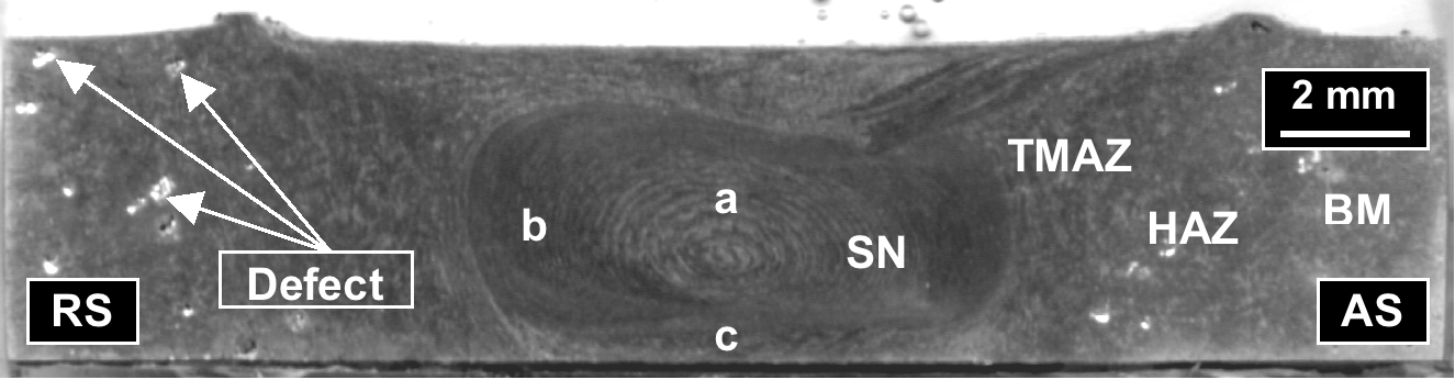
A section through a friction stir weld made in an Al-Si casting alloy. There are pores indicated in the base metal (BM). HAZ represents the heat affected zone, TMAZ the thermomechanically affected zone, and SN the stir nugget. The photographs in this section have kindly been provided by Professor H. Fujii of JWRI, Japan. |
|
|
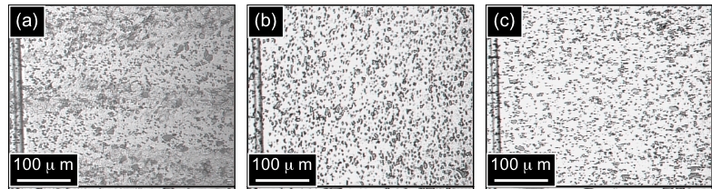
Optical micrographs showing the microstructure in (a) the base metal; (b) heat-affected zone; (c) the thermomechanically affected zone, where considerable refinement of the silicon has occurred. |
|
|
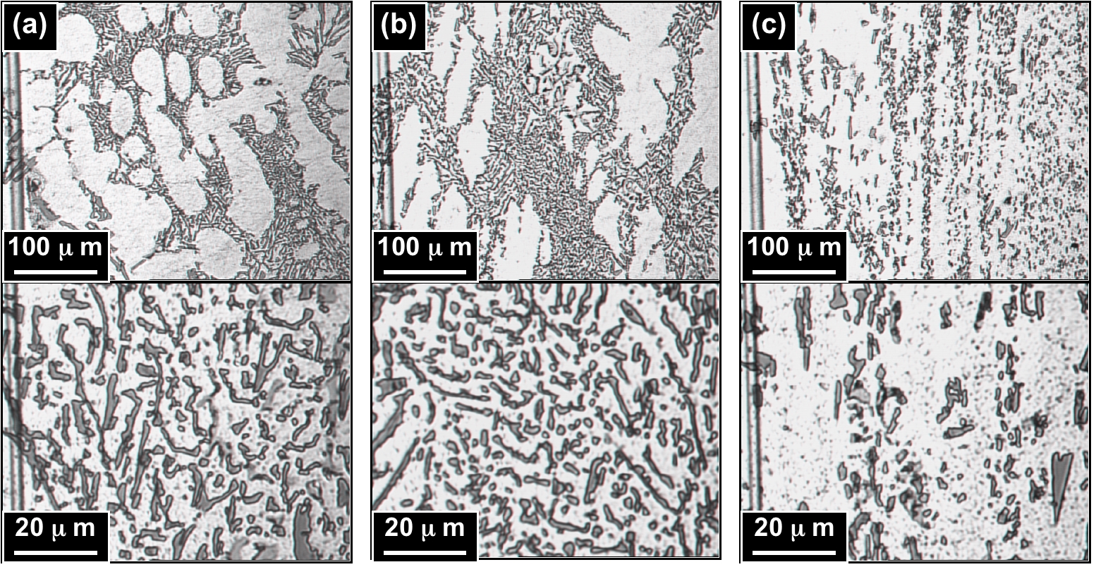
Optical micrographs of regions (a), (b) and (c) of the stir nugget. The location of these regions is identified in macroscopic section presented above. |
|
|
The refinement of silicon and elimination of porosity leads to better mechanically properties in the weld than in the base plates. |
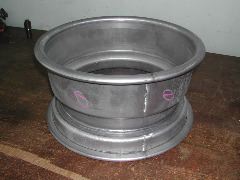
At the Metal Industries Research and Development Centre, Taiwan. This is a friction stir welded 5000 series aluminium wheel for a sports car. |
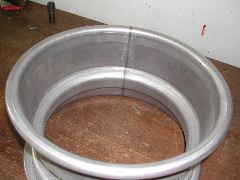
Inside view of a friction stir welded 5000 series aluminium wheel for a sports car. The FSW is carried out as a seam weld on a cylinder, followed by the forming operation. |
In friction stir welding, the tool has a shoulder and a pin. Much of the heat is generated by the interaction of the shoulder with the work piece, and the shoulder also has a forging action which confines the material. The pin does the stirring which leads to a joint.
In thermal stir welding (TSW), a process invented at NASA, the heat source, pin and forging operations are physically separated. Heating is via an induction coil so that the temperature of the workpiece can be independently set. The tool is a pin without a shoulder, and is followed by a set of forging rolls.
One purpose of this process which is currently in the development stage is to weld thick plates of titanium. In FSW, the temperature gradients that arise as a function of depth given different material flow properties and the method has not succeded in making defect free and reliable welds in thickness greater than 12 mm. This might be possible using the TSW process.
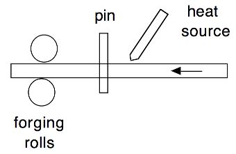
Schematic of TSW |
Thermal stir weld in Ti |
Thermal stir weld in Ti |
Thermal stir welding |
The images below have nothing to do with friction stir welding. The first picture shows a hybrid laser-arc process in which both a laser and an electric arc are used to achieve penetration. The other picture shows a massive electron beam welder. Both are located at JWRI, Osaka University.
|
|
|
|
|
|
|
| Superalloys | Titanium | Bainite | Martensite | Widmanstätten ferrite |
| Cast iron | Welding | Allotriomorphic ferrite | Movies | Slides |
| Neural Networks | Creep | Mechanicallly Alloyed | Theses |
| PT Group Home | Materials Algorithms |

|

|