
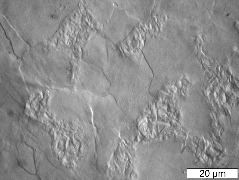
Fig6
Surface relief in Fe-0.16C-0.26Si-0.96Mn-0.11Cr-0.12Ni-0.02Mo wt% sample, following laser surface-treatment at 10 mm/s, which resulted in partial austenitisation. The sample here is away from the centerline of the laser track. The regions of pearlite which transformed into austenite in the heating cycle, changed into martensite during cooling, resulting in surface displacements. The remainder of the microstructure is ferrite. Hardness 220 HV
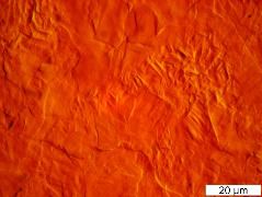
Fig7
Surface relief in Fe-0.16C-0.26Si-0.96Mn-0.11Cr-0.12Ni-0.02Mo wt% sample, following laser surface-treatment at 10 mm/s which resulted in partial austenitisation. The sample is located at the centerline of the laser track. The regions of pearlite which transformed into austenite in the heating cycle, changed into martensite during cooling, resulting in surface displacements. The remainder of the microstructure is ferrite. Hardness 296 HV
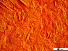
Fig8
Surface relief in Fe-0.16C-0.26Si-0.96Mn-0.11Cr-0.12Ni-0.02Mo wt% sample, following laser surface-treatment at 5 mm/s which resulted in a much greater degree of austenitisation. The sample is located at the centerline of the laser track. The regions of pearlite which transformed into austenite in the heating cycle, changed into martensite during cooling, resulting in surface displacements. There is only a small quantity of ferrite. Hardness 410 HV
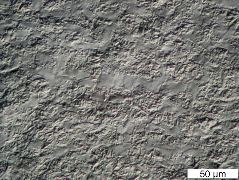
Fig9
Surface relief in Fe-0.46C-0.21Si-0.74Mn-0.10Cr-0.08Ni-0.01Mo wt% sample, following laser surface-treatment at 10 mm/s which resulted in partial austenitisation. The sample is located away from the centerline of the laser track. The regions of pearlite which transformed into austenite in the heating cycle, changed into martensite during cooling, resulting in surface displacements. The smooth parts of the relief correspond to ferrite from the original microstructure. Hardness 440 HV
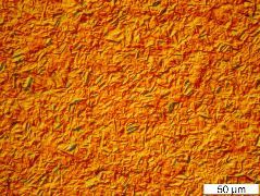
Fig10
Surface relief in Fe-0.46C-0.21Si-0.74Mn-0.10Cr-0.08Ni-0.01Mo wt% sample, following laser surface-treatment at 10 mm/s which resulted in complete austenitisation. The sample is located at the centerline of the laser track. The austenite then transformed into martensite during cooling, resulting in characteristic surface displacements. Hardness 715 HV
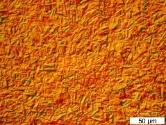
Fig11
Surface relief in Fe-0.46C-0.21Si-0.74Mn-0.10Cr-0.08Ni-0.01Mo wt% sample, following laser surface-treatment at 5 mm/s which resulted in complete austenitisation. The sample is located at the centerline of the laser track. The austenite then transformed into martensite during cooling, resulting in characteristic surface displacements. Hardness 744 HV
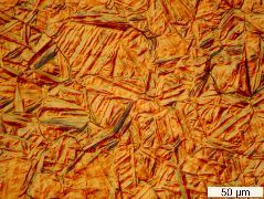
Fig12
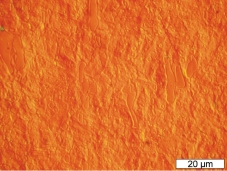
Surface relief in Fe-0.44C-0.34Si-0.70Mn-01.10Cr-0.16Ni-0.18Mo wt% sample, following laser surface-treatment at 5 mm/s which resulted in complete austenitisation. The sample is located at the centerline of the laser track. The austenite then transformed into martensite during cooling, resulting in characteristic surface displacements. Hardness 748 HV
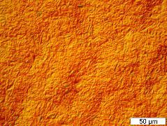
Fig13
Surface relief in Fe-0.44C-0.34Si-0.70Mn-01.10Cr-0.16Ni-0.18Mo wt% sample, following laser surface-treatment at 10 mm/s which resulted in complete austenitisation. The sample is located at the centerline of the laser track. The austenite then transformed into martensite during cooling, resulting in characteristic surface displacements. Hardness 767 HV
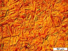
Fig14
Surface relief in Fe-0.44C-0.34Si-0.70Mn-01.10Cr-0.16Ni-0.18Mo wt% sample, following laser surface-treatment at 5 mm/s which resulted in complete austenitisation. The sample is located at the centerline of the laser track. The austenite then transformed into martensite during cooling, resulting in characteristic surface displacements. Hardness 748 HV
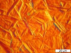
Fig15
Surface relief in Fe-0.44C-0.34Si-0.70Mn-01.10Cr-0.16Ni-0.18Mo wt% sample, following laser surface-treatment at 5 mm/s which resulted in complete austenitisation. The sample is located at the centerline of the laser track. The austenite then transformed into martensite during cooling, resulting in characteristic surface displacements. Hardness 748 HV
Chromium carbides
This is a sample from an 11.5Cr 1.1C wt% steel which has martensite but it also illustrated undissolved chromium carbides.

