Structural Integrity Assessment of Engineering Components
Afshin Motarjemi and Amir Shirzadi
Background
Integrity is a term which refers to the quality of being whole and complete, or the state of being unimpaired [1,2]. Structural Integrity Assessment is an approach to assess whether a structure is fit to withstand the service conditions safely and reliability throughout its predicted lifetime.
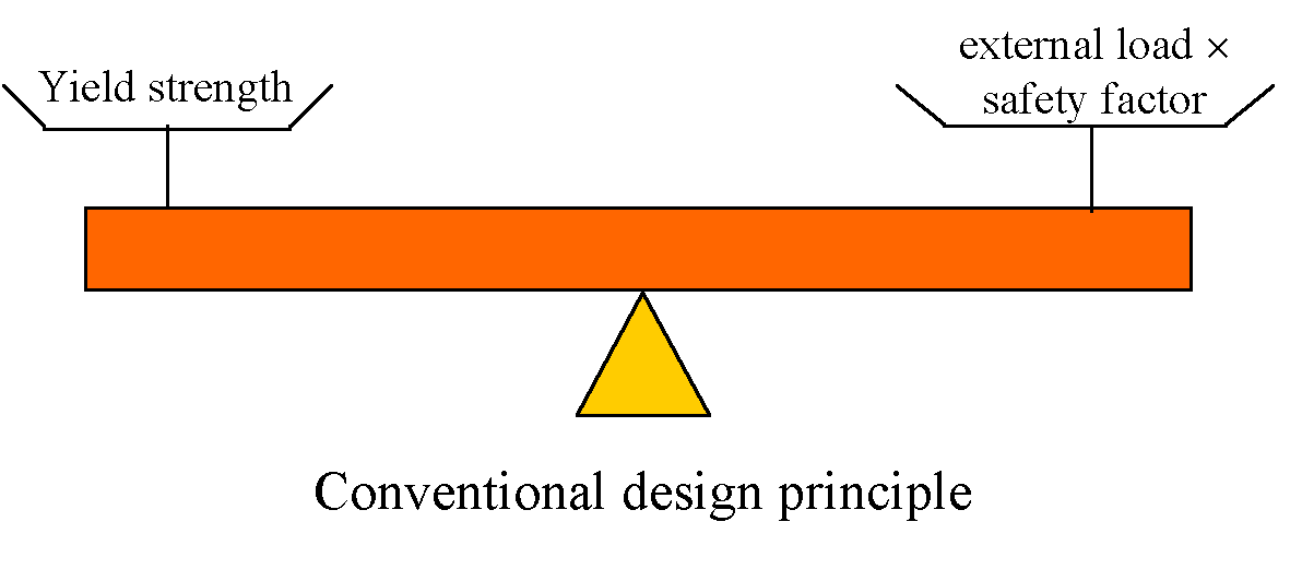
Established philosophy behind the design of any structural component is to ensure that the strength of the material, of which the component is made of, is higher than the maximum applied stress in service. If the former appears to be greater than the latter, then the component is considered to be fit for service, otherwise, modification in design or the use of another material with a higher strength is required.
|
In the conventional design approach, maximum applied stress should not exceed a certain fraction of the yield strength (i.e. elastic limit) of the material used. The ratio of the yield strength to the applied stress is often called safety factor, typically in order of 1.5 to 3. This approach is based on the assumptions that (1) the component is free from any flaws and defects and (2) the safety factor would compensate for any unexpected overloading or deterioration of the component during its service life.
|
 |
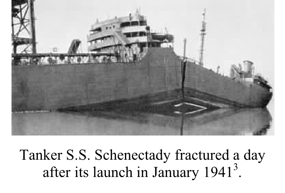
The components and welded joints in engineering structures, e.g. bridges, Ferris Wheels or a car chassis, may contain flaws and defects, which can compromise the strength of the structure drastically. Until early 19th century, the design engineers relied on using large safety factors in order to overcome the uncertainty associated with the actual strength of various components and their joints due to inevitable and undetectable internal defects. However, the catastrophic failure of some the naval ship and tankers in cold seawater during World War II, led to a broad research program in order to find out the cause of such failures.
|
These catastrophic failures were attributed to the presence of crack-like flaws in the welded joints, the use of steels with a low resistance to crack propagation (particularly in cold sea water) and poor joint design.
Hence, researchers tried to understand the mechanisms of such brittle fractures, which apparently occurred due to the presence of crack-like flaws in the weldment and bulk steels. Substantial amount of experimental and theoretical work on failure mechanisms was undertaken in mid 19th century. This was the beginning of a new field in engineering called Fracture Mechanics.
|
 |
The Eiffel Tower is more that 115 years old and was designed and built long before the engineers started developing the basic concepts of fracture mechanics. However, such yield-point-based designs, which incorporate high safety factors, are not an optimum approach for all engineering structures. Optimum selection and use of structural materials in order to reduce the weight, manufacturing and running costs of almost all engineering structures, requires profound understanding of failure mechanisms.
Fracture mechanics
In fracture mechanics-based approach, unlike yield point-based design approaches, a material should withstand the maximum applied load when of a crack-like flaw exists. In this approach, material resistance is expressed in terms of tensile properties (yield and tensile strengths) and fracture toughness (resistance of a material against any crack growth). However, applied load/stress is expressed in terms of crack-tip loading parameters, such as Kapplied, applied or Japplied. For linear elastic materials K, and for non-linear elastic and elastic-plastic materials or J are applicable. These parameters are defined in the following sections.
 |
| Different material behaviours during loading |
Stress Intensity factor K
K is a function of the applied stress , crack size (depth or length) and the geometry of the component or specimen:
Here Y is a compliance function dependent on the specimen geometry, calculated using finite element methods and available in standard tables.
Crack-tip opening displacement
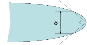
The crack-tip opening displacement (CTOD) or is another crack-tip loading parameter, a measure of the displacement which occurs at the crack tip. It is associated with crack extension, or blunting, under the influence of an externally applied stress.
Two different definitions exist for CTOD: opening displacement of the original crack tip or the displacement at the intersection of a 90* vertex with the crack flanks.
 |
 |
| Opening displacement of original crack tip |
Displacement at the intersection of a 90* vertex with the crack flanks |
J-integral
The J integral is the amount of energy required to grow an initial crack of length a by an increment a. It is another form of crack-tip loading parameter or fracture toughness. J is normally expressed in terms of a closed-loop integral, which needs to be estimated using finite element analysis. There are experimental techniques to measure J. Similar to CTOD, J is valid for non-linear elastic or elastic-plastic materials.
Brittle fracture assessment
Brittle fracture assessment considers the presence of crack-like flaws and hence it requires information about the existing flaws, in addition to tensile properties, fracture toughness and applied stress, as illustrated below.
Fracture mechanics-based integrity assessments require the following competences:
- Someone who can address materials issues.
- An engineer to estimate applied and residual stresses experimentally or by modelling.
- A non-destructive testing expert to detect the size and location of any flaws in the structure.
- A structural integrity expert to assess the fitness of the structure for service.
To carry out a brittle fracture assessment, the above information should be implemented into one of the established assessment procedures, as listed in the following Table, by a structural integrity engineer. The outcomes of the assessment is normally presented as maximum tolerable crack-like flaw size, permissible applied load and minimum fracture toughness for the material used.
Selection of an appropriate procedure depends on the mode of failure (fracture, fatigue, corrosion or creep), type of the component (pressure vessel, piping, etc.), service temperature and the experience of the user. Some of the above procedures are specific to a certain industry, such as R54 or R65, which have been developed for the nuclear industry, whereas the others such as BS 79106 have more general applications.
Two criteria are important to fracture assessment:
- Susceptibility to brittle fracture: a component/material is prone to brittle fracture if the applied loading exceeds materials resistance to brittle fracture.
- Susceptibility to plastic collapse: an un-cracked component/material is prone to plastic collapse if the applied stress exceeds materialaAeos tensile strength. However, at the presence of a crack, a component is susceptible to local plastic collapse if the stress on the ligament ahead of the crack REF exceeds a factor of yield (Y) or flow stress (U), defined as L:
| REF / Y > L where L = 0.5(1 + U / Y) |
Failure assessment diagram
To conduct a brittle fracture assessment, both the brittle fracture and plastic collapse parameters are implemented in a diagram called a failure assessment diagram (FAD). This is an essential tool for an integrity engineer to assess the fracture integrity of a component.
 |
Each of the two axes on a failure analysis diagram represents a failure mode, for example, brittle fracture (Kr) on the vertical axis and plastic failure (Lr) on the horizontal axis. The stress intensity ratio Kr=Kapplied/KI where KI is the fracture toughness. Similarly, Lr is the ratio between a reference stress and Y. The point Lr=Lrmax corresponds to a maximum allowable plastic collapse. Whether or not a structure is considered safe therefore depends on the level of applied stress, the crack size, geometry and properties such as fracture toughness and strength. If inside FAD (point A), the condition is acceptable, while a point such as C represents and unsafe design. A point exactly on the envelope (point B) presents a limiting condition.
Fatigue life assessment
Materials subjected to fluctuating stresses may fail even if the maximum applied stress is well below their yield strengths. This type of fatigue failure, accounts for at least 75% of all machines and structures [7].
The first investigations of fatigue failure date back to 1830 when a railway engineer in Germany, Woehler, carried out a series of systematic tests on train axles. Woehler managed to develop a relation between the magnitude of applied cyclic stress and the number of the cycles that a component could withstand before complete failure. Most fatigue data are, following Woehler, plotted as the applied cyclic stress S versus the number of cycles to failure N, to give the so-called S-N curves.
High cycle fatigue (N > 105 cycles) normally occurs when the applied stress is below the elastic limit of the material. Ferrous alloys normally show a plateau in their high cycle fatigue S-N curves, which define the endurance limit of the alloy. The origin of this is in strain-ageing due to interstitials pinning dislocations. There is no endurance limit for non-ferrous alloys, although aluminium-magnesium alloys, where the Mg is mobile, do exhibit the limiting stress.
Considerable research has been conducted on understanding fatigue failure mechanisms, and it is proven that such failures begin with slow growth and propagation of pre-existing cracks or defects, under the influence of fluctuating stresses. Once the crack reaches a critical size, the remaining cross-section cannot withstand the applied stress, leading to sudden and complete failure.
|
Fatigue failure can be recognized from the appearance of the fracture surface, which consists of a smooth region, due to the rubbing action during the crack propagation stage, and a rougher region (mostly in metals) which indicates the location of final and sudden rupture of the weakened component. The progress of the crack-front is indicated by a series of rings (beach marks) normally starting from a surface defect and progressing inward.
|
 |
Fatigue is a complicated phenomenon. The following parameters tend to influence the fatigue life:
- Materials properties such as the yield strength and fracture toughness.
- Magnitude, pattern and frequency of the applied cyclic stress e.g. its mean value, upper and lower limits and whether both limits are positive or both negative;
- Size of the internal and surface defects and their orientation relative to the direction of applied stress;
- Presence of stress concentration and/or residual stresses;
- Service temperature;
- Corrosion and consequent change in metallurgical structure.
Typical fatigue cycles may follow a sinusoidal pattern with or without zero mean stress. More complicated and irregular stress cycles are expected in the case of certain components such as aircraft wings and fuselage.
The mean stress amplitude m varying by a, and the algebraic difference between the maximum and minimum stresses in a cycle r all should be considered when conducting a fatigue life assessment.
Fatigue life assessment based on S-N curves
Engineers specialising in structural integrity assessment may use S-N curves to assess the fatigue life of a component or a structure. The assessment process starts with the collection of data, including manufacture and service histories. The magnitudes of applied loads, material properties and manufacturing processes all must be given to the assessor who then selects a suitable S-N curve. The fatigue life is then specified by estimating the number of cycle to failure.
Fatigue life assessment based on crack growth rate
S-N curves are generated by testing polished specimens which are essentially free from surface defects. However, most engineering structures/components contain a variety of defects so it is appropriate to assess life based on their ability to reach critical size. The crack growth with each cycle defines a rate which can be measured in independent tests as a function of the stress intensity range.
The steady-state growth rate is defined by the Paris equation:
where K is the stress intensity range Kmax - Kmin, C and m are material constants. The exponent m is usually between 3 and 4.
A minimum threshold of the stress intensity range is required before any crack propagation starts. Beyond this, crack growth occurs in three regimes. In the first, (I), only a small amount of crack growth occurs. This is followed by the steady region (II), where most of the fatigue life is consumed - there is a linear relationship between the crack growth rate and the logarithm of K. The third zone is associated with a very rapid growth of the crack due to the substantial loss in the cross section, leading to final fracture.
Fatigue life assessment, then follows the following analysis:
If Nf turns out to be higher than the number of cycles within the service life, then the structure can be considered safe in fatigue.
References
- www.dictionary.cambridge.org
- www.dictionary.com
- Deformation and fracture mechanics of engineering materialsaAeu Richard W. Hertzberg, 2nd edition, 1983, John Wiley and Sons, USA.
- R5 Assessment procedure for the high temperature response of structures, Issue 3, British energy, Gloucester, UK.
- R6 Assessment of the Integrity of Structures containing Defects, Revision 4, British energy, Gloucester, UK.
- BS7910, Guide on methods for assessing the acceptability of flaws in metallic structures, British Standard Institute, 2005, London, UK.
- Mechanics of MaterialsaAeu P.P. Benham et al., 2nd edition 1996, Pearson Education Limited, England.
Acknowledgment
The creation of this document was supported by the Higher Education Funding Council for England, via the U.K. Centre for Materials Education.


