Only some 60 years after the invention of the jet engines, flying has become a conventional method of transportation. Once the exclusive privilege of the 'swagger rich', it has become as much of a commonplace as a bus trip to the city centre (and in fact, the comfort and service onboard some of the cheapest airlines push the analogy further).
Yet, back in the early 1940s, many were seeing jet-powered flight as no more than a 'laboratory experiment' (maybe in the same way as we may be, today, sceptical about future applications of the recent 'scramjet').
These doubts were not unfounded: materials used in parts of the engine could not survive more than a few hundred hours at then relatively modest temperatures.
By the 1950s however, jet fighters were first put in combat over Korea. At the end of the 1960s, commercial jets were accepted, and by the end of the 1980s, the commercial aviation market overtook the military one.
The efficiency of commercial airliners has increased beyond all early expectations, and while it would probably be unfair to single out one factor, improvements in engine materials certainly played a key role.
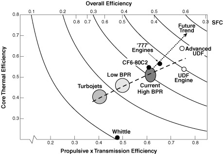
Evolution in engine efficiency, after Pratt & Whitney. Obtained from this page.
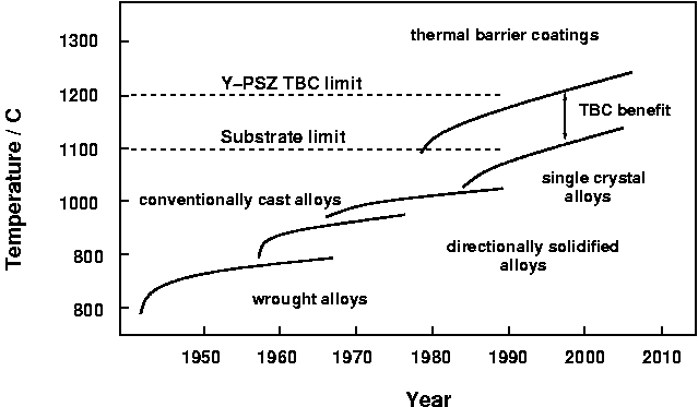
Increase in operational temperature of turbine components. After Schulz et al, Aero. Sci. Techn. 7:2003, p. 73-80.
Economical and, today, environmental concerns continue to provide impetus for operating the engines at ever increasing temperatures, thereby improving the thermodynamic efficiency and reducing pollutant emissions.
In its early years, the quest for higher temperatures was dominated by materials and processes developments. The apparition of superalloys in the early 1950s, considerable amelioration in casting technologies and, in the 1960s, the cooling system for turbine blades were all major steps forward, each allowing the service temperature to be increased by 20 °C or more.
Over the past 20–30 years, alloy improvement, directional and single-crystal solidification have contributed significantly, but, arguably, the emphasis has shifted to coating systems which have allowed an increase of gas temperature of up to 110 °C.
Coatings in gas turbines serve a variety of purposes, whether in jet engines, land-based power generation turbines or marine engines. A first requirement to operate turbines at higher temperatures was, of course, improved strength. Unfortunately, these conditions also mean severe oxidation/corrosion problems, and to make things worse, the improvement in mechanical properties of the base alloys was made at the expense of environmental resistance.
The first purpose of coatings was therefore to palliate for the poor oxidation resistance of the base alloy (aluminide, Pt-aluminide, MCrAlY). A second type of coatings applied to high-temperature parts are known as thermal barrier coatings (TBC). These are ceramic coatings with very low thermal conductivity. Despite being typically 1/5 mm thin, they allow for a drop of 100–300 °C between the gas and metal surface temperatures. Such coatings, however, are 'oxygen transparent' and do not prevent oxidation of the underlying substrate.
The gas turbine
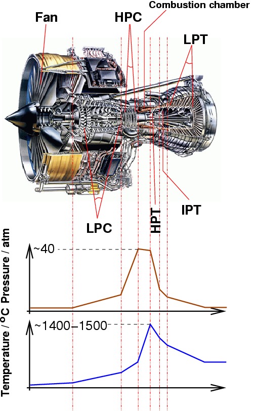
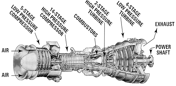
To discuss the role and use of coatings, it is necessary to first have a look at a gas turbine (below, a jet engine) and get an idea of the different problems the materials encounter.
A jet engine (Rolls-Royce Trent 800), showing the different stages: intermediate pressure compressor (IPC), high pressure compressor (HPC), high pressure turbine (HPT), intermediate pressure turbine (IPT), low pressure turbine (LPT), and the pressure and temperature profiles along the engine.
Image of the Trent 800 courtesy Rolls-Royce Plc. Diagrams after Michael Cervenka, Rolls-Royce.
An excellent and simple description of the functioning of a jet engine can be found on the Rolls-Royce website: Journey through a jet engine. General Electric also has a slightly more detailed yet fun demo.
Land-based gas turbines as used in the power generation industry are in principle very similar, but larger, and the actual turbine (the last rows of blades in the engine) is not connected with the rest of the engine, but drives a generator. In some cases however, a first turbine does drive the compressor, while a second is connected to a generator (power generation) or power shaft (marine engine).
A gas turbine for marine propulsion, with a two-stage turbine, the first one driving the compressor, the second providing the power. From this page.
Materials in gas turbines
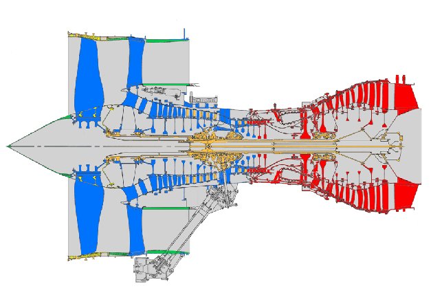
As visible in the temperature and pressure profile, the conditions in the gas turbine vary widely. Different materials are therefore chosen for different parts, as illustrated below:
The different materials used in a Rolls-Royce jet engine. In blue, titanium is ideal for its strength and density, but not at high temperatures, where it is replaced by nickel-based superalloys (red). In orange: steel used for the static parts of the compressor. Image courtesy Michael Cervenka, Rolls-Royce
In this case, 'low temperature' blades are made of titanium alloys, while high temperature components use Ni-base superalloys. The most severe conditions are met in the first row of the turbine. The entry temperature is around 1400 °C. Temperatures are kept lower at the surface of the blade because of the cooling system (ceramic surface approaching 1100 °C), and the thermal coat takes another 100–200 °C leading to a metal temperature in the vicinity of 930 °C.
Blade degradation
The high-pressure turbine of a jet engine provides one of the most severe environments faced by man-made materials. To temperatures approaching the substrate's melting point, one must add the considerable stresses caused by rotation at more than 10,000 rpm.
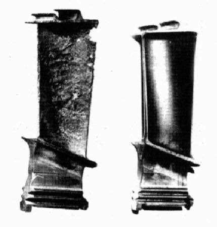
With today's jet engine operating temperatures, thermal barrier coating failure results in melting of the blade. But even without reaching such catastrophic failure, blades suffer from accelerated oxidation and, depending on the environment, hot corrosion. Coatings can considerably enhance the oxidation/hot corrosion resistance of these components, as illustrated below:
The result of 2500 h low altitude sea flight service on an uncoated and NiAl coated blade turbine blade, from Eskner, 2004.
Oxidation is the reaction between the coating (or in its absence, base alloy) with the oxidants present in the hot gases. Hot corrosion occurs from surface reactions with salts deposited from the vapour phase.
As discussed in the next section, different service conditions result in different degradation mechanisms being predominant. In addition to oxidation and hot corrosion, coatings will evolve through diffusion with the substrate alloy, as they are not in thermodynamic equilibrium with the latter. This is of concern, not only because it may modify the carefully designed mechanical properties of the substrate, but also because loss of Al to the substrate reduces the oxidation life of the coating.
Bibliography
Eskner M., PhD thesis, Royal Institute of Technology, Stockholm, 2004.
Coatings
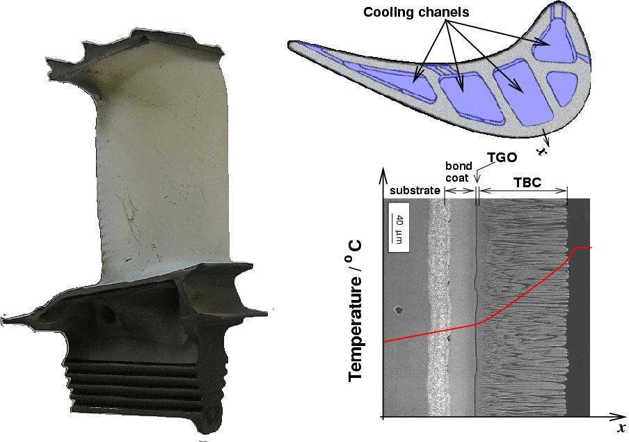
Typical coatings for high-temperature applications involve an oxidation resistant coating and a thermal barrier coating (TBC). The oxidation resistant coating is also called a bond coat because it provides a layer on which the ceramic TBC can adhere.
In many papers, TBC is used to refer to the ensemble bond coat + TBC; in the following, I will use TBC only to refer to the ceramic thermal barrier.
Illustration of a typical coating system in a high-pressure turbine blade. Clockwise, a TBC coated high-pressure turbine blade, view from top showing the cooling systems (image courtesy Rolls-Royce Plc), and schematic profile temperature, note the drop of temperature close to the blade surface due to the presence of a thin cooling air film (SEM picture courtesy M. Pusch).
As noted in the introduction, the TBC is oxygen transparent and therefore does not provide any oxidation resistance.
Note: the following will make extensive use of these abbreviations:
TGO: thermally grown oxide
TBC: thermal barrier coating
APS: air plasma spray
LPPS: low pressure plasma spray
EBPVD: electron beam physical vapour deposition
Bibliography
Padture et al., Science, 296:2002, 280-284, 'Thermal barrier coatings for gas-turbine engine applications'.
Bond coats: introduction
The following table compares the severity of the different surface-related problems for gas turbine applications:
Application
Oxidation
Hot corrosion
Interdiffusion
Thermal fatigue
Aircraft engines
Severe
Moderate
Severe
Severe
Land-based power generation
Moderate
Severe
Moderate
Light
Marine engines
Moderate
Severe
Light
Moderate
Comparison of problems for gas turbine applications, after F.S. Pettit and G. W. Goward, Coatings for High Temperature Applications, Applied Science Publishers, 1983.
Recent generations of superalloys for single crystal turbine blades contain relatively high percentages of refractory elements such as Ta, W or Re which enhance the high-temperature mechanical properties (Chen, 1997).
This, however, is done at the expense of Cr and Al. Given the severe environmental conditions in which the blades operate, the removal of these elements (beneficial for oxidation resistance) implies even greater degradation problems.
To palliate for this lack of appropriate oxidation/corrosion resistance, an external coating is applied to the blades. Its purpose is to allow for the growth of a resistant oxide layer. Of all possible oxides, α-Al2O3 offers excellent protection and very low growth rates (in a minority of cases, Cr oxides are preferred). The composition of the coating must therefore be chosen carefully so as to ensure growth of α-Al2O3.
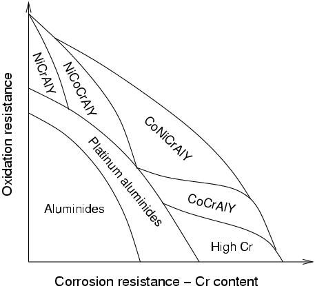
Optimum coating composition in relation to oxidation and hot-corrosion resistance, after M. Schütze, Corrosion and Environmental Degradation Vol. II, Wiley-VCH, 2000.
The two most widely used types of coatings are aluminides (NiAl or Ni2Al3) and MCrAlY coatings (where M is Fe, Co and/or Ni). The former are obtained by surface enrichment by diffusion, the latter by plasma spray or EBPVD. An additional ceramic coating is often applied to high-temperature components (TBC). In this context, the oxidation resistant coatings also provide a 'transition' layer on which the TBC adheres better than on the substrate. For this reason, the oxidation resistant layer is also referred to as a bond coat.
When the Al content of the coating is too low, other oxides than α-Al2O3 may form, the nature of which depends on the exact composition of the coating. For reasons which will be explained later on, this can result in failure and is therefore to be avoided.
Blade integrity is now critically dependent on these coatings and additional ceramic thermal barrier coatings. Unfortunately, 'prime-reliability', the concept of a coating whose life no longer conditions that of the blade, has not been achieved yet. With the increasing cost of the blades themselves, the practice of coating renewal has developed. In this operation, a gas turbine is taken apart, each blade is dismantled, its surface cleaned and a new coating applied.
With, on one hand, the prospect of coating failure leading to catastrophic blade loss, and on the other hand an extremely expensive maintenance process, it is no surprise that much research is dedicated to improving the evaluation of remnant life.
Bibliography
Chen J. H. et al., Surf. Coat. Techn., 92:1997, 69-77, 'Degradation of the platinum aluminide coating on CMSX4 at 1100 °C'.
M. Schütze ed., Corrosion and Environmental Degradation Vol. II, Wiley-VCH, London, in Materials Science and Technology series.
Bond coats: aluminides
In modern applications involving very high temperatures or severe hot corrosion problems, aluminide coatings provide relatively limited protection. They are nevertheless still widely used in less demanding applications.
Constitution
Diffusion aluminide coatings are based on the intermetallic compound β-NiAl. Although different processes exist to form them, pack cementation is the most widely used as it is inexpensive and well adapted to coating of small parts.
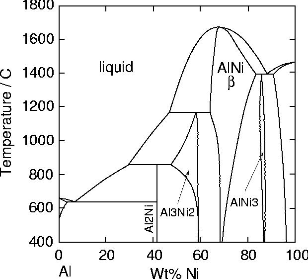
The Al-Ni phase diagram.
Pack cementation falls in the category of chemical vapour deposition. In this process, the components to be coated are immersed in a powder mixture containing Al2O3 and aluminium particles. About 1–2 wt% of ammonium halide activators are added to this 'pack'. This is then heated to temperatures around 800–1000 °C in an argon or H2 atmosphere. At these temperatures, aluminium halides form which diffuse through the pack and react on the substrate to deposit Al metal.
The activity of Al maintained at the surface of the substrate defines two categories of deposition methods: low and high activity, also referred to as outward and inward diffusion respectively.
In cements with low aluminium contents (low activity/outward), the formation of the coating occurs mainly by Ni diffusion, and results in the direct formation of a nickel-rich NiAl layer. The process requires high temperatures (1000–1100 °C). In service, the interdiffusion with the substrate is very limited and the gradient of Al in β is low.
In cements with high aluminium contents (high activity/inward), the coating forms mainly by inward diffusion of aluminium and results in the formation of Ni2Al3 and possibly β-NiAl. Aluminising temperatures can be lower (700–950 °C). There can be a high Al concentration gradient in the coating, and also significant interdiffusion with the substrate during service. For these reasons, a diffusion heat treatment is generally given at 1050–1100 °C to obtain a fully β layer.
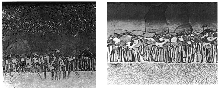
Microstructures of two types of aluminide coatings on superalloys. Left: high activity/inward diffusion; right: low activity/outward diffusion. From M. Eskner, PhD thesis, Royal Institute of Technology.
The structure and composition of the coating depends on the substrate, implying that coatings must be tailored for a given alloy. Aluminide coatings lack ductility below 750 °C. One of the major problems faced by aluminide coatings is thermomechanical fatigue, as cyclic strains induced by temperature gradients in the blades can lead to thermal fatigue cracks.
Influence of substrate
The substrate composition strongly influences the final microstructure of the system, in a manner which also depends on the process.
In low activity/outward diffusion coatings, the alloying elements present in the substrate will also tend to diffuse into the coating layer, to an extent limited by their solubility. In high activity/inward diffusion coatings, they enter in solution the compound layer in formation, or as precipitates potentially forming during the treatment.
Of the elements present in the alloy, titanium is thought to be particularly detrimental to the oxidation resistance of such coatings, as it leads to the formation of TiO2 crystals which break the alumina layer.
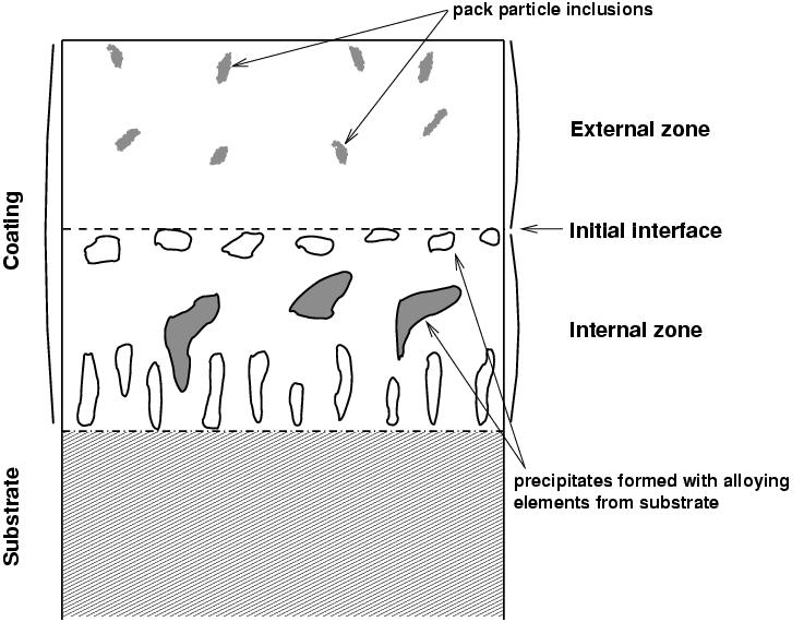
A typical microstructure of a low activity aluminide coating is illustrated below. The external zone is typically Al-rich β-NiAl, while the internal one is Ni-rich.
Schematic illustration of aluminide coating obtained by low activity pack cementation. After R. Pichoir, 1978.
Further reading
R. Pichoir, 'Aluminide coatings on nickel or cobalt-base superalloys', in High Temperature Alloys for Gas Turbines, Applied Science Publishers, 1978.
Metallic and Ceramic Coatings, Production, High Temperature Properties and Applications, M.G. Hocking et al., Longman Scientific and Technical.
Cocking J. L. et al., Surf. Sci. Techn., 36:1988, 37-47.
Sivakumar R. et al., Surf. Sci. Techn., 37:1989, 139-160, 'High temperature coatings for gas turbine blades: a review'.
Bond coats: Pt-aluminides
NiAl coatings tend to suffer strongly from interdiffusion with the substrate, which results in the formation of γ' at the expense of β.
The idea of introducing a diffusion barrier led to the invention of Pt-aluminide coatings, which are obtained by similar methods as conventional aluminides, but after electroplating the blade with Pt. The layer of Pt deposited is typically 5–10 μm (Schütze, 2000).
Because the plating can increase the life of the blades by up to three times (Sivakumar, 1989), the cost of Pt plating is easily compensated.
Interestingly, it was found that Pt additions not only did not provide a diffusion barrier, but also enhanced Al diffusion (Chen, 1997). When applied on the second-generation superalloy CMSX4, Pt formed TCP (topologically close-packed) phases with some elements of the substrate (Re, W, Mo, Cr).
The exact reasons for the beneficial effect of Pt are not fully understood, but it was found that Pt improves oxide adherence and also contributes to better hot corrosion resistance.
Pt appears to partially substitute Ni in β-NiAl, and also to form PtAl2 which is believed to act as an Al reservoir. It has also been proposed that Pt acts in a similar manner as Y in MCrAlY coatings. In these coatings, Y combines with S; this greatly increases the coating life as S is otherwise detrimental to the adherence of the oxide layer. There is nevertheless no evidence of a similar effect of Pt in β-NiAl coatings (Evans, 2001).
Further reading
Evans A. G. et al., Prog. Mater. Sci., 46:2001, 505-553, 'Mechanisms controlling the durability of thermal barrier coatings'.
Chen J. H. et al., Surf. Coat. Techn., 92:1997, 69-77.
Bond coats: MCrAlY
Introduction
As discussed in previous sections, aluminide coatings strongly interact with the substrates and must therefore be tailored for each different alloy.
Overlay coatings, as opposed to diffusion coatings, provide more independence from the substrate alloy, but also more flexibility in design as compositions can be modified depending on the degradation mechanisms expected to prevail.
Typical MCrAlY bond coats (where M is Fe, Co or Ni) contain at least 4 elements, which means that coating methods such as pack cementation are considerably more difficult to use, as the activity of each element in the pack would have to be controlled carefully so as to obtain a coating of the required composition.
The presence of a significant amount of Cr gives these coatings excellent corrosion resistance combined with good oxidation resistance.
Alternative methods are therefore preferred, such as air plasma spray (APS), low pressure plasma spray (LPPS), or electron beam physical vapour deposition (EBPVD). Deposition is followed by a high-temperature heat treatment in a vacuum to allow interdiffusion and therefore improve adhesion (Richard, 1996).
Microstructure
MCrAlY coatings typically exhibit a two-phase microstructure (β + γ). The presence of γ increases the ductility of the coating, thereby improving thermal fatigue resistance.
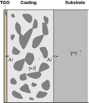
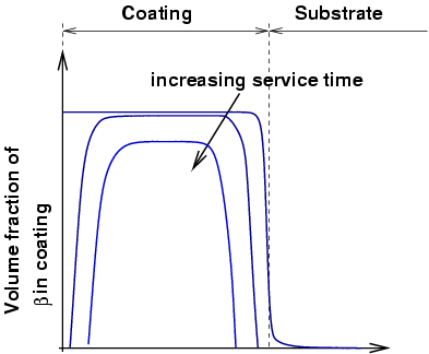
As for β-NiAl coatings, high temperature exposure results in depletion of the Al both to the TGO (thermally grown oxide) and to the substrate by interdiffusion. As the amount of Al decreases, the β phase tends to dissolve. For this reason, it is often described as an aluminium reservoir, and coating life is often measured in terms of the depletion of β.
Schematic illustration of MCrAlY microstructure.
Al diffusion to the oxide layer and the substrate results in depletion of beta from both sides.
Composition and role of additions
The M of MCrAlY stands for either Ni or Co, or a combination of both (when applied to steels, it can also be Fe), depending on the type of superalloy. Co-based coatings appear to have superior resistance to corrosion.
Cr provides hot corrosion resistance, but the amount that can be added is limited by the effect it is expected to have on the substrate, and the formation of Cr-rich phases in the coating.
Al content is typically around 10–12 wt%. Since oxidation life is essentially controlled by the availability of Al, it would be tempting to increase the aluminium content. However, this results in a significant reduction of ductility (Sivakumar, 1989).
MCrAlY also typically contains 1 wt% yttrium (Y), which enhances adherence of the oxide layer. It was initially thought that yttrium helped the formation of oxide pegs which anchored the oxide layer to the coating. However, it has been shown that there is little if any correlation (Smeggil, 1987), and it is now believed that the main role of Y is to combine with sulphur and prevent its segregation to the oxide layer, which is otherwise detrimental to its adhesion. Additions of hafnium (Hf) play a similar role.
The effect of other additions has also been investigated (Nicoll, 1982). It was found that silicon (Si) significantly improved cyclic oxidation resistance; however, it also decreases the melting point of the coating. 5 wt% is enough to lower the melting temperature to about 1140 °C. There is also evidence that it affects phase stability. For cyclic oxidation at 1000 °C, 2.5 wt% was found to be the optimum content.
Additions of rhenium (Re) have been shown to improve isothermal or cyclic oxidation resistance, and thermal cycle fatigue (Czech et al., 1994).
Additions of tantalum (Ta) can also increase the oxidation resistance.
Bibliography
Nicoll A. R. et al., Thin Solid Films, 95:1982, 21-34.
Smeggil J. L., Mater. Sci. Eng., 87:1987, 261-265.
Czech et al., Surf. Coat. Techn., 68:1994, 17-21.
Thermal barrier coatings
The role of thermal barrier coatings (TBC) is to provide thermal insulation of the blade. A coating of about 100–200 μm can reduce the metal temperature by up to 200 °C.
A TBC can be used either to:
Reduce the need for blade cooling (by about 36%), while maintaining an identical creep life of the substrate.
Increase considerably the creep life of the blade while maintaining the level of blade cooling.
The benefits of TBCs in terms of engine efficiency are comparable to those brought by the replacement of directionally solidified alloys for single crystal ones (Strangman, 1985).
Because they allow surface temperatures higher than the melting point of the substrate, ensuring the integrity of TBCs is critical. The failure is linked with large residual compression in the underlying thermally grown oxide (TGO), but details of the mechanism only begin to be understood (Evans et al., 2001).
TBC materials
For a ceramic coating to avoid spalling at the first thermal cycle, it is critical that its thermal expansion matches closely with that of the substrate. The coating must also exhibit a very low thermal conductivity.
For this purpose, yttria (Y2O3)-stabilised zirconia (ZrO2) (YSZ) is widely used. The addition of 5–15% yttria stabilises the zirconia in its high-temperature crystalline form, therefore avoiding phase transitions in the range of service temperatures.
Zirconia-based ceramics satisfy both requirements, with a thermal expansion coefficient of 11–13×10-6 K-1 and a thermal conductivity of about 2.3 W/(m·K) at 1000 °C for a fully dense material; this can be further reduced by introducing porosity (Evans, 2001).
The low thermal conductivity of YSZ is due to the presence of a high concentration of point defects which scatter lattice vibrations (Padture, 2002).
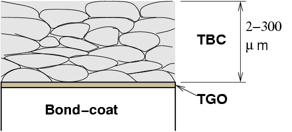
Schematic microstructure of a thermal barrier coating (TBC) obtained by air plasma spray (APS). The structure provides less strain resistance but is preferred for abradable seals.
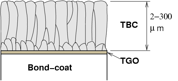
Schematic microstructure of a thermal barrier coating (TBC) obtained by electron beam physical vapour deposition (EBPVD). The columnar microstructure considerably enhances strain tolerance.
TBC coatings deposited by APS or LPPS offer a thermal conductivity significantly lower than that of a fully dense coating (0.9–1 W/(m·K)), as the boundaries and pores tend to lie parallel to the surface. By contrast, the thermal conductivity of EBPVD TBC is not as low (1.8–2 W/(m·K)), but EBPVD TBCs are preferred because of the strain tolerance imparted by the columnar microstructure.
In jet engine operating conditions, the lifetime of TBC coatings obtained by EBPVD has been reported to be between 8 and 13 times longer than equivalent systems where the TBC was deposited by plasma spray (Schulz, 2003). However, industrial experience indicates that this superiority is not maintained in land-based gas turbines, in which APS tends to give the best performances (Wells, 2004).
Deposition processes
Coating processes can be broadly divided into methods by which atoms attach individually to the surface (such as PVD or CVD), or methods which apply molten or semi-molten particles (thermal spraying).
Thermal spray methods
Thermal spraying consists of melting a consumable (powder or wire) and projecting it onto the substrate. Upon impact, the particles flatten and solidify rapidly. Adhesion is primarily mechanical. All thermal spraying processes are line-of-sight processes.
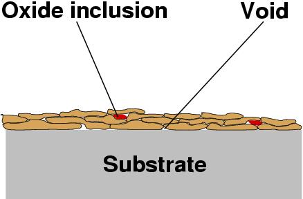
Schematic microstructure of a thermal spray coating, showing splat layers.
Flame spraying: Uses an oxyacetylene flame (about 2700 °C). Particle velocity is around 40 m/s, with a porosity of 10–15%.
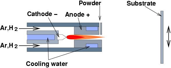
Plasma spraying: Uses an ionised gas plasma. The plasma temperature can exceed 16,000 °C, while particle velocity reaches 200–300 m/s. Porosity is reduced to 5–10%.
High velocity oxyfuel (HVOF): Uses oxygen and hydrogen with a fuel gas. Particle velocity ranges between 600–1000 m/s; porosity is reduced to 1–2%.
Schematic illustration of a plasma torch.
Electron beam physical vapour deposition
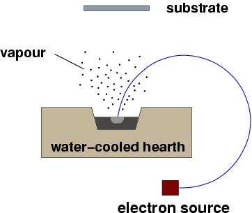
In EB-PVD, evaporation of a target ingot is obtained within a vacuum chamber using a focused electron beam. The vaporised atoms condense directly onto the line-of-sight surface of the substrate.
A simple EBPVD process schematic under vacuum conditions.
Practical use of coatings
HPT blades in jet engines mainly suffer from oxidation; Pt-aluminide coatings are preferred here. In power generation applications, the external surface of HPT blades typically receives an MCrAlY coating to combat the severe hot corrosion environment, while internal cooling channels are aluminised via non-line-of-sight pack cementation.
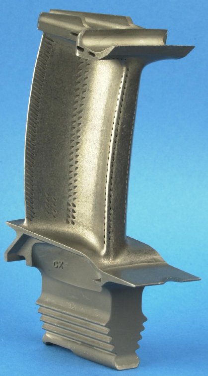
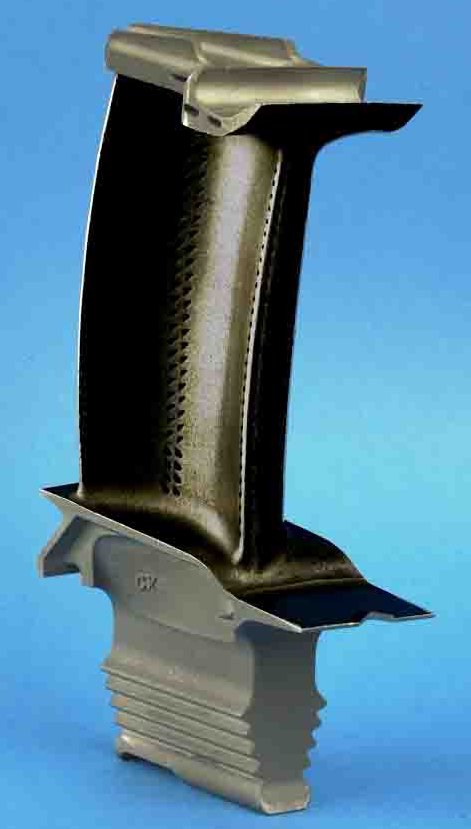
A jet engine HPT blade. Photo courtesy S. Tin, Rolls-Royce UTC.
Aluminised jet engine HPT blade. Photo courtesy S. Tin, Rolls-Royce UTC.
Low-cycle fatigue and thermomechanical fatigue of coated superalloys
Svjetlana Stekovic, Linköping University
The application of coatings to superalloys has mechanical side effects which can lead to premature failure via low-cycle fatigue (LCF) and thermo-mechanical fatigue (TMF). Mismatch in the thermal expansion coefficients, ductility, strength and elastic moduli between the coating and substrate can significantly reduce fatigue life.
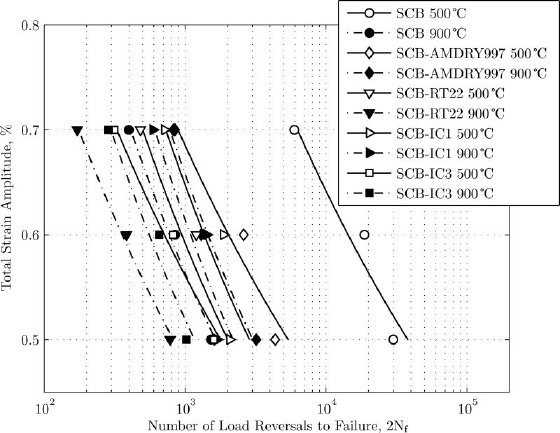
Tests were performed on three nickel-based superalloys (polycrystalline IN792, single-crystal CMSX-4, and SCB) under four coating configurations: AMDRY997 (NiCoCrAlYTa), RT22 (Pt-aluminide), and two innovative coatings with a NiW diffusion barrier (IC1 and IC3).
At 500 °C, all coatings had a detrimental effect on the LCF life due to brittle fatigue fracture of the coatings, which provided initial defects from which cracks propagated into the substrate.
Figure 1: LCF life trend data for single-crystal blade (SCB) superalloy.
At 900 °C, the fatigue lives of most coated specimens were longer due to improved coating ductility above the ductile-to-brittle transition temperature (DBTT). The exception was RT22 on SCB; because of the low ductility of its β-NiAl phase, it cracked prematurely under a 1.2% strain amplitude.
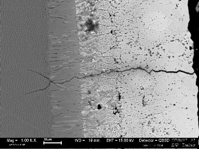
Figure 2: RT22 on single-crystal substrate tested at 500 °C.
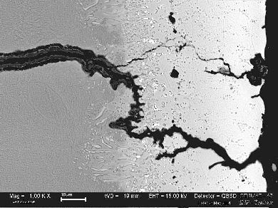
Figure 3: RT22 on single-crystal substrate tested at 900 °C.
The out-of-phase (OP) TMF life of the coated specimens was uniformly shorter than that of the uncoated references. Cracks developed through the formation of surface macro-cracks during the tensile cycle at the lower temperature extreme of the TMF loop.
Figure 4: CMSX4 alloy with IC1 coating under TMF loading.
Figure 5: Crack initiation accelerated by localized oxidation at the RT22 coating-substrate interface.
An alloy developed for high-temperature service where severe mechanical stress and surface oxidation resistance are required; typically based on nickel, cobalt or iron.
Bond coat
An oxidation-resistant metallic interlayer (e.g., MCrAlY or aluminide) applied between a superalloy substrate and a thermal barrier ceramic coating to enhance adhesion.
Thermal barrier coating (TBC)
A low thermal conductivity ceramic layer, typically yttria-stabilised zirconia, applied to high-temperature components to insulate the underlying metal.
Thermally grown oxide (TGO)
A thin oxide layer (primarily α-Al2O3) that forms naturally between the bond coat and the TBC during high-temperature service.
Pack cementation
An in-situ chemical vapour deposition process where a component is heated within a sealed powder mixture to enrich its surface with elements like Al or Cr.
DBTT
Ductile-to-brittle transition temperature; the temperature range over which a material changes from a ductile manner of fracture to a brittle manner.

 Video guide