
Steels for Bearings
Progress in Materials Science 57 (2012) 268-435
Director, SKF University Technology Centre for Steels
Tata Steel Professor of Metallurgy
University of Cambridge
Professor of Computational Metallurgy
Graduate Institute for Ferrous Technology
Pohang University of Science and Technology
- Download major review
Study guide Audio podcast

- Soft white-etching matter
- Elimination of white-etching matter
- Adiabatic shear?
- Duplex Hardening: Aeroengine Bearings
- Cracking bearings
- Superbainite bearings?
- White matter in bearings
- Mechanical bearings
- Images of new rolling contact fatigue machine
- Cementite dissolution in 52100 steel
- Spheroidisation of Bearing Steels
- Severe tempering
- Special issue
- Video lectures
- Chocolate bearings
- Plastic bearing
- Gigacycle samples
- Isotropic steels
- Hydrogen trapped in bearing cracks
- Bearing steel microstructures after aircraft gas turbine engine service
- Behaviour of aircraft bearing steels under rolling contact loading
- Evolution of white-etching cracks
Abstract: A casual metallurgist might be forgiven for believing that there are but a few basic types of steels used in the manufacture of some of the most technologically important engineering components, the rolling bearings. First the famous 1C-1.5Cr steel from which the majority of bearings are made. Its structure is apparently well-understood and the focus is on purity in order to avoid inclusions which initiate fatigue during rolling contact. Then there is the M50 steel and its variants, from which bearings which serve at slightly higher temperatures in aeroengines are manufactured, based on secondary-hardened martensite.
The casual metallurgist would be wrong; there is a richness in the subject which inspires deep study. There are phenomena which are little understood, apparently incommensurate observations, some significant developments and other areas where convincing conclusions are difficult to reach. The subject seemed ready for a critical assessment; hence, this review. The structure and properties of bearing steels prior to the point of service are first assessed and described in the context of steelmaking, manufacturing and engineering requirements. This is followed by a thorough critique of the damage mechanisms that operate during service and in accelerated tests.
Introduction
The Oxford English Dictionary defines a bearing "as a part of a machine that allows one part to rotate or move in contact with another part with as little friction as possible". Additional functions include the transmission of loads and enabling the accurate location of components. A bearing may have to sustain severe static as well as cyclic loads while serving reliably in difficult environments. Steels are well-suited in this context, and in their many forms, represent the material of choice in the manufacture of bearings. There has been more than a century of work on alloys for rolling bearings; an elegant summary of the advances in steel and processing technologies that led to the contemporary state of affairs has been given by Zaretsky [1, 2]. And yet, a cursory glance at the literature reveals that the subject remains fascinating, with many unresolved issues, disparate observations and a need for radical innovations to deal with the modern requirements of large rotating components serving in somewhat unpredictable environments.
Bearings consist of rolling elements (balls, cylinders or barrel shapes) and rings which form the raceways. The manufacturing process for the rolling elements involves the high reduction-rate plastic deformation of raw, cast material, into billets with square sections. The deformation helps to break up the cast structure and to close porosity. The billets are then reduced in section by further rolling or drawing, heat-treated to a softened state and cut into lengths suitable for the manufacture of balls; the finished rolling elements are then quenched and tempered, or isothermally transformed, to the required hardness. Bearing rings can be made from seamless tube produced by hot-rolling and similarly hardened, followed by careful machining and grinding to the final dimensions and surface finish. The vast majority of rolling elements and raceways are made using steel.
This review is an exploration of the nature of bearing steels and their performance during service, based entirely on openly available published literature. The focus is on metallurgy but it has been necessary to cover aspects of engineering in order to present a coherent picture. I have attempted to cover the widest possible range of alloys but it is inevitable that the greatest attention is paid to those which are most versatile, most used and deeply researched.
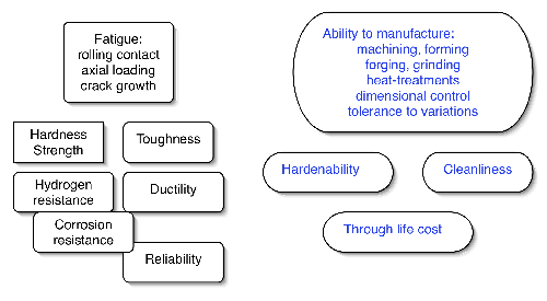
It is worth emphasising at the outset that the demands made on any candidate bearing alloy go well beyond considerations of final structure and mechanical properties. The ability of the material to cope with each step in the sequence of manufacturing processes is seminal to its success or failure; a conservative list of the requirements is presented in Fig. 1. Of the very many alloys that have been investigated in the history of bearing steels, there are only two categories of steels which find application in the majority of bearings; those which are hardened throughout their sections into a martensitic or bainitic condition, and others which have soft cores but tenacious surface layers introduced using processes such as case or induction hardening. We shall see that within these categories, there is a just a handful of alloys which dominate the market for the simple reason that they best meet all of the manufacturing and engineering requirements. A great deal of the initial part of this section will focus on steels which are tempered or transformed at temperatures less than 300°C and which contain low concentrations of substitutional solutes when compared with the specialised alloys which are described later. The latter include secondary-hardening steels for bearings designed to operate at elevated temperatures or others which are designed to resist corrosion.
Types of Bearings
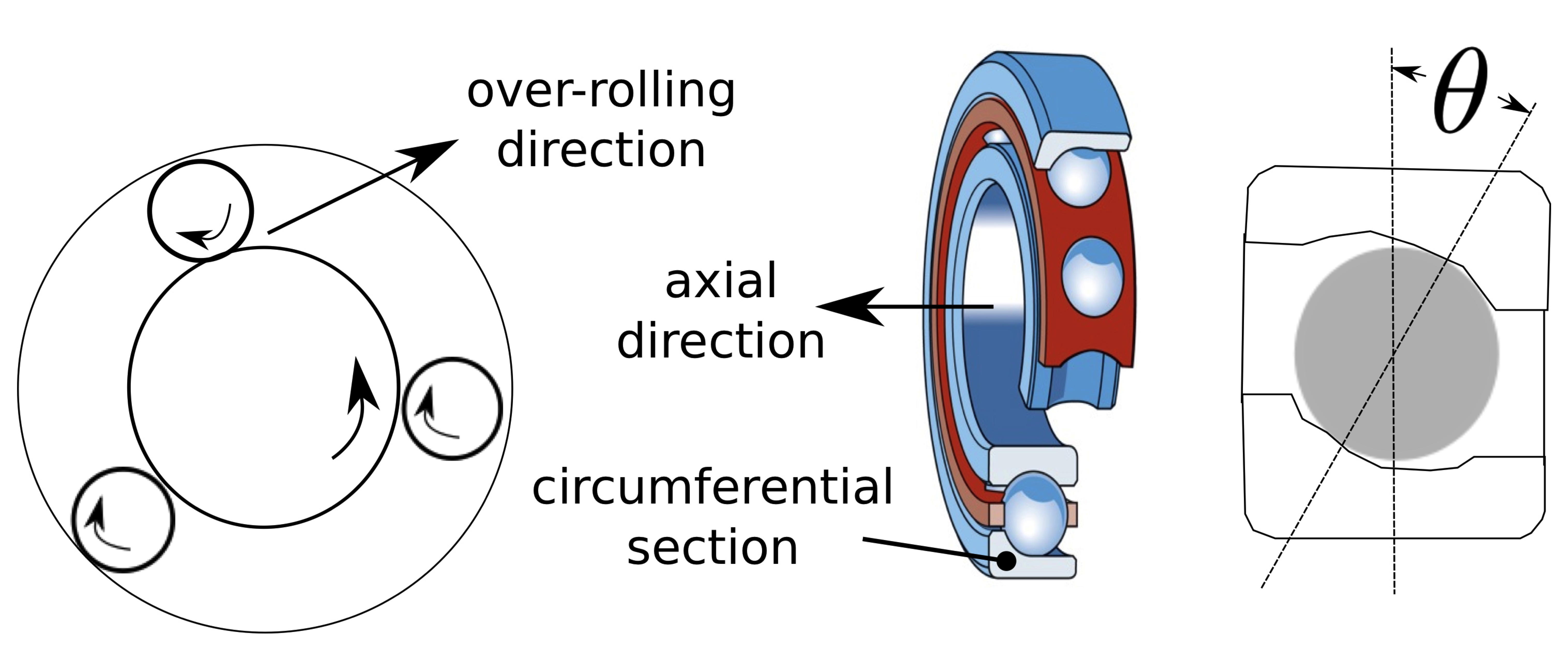
The purpose of this section is not to give a comprehensive description of the vast variety of bearing geometries, but rather to establish the basic terminology which is used in experimental investigations. Much more detail including images of specific bearing configurations can be found elsewhere [4]. Aspects of geometry can dramatically influence the choice of material, bearing performance and its ability to bear loads. For example, the contact angle defined in Fig. 2 influences fatigue life and the temperatures developed during bearing operation [5].
Spherical balls enclosed between two concentric rings permit the rings to rotate relative to each other, whilst supporting a radial load; this is the essence of a ball bearing. Roller bearings use cylinders instead of balls and have a greater load bearing capacity because of the greater contact between the rolling element and the rings. Cylindrical roller bearings played a seminal role in the development of the continuous rolling mill, now used in the manufacture of billions of tonnes of wide-strip steel [6]. Prior to this, the rolling process was by repeatedly passing the steel through a single mill, involving many steps of handling and heating. The original bearing design had an outer forged steel ring and a fixed bronze-bearing race holding steel rollers in position. Modern bearings of this kind would be made entirely of steel although there may be retaining cages which are made from other materials. In spherical roller bearings, the rolling elements are barrel-shaped with two parallel raceways permitting angular contact; the double set permits the bearing to accommodate shaft misalignment.
Taper roller bearings take this concept further by making the rings and rollers tapered, to increase the contact area, permitting large radial and thrust loads. They are for this reason used in some helicopter transmissions to take advantage of their greater load capacity for a given shape or weight when compared with ball or cylindrical roller bearings [7].
In needle roller bearings, the cylinders are long and thin, so that the outer diameter of the bearing is not much greater than that of the inner ring. This makes for a compact design which can be an advantage when space is at a premium. A spherical-roller bearing uses barrelled cylinders as the rolling elements, with two sets of rollers enclosed by the rings. This allows the bearing to accommodate a misaligned load.
Some terminology needed to define directions, and which is used throughout this review, is defined in Fig. 2.
Lean Steels: Microstructure
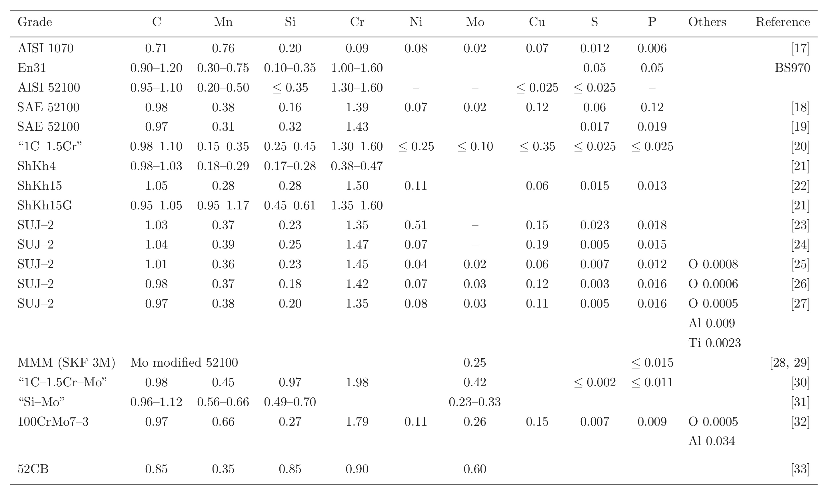
Steels with carbon concentrations in the range 0.8–1.1 wt% and the total substitutional solute content less than 3 wt%, designed originally for machining tools, have historically dominated the mass market for bearings [10, 9]. They can be made martensitic by quenching in oil or salt, from a temperature where the material is mostly austenite. However, the focus of this section is on the 1C-1.5Cr type alloys which are extremely popular. Ball bearing tests conducted in 1901 by Stribeck indicated its suitability for the application [11] and was apparently adopted some 120 years ago for bearings by Fichtel & Sachs of Schweinfurt in 1905, and has persisted to this day as a key alloy in the manufacture of bearings [10, 12], with progressive improvements in fatigue performance achieved primarily by improvements in cleanliness with respect to non-metallic inclusions. It represents the majority of the six million tonnes of bearing steel manufactured per annum. The alloy is referred to by numerous national and international designations as indicated in the caption to Table 1; all of these for convenience will henceforth be referred to using the single designation, 52100 type steel, in the present review.
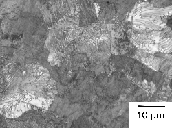
It is usual for the steel to be supplied in a hot-rolled condition with a pearlitic microstructure including some proeutectoid cementite at the prior austenite grain boundaries, Fig. 3a. The proeutectoid cementite, when it forms networks at the austenite grain boundaries, is undesirable because it has been shown to adversely affect the rolling contact fatigue life in accelerated tests conducted with contact stresses in excess of 5 GPa [13]. The networks can be minimised by sufficiently rapid cooling from the final hot-deformation temperature [14], or by annealing to spheroidise the cementite [15], Fig. 3b. As will be discussed later, the relatively large carbon concentration of the steel speeds up the spheroidisation process and is one of the reasons for the success of the steel, that it can be soft annealed with relative ease. The metallurgy of the spheroidisation process is detailed in section 7. After the appropriate machining or forming, the components are subjected to hardening heat treatments described next.
 (b)
(b) 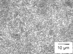
52100 Steel: Equilibrium and Austenitisation
The calculated equilibrium phase fractions for the mean composition listed as 1C-1.5Cr in Table 1, as a function of temperature, are illustrated in Fig. 4. This is representative of some of the most widely used bearing steels. The calculated [41] equilibrium compositions of austenite and cementite at a typical austenitisation temperature of 840°C are listed below. An isothermal transformation diagram for austenitisation is shown in Fig. 5 [42]. Although the steel becomes fully austenitic at temperatures in excess of about 900°C, this is under equilibrium conditions but austenitisation at 1040°C for 20 min is found in practice to completely dissolve the cementite in 52100 steels containing as much as 1.1 wt% carbon [43]; such a heat treatment results in an austenite grain size of between 40–60 µm1. The importance of controlling the austenite grain size to avoid the cracking of martensite plates is discussed in section 6.
 |
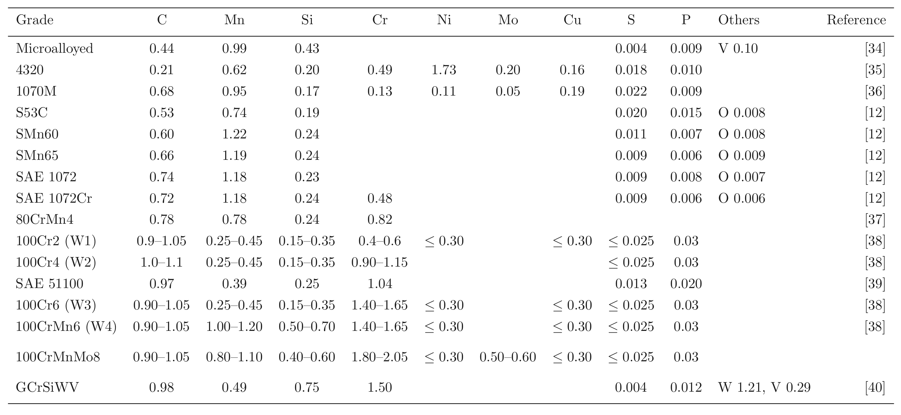 |
Fig. 6 shows how the austenite grain size varies with the austenitisation temperature, with a large increase when carbides are taken into solution at the highest of temperatures. The aluminium has an influence via aluminium nitrides, but only when the austenitisation is conducted in the single γ-phase field. Even finer grain sizes can be achieved by rapid heat treatment [45]; although these particular experiments were conducted using molten metal baths, short-duration austenitisation is a reality in commercial induction hardening processing.
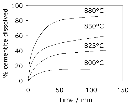
The kinetics of the cementite dissolution process can be represented by a semi-empirical time-temperature parameter based on Avrami theory [46]. The carbide dissolution process can be accelerated by cold working the steel prior to austenitisation [44]. Because equilibrium is not achieved in commercial heat treatments, there is a degree of superheating necessary in order to induce the formation of austenite; during heating at 2°Cs-1, the austenite begins to form at Ac1 = 756°C and ferrite is eliminated when 790°C is reached [44].
About 3–4 wt% of cementite typically is undissolved at 840°C, the exact quantity depending on the austenitisation time and the starting microstructure; the cementite in the final microstructure helps improve the resistance of the steel to wear [49]. The cementite also absorbs some of the chromium in the steel, although the level of substitutional solute may not reach that indicated by equilibrium within the time periods involved in industrial processing [50]. Fig. 7 shows how the chromium concentration varies with time and temperature; the cementite initially forms rapidly with a composition which is depleted in substitutional solutes and then equilibrates over time [52, 51], as is widely observed in steels for the energy industries [53]. Chromium also raises the ACM temperature so the fraction of cementite is greater relative to a chromium-free steel, at any given temperature within the γ+θ phase field [54]. The thermodynamic stability of the cementite is enhanced by enrichment with chromium so that the undissolved particles are able to resist change during heat-treatment and processing [52, 55]. Recent work using X-ray and electron diffraction has indicated that some of the spherical particles assumed to be cementite may in fact be (Fe,Cr)23C6 [56]; the particles were not chemically analysed but their chromium concentrations should be much higher than have been reported in Fig. 7. One difficulty is that (Fe,Cr)23C6 is not a stable phase at the austenitisation temperature used (845°C), as can be seen in Fig. 4; the discrepancy may be related therefore to chemical segregation in the material and further work is needed where the volume fraction of the chromium-rich carbide can be measured.
The austenitisation time is typically 20 min so it is an approximation to assume that equilibrium is reached within this time period; the measured kinetics of dissolution are illustrated in Fig. 8. The austenite also becomes depleted in carbon (0.86 wt%), giving a calculated martensite-start temperature [57, 58] of 148°C. Subsequent transformations therefore occur from this depleted austenite which has a lower hardenability.
52100 Steel: Quenching & Tempering
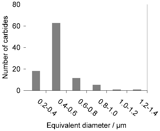
Quenching from the austenitisation temperature leads to a microstructure containing martensite, about 6 vol% of retained austenite [60, 12] and approximately 3–4% of cementite particles which failed to dissolve during austenitisation. These particles are normally uniformly distributed and have a size of about 0.4–0.6 µm (Fig. 9). The steel is then tempered at approximately 160°C, a process which may lead to the decomposition of a proportion of retained austenite, and to the precipitation of a variety of transition carbides of iron from the supersaturated martensite. These carbides include η [61] and χ [62]. Following the low-temperature tempering treatment, the martensite relies on carbon in solid solution and on fine transition carbides of iron, predominantly ε-carbide (Fig. 10, [63]) for its strength. The material therefore softens during prolonged service at temperatures in excess of about 200°C, which as a consequence is the limit of its maximum service temperature [64]. The bearing is sometimes heated between 80–100°C in order to interference-fit it on to a shaft; short-term excursions to 225°C using induction heating have been found to avoid softening even when the steel itself was tempered at 150°C after martensitic transformation [65]. Work has also been reported on induction tempering, where a 40s excursion to 230°C is in terms of hardness found to be equivalent to a 1h heat treatment at 150°C [66].

Attempts have been made to reduce the amount of undissolved cementite by decreasing the carbon concentration to 0.77 wt% and maintaining the hardness by solid solution strengthening with silicon and manganese [67]2. Although the steel concerned gave comparable fatigue properties in accelerated tests, the industry has persisted with alloys containing some 1 wt% of carbon. One reason is that lower carbon steels are slower to spheroidise [69] and the manufacturing process for bearings requires the steel to be in a soft-annealed condition for certain machining operations. A larger than normal concentration of silicon (0.85 wt%) has also been used in a modified 52100 steel microalloyed with vanadium, with the purpose of reducing the chromium concentration whilst maintaining the hardness and hardenability [71, 70], and a similar approach involving the use of silicon and molybdenum ("Si-Mo", Table 1) [31, 73, 72]. Silicon, by virtue of its low solubility in cementite, retards the low-temperature tempering of martensite [78, 74, 76, 75, 77], and molybdenum through the formation of alloy carbides or their precursors, helps improve the hot-hardness so long as the tempering treatment used permits substitutional solutes to be mobile. The increase in temper-resistance of silicon-enhanced (0.31–1.42 wt%) 52100 steel is said to lead to increased rolling contact resistance, presumably because of the greater hardness for the same level of heat-treatment [79]. Nevertheless, in general the 52100 type alloys reign supreme and substitutes simply do not seem to have been adopted on a comparable scale, presumably because the full set of data necessary for implementation into industrial practice is not available for many of the modified alloys.
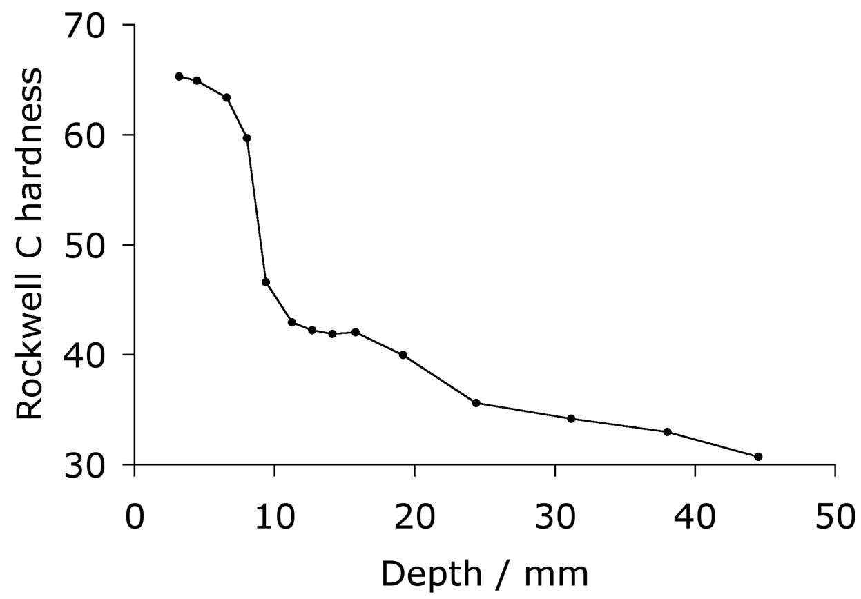
The hardenability of the alloy is illustrated in the Jominy curve plotted in Fig. 11, which shows that a depth of at least 5 mm can become fully martensitic; the actual hardenability can vary significantly depending on the exact chemical composition within the specification range. The virgin martensite in 52100 with its large carbon concentration is so supersaturated with carbon, that the driving force for precipitation is also large; this is why the hardness of the steel is somewhat sensitive to the quench rate because autotempering of the martensite occurs as it forms at the slower rates [80, 81].
 (b)
(b) 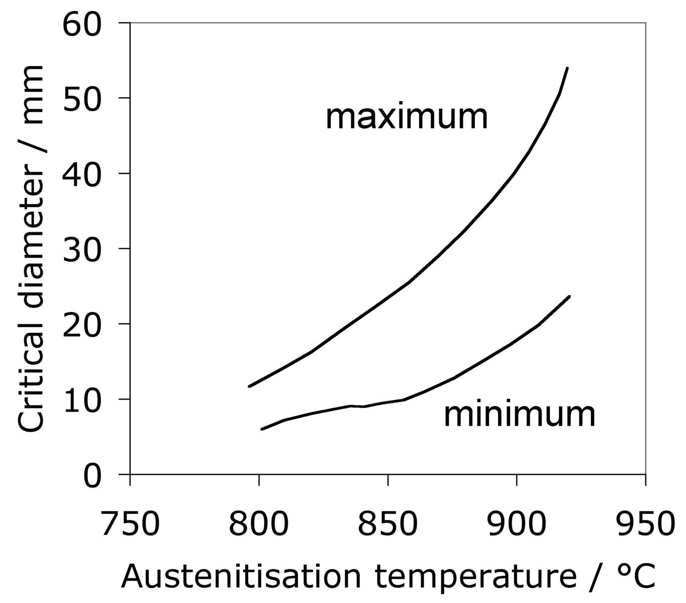
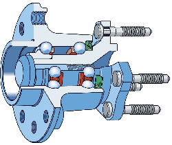
The lower carbon alloy S53C (SAE1053) is used in the manufacture of the rings which form the bearing race for the rolling elements in wheel hub-bearings for automobiles and trucks, Fig. 12. The alloy is cheaper because there is no deliberate addition of chromium and hence also does not require homogenisation after casting. The race surfaces are induction hardened to 59 HRC (Rockwell C hardness) in order to cope with the rigours of rolling contact loads; the contact fatigue life without this hardening is about a third that of the 52100 type steel because the lower carbon content reduces the hardness of the martensite [12]. Another variant of the steel is microalloyed with 0.1 wt% vanadium to improve its strength and toughness in the forged condition. A higher general strength can help reduce the mass of steel required to sustain the design loads [87]. Alloy 1072 is also widely used in the surface induction-hardened condition for hub bearing races, and because of its greater carbon and manganese concentration (Table 1) has a somewhat greater hardenability that S53C.
 (b)
(b) 
52100 Steel: Bainite
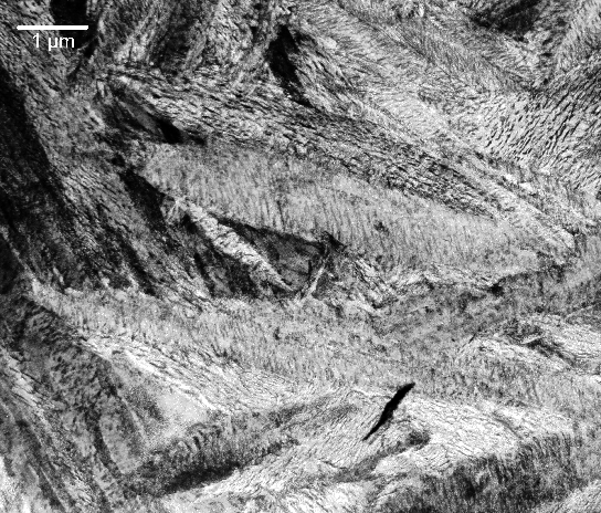
The 52100 type steels (Table 1) can be made bainitic by isothermal transformation in the temperature range 200–450°C, with lower bainite dominating the microstructure when the transformation temperature is less than 350°C [20]. The carbide in the lower bainite is cementite [19], which is in contrast to tempered martensite where it is ε-carbide [90, 63]3. The difference arises because there are two demands on the initial excess carbon dissolved in the bainitic ferrite, i.e., partitioning into the residual austenite and precipitation. When the former dominates, the precipitation is predominantly from carbon-enriched austenite [93]. The lower bainitic microstructure observed in 52100 following isothermal transformation at 230°C is illustrated in Fig. 13, [94].
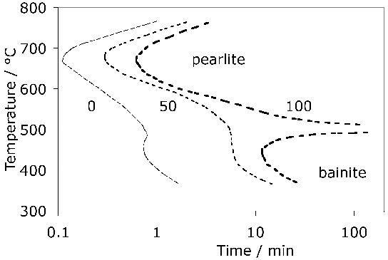
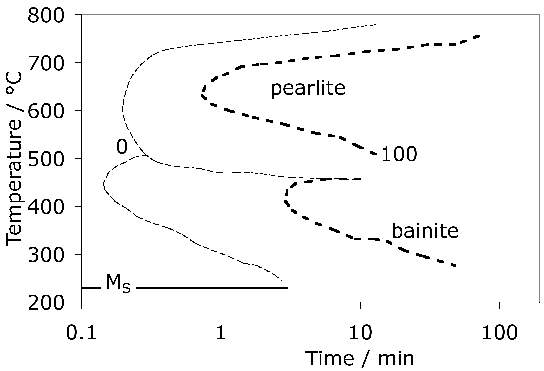
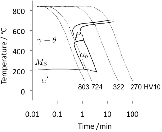
A measured time-temperature transformation diagram for 52100 steel is illustrated in Fig. 144. Fig. 15 shows an alternative diagram, plotted on the same horizontal scale for an almost identical steel which has been austenitised at a lower temperature so that the carbon concentration in the austenite would be reduced; the consequent increase in driving force for transformation leads to an acceleration of the bainite reaction [95]. On the other hand, the formation of pearlite is faster when the austenitisation temperature is greater (cf. Figs 14 & 15) because of the larger concentration of carbon dissolved in the austenite. A continuous cooling transformation diagram is shown in Fig. 16, illustrating the change in MS when martensite is preceded by partial transformation to bainite, due to the enrichment of the residual austenite with partitioned carbon.
The complete transformation to bainite at a temperature just above MS (i.e., approximately 230°C) can take some 4 h, which adds to the expense of heat-treatment when compared with the quenched and tempered condition5. It is possible to accelerate the reaction by first quenching to a temperature about 20°C below MS for less than a minute, and then raising it into the bainite range [94]. Step quenching of this kind, but within the bainite transformation range, has been known for some time to accelerate the transformation kinetics at the higher temperature [99, 100, 98, 97]. It has been demonstrated experimentally that the two-step treatment of bearing steel can shorten the heat-treatment time without sacrificing hardness [103, 101, 102, 94], but it remains to be proven that the process can be adapted to industrial practice. As an example, the complete transformation of 52100 steel at a constant 210°C takes 33 h, after which the hardness achieved is 60.1 HRC; by transforming the majority of the austenite at the same temperature but for 9 h, followed by heating to 250°C for 1 h, results in a completely bainitic microstructure with a slightly reduced hardness of 59.9 HRC [101].
It has been argued that a somewhat softer lower bainitic structure in the 52100 steel outperforms martensite when hydrogen embrittlement is an issue, because of its greater toughness and ductility [104]6. This is consistent with independent work on which the time at the austenitisation temperature was controlled to obtain different fractions of undissolved cementite; changing the fraction from 0.09 to 0.01 led to an increase in strength due to the greater carbon concentration in solution within the martensite, causing a deterioration in toughness and fatigue resistance [106]. On a similar rationale, pearlite and upper bainite are avoided since they apparently reduce fatigue life [20].
One advantage of a bainitic microstructure with its constituent carbides is that the reaction in bearing steels such as 52100 is able to progress until almost all of the austenite is consumed. It follows that the retained austenite content is minimal at about 1 vol.% [107] so that isothermally transformed structures of this kind are dimensionally stable. The heat treatments typical in the production of bainite also help minimise the possibility of quench cracking [107].
Relative Hardness of Rolling Element and Raceway
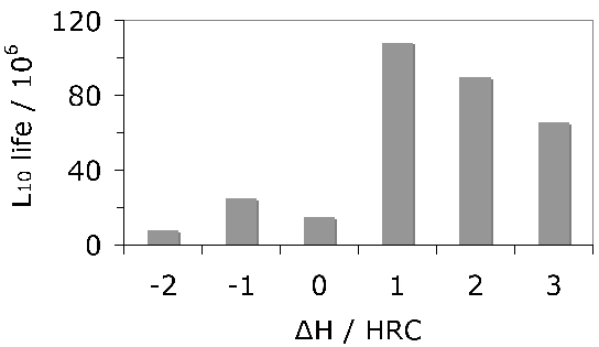
The same steel is often used for both the bearing raceway and the rolling elements. Early studies of how small differences in hardness of 52100 steel between the rolling element and the raceway influence the development of residual stress and sub-surface hardness during rolling contact have indicated an influence but not revealed systematic trends [111, 109, 110]. No correlation could be found between changes in hardness, the initial differential hardness and fatigue life. Furthermore, the physical mechanisms of such effects need to be clarified; the important point is that potential effects should be controlled in tests designed to measure stresses. More recent work [112] tends to suggest that rolling elements should be some 2 HRC harder in order to achieve the best rolling contact fatigue life, Fig. 17.
Impurities
The total concentration of an impurity, for example oxygen, does not necessarily determine the mechanical properties, but rather how the impurity is distributed in the steel. Thus, there is a dependence of rolling contact fatigue life against the length of strings of inclusions [113]. There are nevertheless correlations of fatigue performance against the total oxygen concentration [113, 115, 114] so it is valid to examine concentration as a parameter whilst bearing in mind that there will be noise in any interpretation based on total measures. Almost all the oxygen in solidified steel is present as oxides [117, 116] which are the key culprits in the processes which lead to the initiation of damage during repeated loading. This is why unlike many other technologies, the concentration of oxygen in modern bearing steels must be limited to less than 10 ppmw [118, 119], Table 2. The accuracy with which the concentration can be reproduced in practice is about ±1.5 ppmw [116] and there can exist a real range in the mean concentration within an ingot by some 2–5 ppmw [120]. The variance in oxygen measurements seems to become larger as the mean concentration increases [121].
| Steel Product | Maximum concentration / ppmw | ||
|---|---|---|---|
| Oxygen | Nitrogen | Hydrogen | |
| Automotive sheet | 30 | ||
| Drawn and ironed cans | 20 | 30 | |
| Line pipe | 30 | 50 | |
| Ball bearings | 10 | ||
| Tire cord | 15 | 40 | 2 |
| Heavy plate | 20 | 40 | 2 |
| Wire | 30 | 60 | |
Titanium is not a deliberate addition to the standard bearing steel (52100 type), but is present in small concentrations, typically 0.0025 wt%, primarily through the use of ferro-alloys (ferro-chromium in particular [117]) or from scrap [122] used in the steel manufacturing process. It may be introduced through the reduction of titanium oxide in the slag during basic oxygen steelmaking, especially when there is a substantial amount of aluminium dissolved in the melt [123, 124]. Titanium carbides and carbonitrides are known to initiate fatigue cracks in axially loaded or rotating-bending fatigue experiments (Fig. 79, [125]) and there is limited evidence in the context of rolling contact fatigue [126]. Indeed, it is said that Ti(C,N) particles of the same size and position as oxides do not induce the formation of butterflies [127]. This may be related either to the strength of the interface between the carbonitride and the matrix, or that the particles are more resistant to fracture and hence less effective in nucleating cracks which propagate into the matrix. The nitrogen concentration must be limited to < 10 ppmw in order to avoid titanium nitride formation [128].
Table 3 lists the lower limits in impurity concentrations said to be achievable in commercial reality. Although a practical limit to the total hydrogen content is probably about 1 ppmw, electron beam melted 52100 type steel has been shown to contain as little as 0.4 ppmw [22].
It has been speculated that interstitial nitrogen and nitrides can in the 52100 type bearing steels pin dislocations and hence reduce the ability to relax stresses, thereby leading to a reduction in the rolling contact fatigue life [129, 130]. Concentrations of total nitrogen are in the range 15–100 ppmw. Further work is needed to understand the mechanism since the correlations of properties against nitrogen content are based on the total concentration rather than that in solution [131]; some of the total may be tied up as nitrides. It is established that blowing liquid steel with nitrogen degrades the fatigue resistance and toughness of the 52100 type steels when compared with the use of argon for this purpose [132]. On the other hand, nitrogen concentrations up to 150 ppmw in M50 secondary hardening steel are not considered to be an important liability [133].
| Solute | P | C | S | N | H | O | Ti |
|---|---|---|---|---|---|---|---|
| Concentration / ppmw | 10 | 5 | 5 | 10 | < 1 | 3 | 10 |
The average total-hydrogen concentration of 52100 steel following manufacture into a bar with a diameter just over 15 mm can be as large as 8 ppmw. The concentration is not uniform but varies between 7–15 ppmw in the vicinity of the surface and diminishes to some 0.5–2.5 ppmw towards the core [135]. These are quite large concentrations which would normally be acceptable in the final bearing, so it is presumed that subsequent manufacturing processes lead to reductions in hydrogen concentration. The gaseous-impurity concentrations typically achieved during a variety of bearing-steel processes are listed in Table 4.
| Process | Hydrogen | Nitrogen | Oxygen |
|---|---|---|---|
| Air melting + vacuum degassing | 3.2 | 120 | 46 |
| Air melting | 4.8 | 150 | 67 |
| + 1 vacuum arc remelt | 1.8 | 80 | 37 |
| + 2 vacuum arc remelts | < 1 | 60 | 9 |
| + 3 vacuum arc remelts | < 1 | 50 | 5 |
| Vacuum induction melting | < 1 | 85 | 21 |
| Vacuum induction melting + vacuum arc remelting | < 1 | 60 | 6 |
Sulphur manifests within the steel in the form of compounds, particularly manganese sulphide. The sulphides can form in isolation or deposit on to existing oxide particles, with the fraction of oxides encapsulated by sulphides increasing as the oxygen concentration is reduced [122]. The sulphur concentration is controlled during the ladle treatment of molten steel by partitioning from the melt and from the atmosphere within the ladle, into the slag [136]. The partial pressure of sulphur and oxygen during this stage is less than 10−6 atm and gaseous sulphur then replaces oxide ions in the slag to release oxygen and in the process becomes entrapped within the slag. Similarly, sulphur dissolved in the metal is captured as it substitutes for oxide ions in the slag. The capacity of a slag to absorb sulphur is thus given by the product \( \text{S}_{\text{slag}} \times \sqrt{p_{\text{O}_2}/p_{\text{S}_2}} \) where \( p \) represents the partial pressure of the gaseous species concerned. This capacity correlates well with the basicity of the slag, most simply defined as the ratio of the basic oxide CaO to acidic oxide SiO2. Specific additions of lime help to remove sulphur via the reaction \( 2\text{CaO} + 2\text{S} \rightarrow 2\text{CaS} + \text{O}_2 \)..
The role of sulphides in the 52100 type bearings steels has been somewhat confused. Sulphides have been known for a long time to increase machinability by acting as chip-breakers. Some papers suggest that the expansion coefficient of MnS is less than that of iron [137] whereas others explain the insensitivity of rolling contact fatigue strength to sulphur concentration by assuming that the coefficient is relatively large, so that tensile stresses do not develop around the inclusion [138]. Early work has even suggested that concentrations in the range 0.013–0.043 wt% result in an improvement in fatigue performance because the sulphides coat the relatively brittle oxides present in 52100 type steels [143, 140, 142, 139, 141]; the sulphides have also been suggested to act as barriers to the propagation of damage (butterflies, section 21.2.3) originating at alumina particles [144]. This is unlikely to be the case with modern bearing steels which have much higher levels of overall cleanliness. Indeed, it has been pointed out that a minimum sulphur content is appropriate for optimum fatigue resistance in steels containing low concentrations of oxides and titanium compounds [136, 145]. Sulphide particles tend to be plastic during hot-deformation and any detrimental effect is mitigated by large reduction ratios [146]. All kinds of inclusions can be expected to contribute to the initiation of cracks when the contact stresses are very large, such as those used to accelerate tests ( \(> 4000 \( MPa) [147]. Excessive local concentrations of sulphides or oxysulphides can lead to low melting-temperature eutectics which then compromise the ability to hot-deform the steel [148].
Steels for Surface Modification
There are many processes that can be used to alter the properties of the steel at its surface. For example, 52100 steel can be laser treated to produce a surface hardness in excess of 1000 HV [105, 149, 150]. When the laser conditions are such that surface melting occurs, 52100 steel solidifies into a structure consisting of ledeburite eutectic, large quantities of retained austenite and martensite; this mixture is not considered to be optimum from the point of view of rolling contact fatigue [105]. Laser glazing, in which the surface is rapidly heated and re-solidified also results in a hard structure to a depth of about 100 µm and has been used in alloys such as M1 to eliminate the coarse carbides that result from conventional solidification, and to introduce a compressive stress at the surface [151]. Ion implantation of 52100 steel with carbon beyond a critical dose has been shown to lead to a virtually zero wear rate in pin-on-disc tests; the implantation left much of the carbon in solid solution with the remainder as ε-carbide, without introducing additional retained austenite [152]. Nitrogen implantation also increases the hardness and induces a compressive stress extending many tens of micrometres into the surface of 52100 steel [153]. Titanium implantation to a depth of about 0.1 µm changes the friction characteristics and adhesive wear behaviour [154], although the detailed mechanisms responsible for these changes do not seem to have been investigated.
This section deals, however, with processes that change the chemical composition of the surface to a depth extending a millimetre or so, such that the lower carbon concentration of the core gives greater toughness in circumstances where structural integrity can otherwise be compromised. Case carburised, nitrided or carbonitrided components have the advantage of a hard surface metallurgically bonded to a tough core. Carburising also introduces a compressive stress (\( \approx 200–300 \text{ MPa} \)) in the surface, resulting in an improvement in fatigue performance [155]; this combination makes surface-hardened raceways more resistant to indentation when compared against through-hardened bearings [156]. Whereas both through hardened and surface hardened steels can serve well in ordinary applications where rolling contact fatigue or wear are the prime concerns, case hardened bearings because of their tough cores serve better in circumstances where bending, torsion and impact stresses have to be resisted [157]. Surface modified bearings are therefore used widely in automotive applications, or when large bearings with diameters in excess of 3 m have to be made where it is impractical to expect through-hardening. It is argued that in addition to the residual stresses, the partial transformation of retained austenite into martensite during cyclic loading leads to hardening which contributes to the improved resistance in four-point bending fatigue tests [155].
The depth of hardening is usually less than 1 mm, although greater penetration may be required if the bearing surface requires extensive grinding following heat-treatment. The properties of the core can be adversely affected by the abnormal growth of austenite grains during heat-treatment so microalloying with vanadium has been proposed as a solution [34]. The chemical composition is listed in Table 1 and relies on the precipitation of V(C,N) which pins the austenite grains to a size of about 22 µm on treatment at 930°C for 5 h. For the same reason, microalloying with aluminium and nitrogen, or niobium, leads to an improvement in the rolling contact fatigue life of carburised surfaces when the primary failure mechanism is by the propagation of cracks along the austenite grain boundaries [158, 159]. The size can also be controlled and refined by repeated austenitisation and quenching (e.g. double hardening) [160]. The double hardening is now routinely implemented for case-carburised bearings [161].
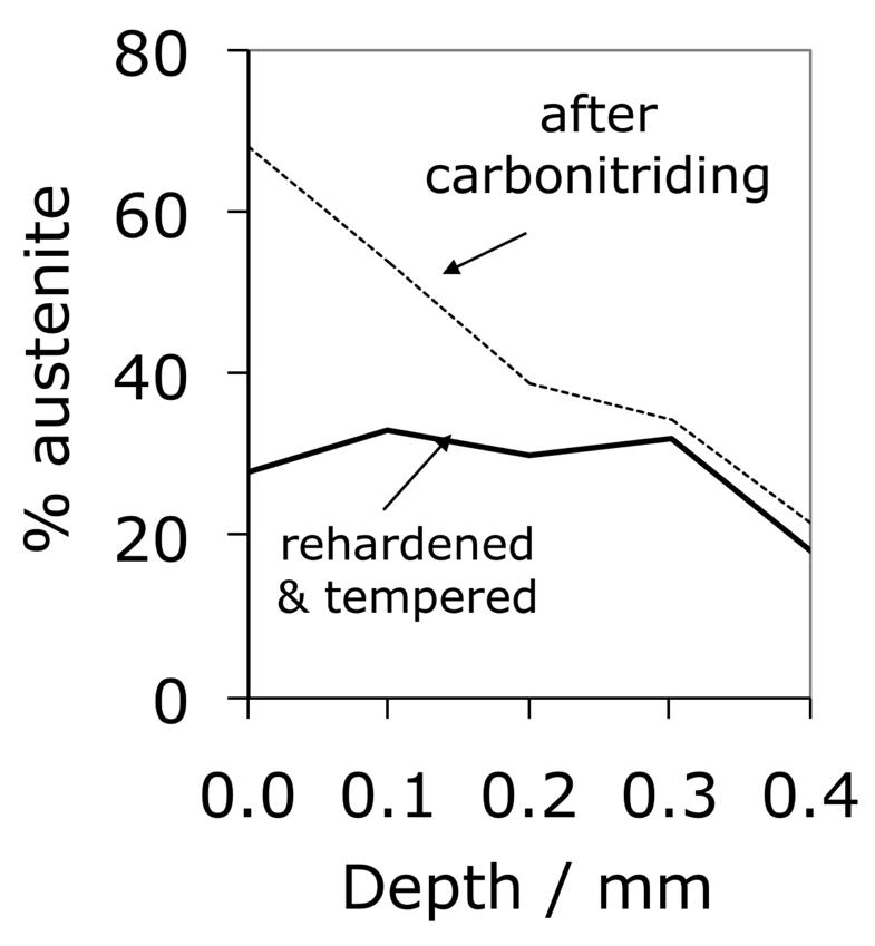
Carbonitrided samples contain significant concentration gradients with corresponding variation in the quantity of retained austenite as a function of depth. The region in close proximity to the free surface retains the most austenite and hence is in a relatively soft condition, Fig. 18; if austenitisation subsequent to surface treatment leads to decarburisation then the softening of the surface can be a result of decarburisation, in which case the retained austenite content at the surface would also be reduced [162]. A re-hardening heat treatment can lead to some homogenisation of the interstitial solutes, thus restoring the hardness on quenching, Fig. 18b.
 (b)
(b) 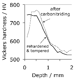
Whereas case-hardened bearings can lead an optimum gradient in properties for onerous applications, the production process is necessarily more complex and expensive when compared with through-hardened bearings. In M50NiL, the carburising process has been shown to lead to small changes in bearing ring dimensions which may add to subsequent distortions caused by heat-treatment [163]. The additional cost may not be the determining factor when it comes to aerospace bearings; alloys suitable for case hardening and service at elevated temperatures are discussed in detail in section 8.
Steels designed for through-hardening may also be induction hardened, a treatment which is relatively cheap and can routinely produce a surface hardness of 60 HRC in 52100 type steels. Because of its short duration the process is not associated with significant decarburisation. The time for the induction treatment can range from seconds for balls and rollers, to several minutes for bearing rings some 2 m in diameter, whose surfaces rotate through a stationary induction coil [164]. The austenitisation treatment (\( \approx 840\)°C) takes about 60s or less, after which the component is quenched — the austenite grain size in the treated region is therefore relatively fine, resulting in better toughness [21]. Selected regions of the sample can be hardened and complex shapes are possible using multiple frequency induction. It is not obvious from the literature whether the process is sensitive to the composition of the steel as long as the hardenability is sufficient given the typical cooling rates involved. However, as will be seen in section 18.3, the residual stress profile that results from the induction treatment can be a function of the hardenability of the steel.
Plasma-immersion ion implantation has been used to introduce nitrogen into the surface of 52100 steel. To achieve a hardness in excess of 800 HV requires the steel to be heated to 500°C for some 3–5 h in order to obtain hardening to a depth of about 40 µm [165]. Surprisingly, the increase in surface hardness is due to the formation of iron nitrides rather than chromium nitrides which ought to be more stable. It is possible that the chromium concentration is insufficient in 52100 steel, which is not designed for this purpose.
The rather shallow nature of the plasma implantation raises difficulties because in practice, damage is most pronounced deeper into the steel during rolling contact. On the other hand, independent work on the hard turning of the same steel found that a compressive stress over a depth of 50 µm induced by the machining reduced the propensity for spalling, presumably because buried cracks then find it more difficult to break the surface [167, 166]. However, this interpretation may be uncertain given that the inner races were honed prior to testing, a process which would definitely modify the state of stress at the surface [168]. More work is needed to understand the influence of shallow surface treatments on bearing life, because it is found in comparisons between treated and non-treated bearing raceways that both of them end up with a similar pattern of residual stress after being exposed to rolling contact cycles [166].
Strength
Strength of Austenite
As described in section 1, the carbon concentration of the austenite in 52100 steel following a typical austenitisation heat treatment is less than 0.86 wt%. It is therefore not particularly strong, as shown by the data in Table 6, even at low temperatures, compared with the overall strength of the steel in its quenched and tempered condition. This means that during deformation, any retained austenite will accommodate more plastic strain than the remainder of the microstructure which is much harder [202, 201], and transform into stress- or strain-induced martensite during the early stages of service. Cyclic deformation tests described in section 5.3 show that much of the retained austenite decomposes into martensite during the very first cycle.
The austenite in such bearing steels is in contrast to the much higher carbon retained austenite found in association with bainite in silicon-containing steels where it is in fact the hardest phase in the structure [203] and hence is much more stable during plastic deformation [204].
| Temperature / °C | 300 | 400 | 700 | 800 |
|---|---|---|---|---|
| 0.2% proof strength / MPa | 292 | 277 | 92 | 78 |
It is reported [205] that austenite in 52100 steel exhibits a Bauschinger effect whereby plastic deformation becomes easier when the sense of strain is reversed. The intensity of the Bauschinger effect increases when the supercooled austenite is subjected to reversed loading at lower temperatures. The exact mechanism of the effect has not been revealed but is speculated, for example, to be either because of damage accumulating at the undissolved carbides present in the austenite during the first loading, or because of the temperature dependency of the stacking fault energy of austenite. Identical tests conducted on the steel austenitised at a higher temperature to dissolve all the cementite would be informative. It is not obvious how this information can be exploited in constitutive modelling or the calculation of distortion and residual stress.
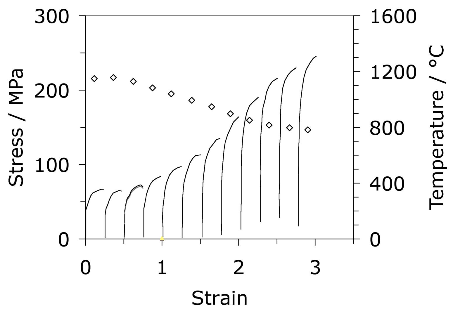
A large part of the shaping of bearing steels consists of hot deformation carried out in several stages of reduction. Fig. 23a shows how the stress and strain behaviour of the austenite changes in a simulated hot-deformation process [14]. More comprehensive isothermal compression data extending to larger strains [207, 206] covering strain rates in the range 0.1–10 s−1 and 950–1150°C show that for all of these conditions, the austenite in 52100 steel dynamically recrystallises during deformation. This can be deduced from the fact that the compressive stress versus strain curve exhibits a peak followed by softening associated with recrystallisation (there are some recent metallographic data to support this conclusion [208]). The peak stress ( \(\sigma_p \() in the stress versus compressive strain is, for these experiments, given in a standard empirical form commonly used to describe constitutive relations:
where \(Z \( is the Zener-Hollomon parameter [209] and \(\dot\epsilon \( is the strain rate. The variation in tensile hot-ductility as measured using the reduction in area of the test sample is illustrated in Fig. 23b. The dramatic decrease at the highest of temperatures is believed to be caused by incipient melting [210] but the large decrease at about 950°C has not been adequately explained, but could be associated with the precipitation of carbides within the austenite. The experiments below about 800°C may involve the presence of some ferrite [210]. A similar expression is available for the peak strain which can be related to that needed to induce the onset of recrystallisation [206].
 (b)
(b) 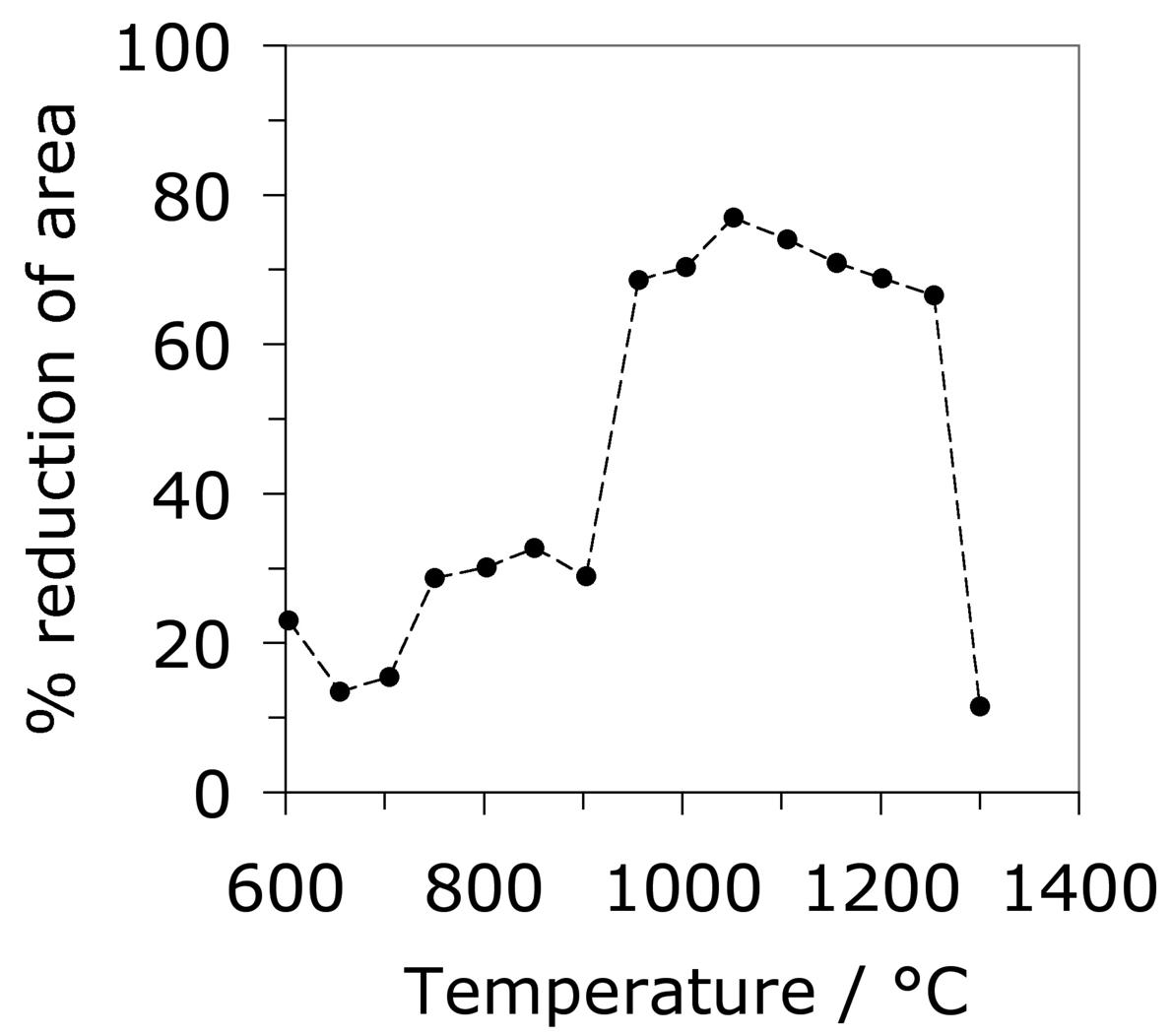
In an interesting study where 52100 steels is repeatedly cycled through the α + θ ⇆ γ + θ transformation with the material under a static tensile stress <20 MPa, Oelschlägel and Weiss [211] observed an elongation in excess of 500% prior to fracture. This comes from the accumulation of transformation plasticity over the 260 cycles utilised. They labelled the phenomenon as 'superplasticity' which in modern terminology involves grain boundary diffusion and grain rotation.
Cyclic Stress-Strain Properties
It is useful in the context of bearing steels to study cyclic stress-strain behaviour because the work hardening behaviour in the early stages of deformation defines the shakedown limit. The information may also be exploited in the elastic strain based Hertzian treatment of rolling-contact stresses into the elastic-plastic regime. Fig. 24 shows the cyclic stress-strain behaviour of 52100 steel in its quenched and tempered martensitic condition but containing 11% of retained austenite [29]. The net elongation of the sample after the completion of the first cycle, as indicated by the failure of the loop to close, is largely a consequence of the transformation of the majority of retained austenite during the first application of the tensile stress. Only 4% of the austenite remains after the first cycle and this quantity does not diminish significantly with further cycles7. Subsequent loops show ever decreasing closure failure, and are essentially closed after about five cycles. This is because the material cyclically hardens, so that in a test where the stress amplitude is maintained constant, the degree of macroscopic plasticity detected decreases, as is evident from the loop illustrated for the 200th cycle. In contrast, when the strain amplitude is maintained constant, the stress required increases empirically as \(11,580(0.5\Delta \epsilon_p)^{0.137} \( MPa, where \(\Delta\epsilon_p \( is the plastic strain range [212].
In contrast to the behaviour of 52100 steel in its martensitic condition, softening is observed to occur in the early stages of cycling when the microstructure is bainitic with very little retained austenite in the initial state.
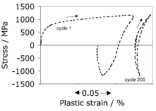
Notice that the loops illustrated in Fig. 24 have an unconventional shape once the austenite is rendered innocuous. This shape is often described as that of a 'sickle', as opposed to one which is symmetrical about the zero stress and zero strain point. The peculiar shape is the outcome of non-linear elasticity exhibited by 52100 steel both in the martensitic and bainitic conditions [213, 178]. It is well known [214, 215] that iron at very large stresses shows deviations from Hooke's law when the elastic strain exceeds about 1–2%. The deviation is expected because the way in which the force between atoms varies as a function of interatomic spacing is not symmetrical as the force changes sign (an anharmonic lattice potential). The stress-strain relationships become:
with the values of the parameters for 52100 steel listed in Table 7. A consequence of the large stresses associated with bearings in service is that the usual Hertzian contact analysis (section 15.1) based on a fixed Young's modulus may require modification [178], although the fact that the real scenario during rolling-contact requires an elastic-plastic analysis may be of overriding importance. It is odd, though, that similar non-linearity in the stress versus elastic strain curve has not been reported for another steel (100CrMnMo8, Table 1) during the cyclic testing of samples in both the martensitic and bainitic conditions [216].
| Process | Hydrogen | Nitrogen | Oxygen |
|---|---|---|---|
| Air melting + vacuum degassing | 3.2 | 120 | 46 |
| Air melting | 4.8 | 150 | 67 |
| + 1 vacuum arc remelt | 1.8 | 80 | 37 |
| + 2 vacuum arc remelts | < 1 | 60 | 9 |
| + 3 vacuum arc remelts | < 1 | 50 | 5 |
| Vacuum induction melting | < 1 | 85 | 21 |
| Vacuum induction melting + vacuum arc remelting | < 1 | 60 | 6 |
Sulphur manifests within the steel in the form of compounds, particularly manganese sulphide. The sulphides can form in isolation or deposit on to existing oxide particles, with the fraction of oxides encapsulated by sulphides increasing as the oxygen concentration is reduced [122]. The sulphur concentration is controlled during the ladle treatment of molten steel by partitioning from the melt and from the atmosphere within the ladle, into the slag [136]. The partial pressure of sulphur and oxygen during this stage is less than 10−6 atm and gaseous sulphur then replaces oxide ions in the slag to release oxygen and in the process becomes entrapped within the slag. Similarly, sulphur dissolved in the metal is captured as it substitutes for oxide ions in the slag. The capacity of a slag to absorb sulphur is thus given by the product \( \text{S}_{\text{slag}} \times \sqrt{p_{\text{O}_2}/p_{\text{S}_2}} \) where \( p \) represents the partial pressure of the gaseous species concerned. This capacity correlates well with the basicity of the slag, most simply defined as the ratio of the basic oxide CaO to acidic oxide SiO2. Specific additions of lime help to remove sulphur via the reaction \( 2\text{CaO} + 2\text{S} \rightarrow 2\text{CaS} + \text{O}_2 \).
The role of sulphides in the 52100 type bearings steels has been somewhat confused. Sulphides have been known for a long time to increase machinability by acting as chip-breakers. Some papers suggest that the expansion coefficient of MnS is less than that of iron [137] whereas others explain the insensitivity of rolling contact fatigue strength to sulphur concentration by assuming that the coefficient is relatively large, so that tensile stresses do not develop around the inclusion [138]. Early work has even suggested that concentrations in the range 0.013–0.043 wt% result in an improvement in fatigue performance because the sulphides coat the relatively brittle oxides present in 52100 type steels [143, 140, 142, 139, 141]; the sulphides have also been suggested to act as barriers to the propagation of damage (butterflies, section 21.2.3) originating at alumina particles [144]. This is unlikely to be the case with modern bearing steels which have much higher levels of overall cleanliness. Indeed, it has been pointed out that a minimum sulphur content is appropriate for optimum fatigue resistance in steels containing low concentrations of oxides and titanium compounds [136, 145]. Sulphide particles tend to be plastic during hot-deformation and any detrimental effect is mitigated by large reduction ratios [146]. All kinds of inclusions can be expected to contribute to the initiation of cracks when the contact stresses are very large, such as those used to accelerate tests ( \(> 4000 \( MPa) [147]. Excessive local concentrations of sulphides or oxysulphides can lead to low melting-temperature eutectics which then compromise the ability to hot-deform the steel [148].
Steels for Surface Modification
There are many processes that can be used to alter the properties of the steel at its surface. For example, 52100 steel can be laser treated to produce a surface hardness in excess of 1000 HV [105, 149, 150]. When the laser conditions are such that surface melting occurs, 52100 steel solidifies into a structure consisting of ledeburite eutectic, large quantities of retained austenite and martensite; this mixture is not considered to be optimum from the point of view of rolling contact fatigue [105]. Laser glazing, in which the surface is rapidly heated and re-solidified also results in a hard structure to a depth of about 100 µm and has been used in alloys such as M1 to eliminate the coarse carbides that result from conventional solidification, and to introduce a compressive stress at the surface [151]. Ion implantation of 52100 steel with carbon beyond a critical dose has been shown to lead to a virtually zero wear rate in pin-on-disc tests; the implantation left much of the carbon in solid solution with the remainder as ε-carbide, without introducing additional retained austenite [152]. Nitrogen implantation also increases the hardness and induces a compressive stress extending many tens of micrometres into the surface of 52100 steel [153]. Titanium implantation to a depth of about 0.1 µm changes the friction characteristics and adhesive wear behaviour [154], although the detailed mechanisms responsible for these changes do not seem to have been investigated.
This section deals, however, with processes that change the chemical composition of the surface to a depth extending a millimetre or so, such that the lower carbon concentration of the core gives greater toughness in circumstances where structural integrity can otherwise be compromised. Case carburised, nitrided or carbonitrided components have the advantage of a hard surface metallurgically bonded to a tough core. Carburising also introduces a compressive stress ( \(\approx 200\text{--}300 \( MPa) in the surface, resulting in an improvement in fatigue performance [155]; this combination makes surface-hardened raceways more resistant to indentation when compared against through-hardened bearings [156]. Whereas both through hardened and surface hardened steels can serve well in ordinary applications where rolling contact fatigue or wear are the prime concerns, case hardened bearings because of their tough cores serve better in circumstances where bending, torsion and impact stresses have to be resisted [157]. Surface modified bearings are therefore used widely in automotive applications, or when large bearings with diameters in excess of 3 m have to be made where it is impractical to expect through-hardening. It is argued that in addition to the residual stresses, the partial transformation of retained austenite into martensite during cyclic loading leads to hardening which contributes to the improved resistance in four-point bending fatigue tests [155].
The depth of hardening is usually less than 1 mm, although greater penetration may be required if the bearing surface requires extensive grinding following heat-treatment. The properties of the core can be adversely affected by the abnormal growth of austenite grains during heat-treatment so microalloying with vanadium has been proposed as a solution [34]. The chemical composition is listed in Table 1 and relies on the precipitation of V(C,N) which pins the austenite grains to a size of about 22 µm on treatment at 930°C for 5 h. For the same reason, microalloying with aluminium and nitrogen, or niobium, leads to an improvement in the rolling contact fatigue life of carburised surfaces when the primary failure mechanism is by the propagation of cracks along the austenite grain boundaries [158, 159]. The size can also be controlled and refined by repeated austenitisation and quenching (e.g. double hardening) [160]. The double hardening is now routinely implemented for case-carburised bearings [161].
Carbonitrided samples contain significant concentration gradients with corresponding variation in the quantity of retained austenite as a function of depth. The region in close proximity to the free surface retains the most austenite and hence is in a relatively soft condition, Fig. 18; if austenitisation subsequent to surface treatment leads to decarburisation then the softening of the surface can be a result of decarburisation, in which case the retained austenite content at the surface would also be reduced [162]. A re-hardening heat treatment can lead to some homogenisation of the interstitial solutes, thus restoring the hardness on quenching, Fig. 18b.
 (b)
(b) 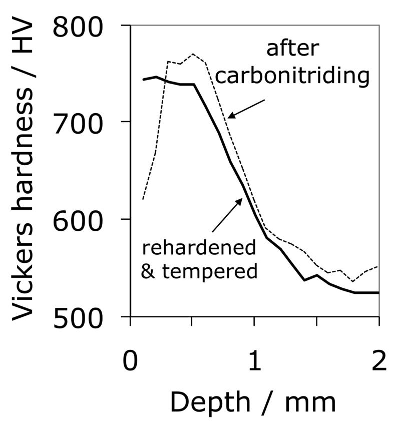
Whereas case-hardened bearings can lead an optimum gradient in properties for onerous applications, the production process is necessarily more complex and expensive when compared with through-hardened bearings. In M50NiL, the carburising process has been shown to lead to small changes in bearing ring dimensions which may add to subsequent distortions caused by heat-treatment [163]. The additional cost may not be the determining factor when it comes to aerospace bearings; alloys suitable for case hardening and service at elevated temperatures are discussed in detail in section 8.
Steels designed for through-hardening may also be induction hardened, a treatment which is relatively cheap and can routinely produce a surface hardness of 60 HRC in 52100 type steels. Because of its short duration the process is not associated with significant decarburisation. The time for the induction treatment can range from seconds for balls and rollers, to several minutes for bearing rings some 2 m in diameter, whose surfaces rotate through a stationary induction coil [164]. The austenitisation treatment (\( \approx 840\))C) takes about 60s or less, after which the component is quenched — the austenite grain size in the treated region is therefore relatively fine, resulting in better toughness [21]. Selected regions of the sample can be hardened and complex shapes are possible using multiple frequency induction. It is not obvious from the literature whether the process is sensitive to the composition of the steel as long as the hardenability is sufficient given the typical cooling rates involved. However, as will be seen in section 18.3, the residual stress profile that results from the induction treatment can be a function of the hardenability of the steel.
Plasma-immersion ion implantation has been used to introduce nitrogen into the surface of 52100 steel. To achieve a hardness in excess of 800 HV requires the steel to be heated to 500°C for some 3–5 h in order to obtain hardening to a depth of about 40 µm [165]. Surprisingly, the increase in surface hardness is due to the formation of iron nitrides rather than chromium nitrides which ought to be more stable. It is possible that the chromium concentration is insufficient in 52100 steel, which is not designed for this purpose.
The rather shallow nature of the plasma implantation raises difficulties because in practice, damage is most pronounced deeper into the steel during rolling contact. On the other hand, independent work on the hard turning of the same steel found that a compressive stress over a depth of 50 µm induced by the machining reduced the propensity for spalling, presumably because buried cracks then find it more difficult to break the surface [167, 166]. However, this interpretation may be uncertain given that the inner races were honed prior to testing, a process which would definitely modify the state of stress at the surface [168]. More work is needed to understand the influence of shallow surface treatments on bearing life, because it is found in comparisons between treated and non-treated bearing raceways that both of them end up with a similar pattern of residual stress after being exposed to rolling contact cycles [166].
Strength
Tensile, Compressive and Bending Strength
Steels such as 52100 steel, when in a typically quenched and tempered condition, are not particularly ductile; the elongation in tension is barely 1–2% so meaningful tensile test data are difficult to come by and hardness or bending strength is often reported instead. Hardness in the range 59–66 HRC has been shown to correlate positively with rolling contact fatigue life, and greater hardness is associated with reduced wear in the bearing tracks [169]; this correlation of wear against hardness fails in tests involving the unlubricated sliding of 52100 steel against a much harder ring [170] because of the effects of heat generation on material removal.
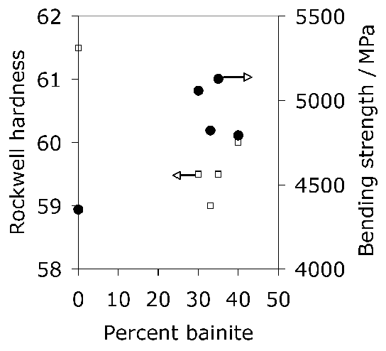
Tensile tests do contain a wealth of information not accessible from hardness data; for example, the reduction of area and ultimate tensile strength feature in the rationalisation of uniaxial fatigue tests [171]; the elongation and proof strength similarly feature in the estimation of fatigue crack growth rates [172, 174, 173]. The reduction of area measured at ambient temperature has been reported at less than 0.5% [175]; some temperature-dependent properties are listed in Table 5. The 52100 steel is not intended for elevated temperature service but the data are nevertheless useful in finite element analysis of machining processes. Fig. 19 shows typical values of the bending strength for a variety of microstructures [176]; the stresses involved are large and it is difficult to see how these can be interpreted in an applicable manner. It is not clear, for example, why the hardness shows a trend which is opposite to the bending strength as the microstructure is varied. The fact that the mixed microstructures are stronger than the fully martensitic sample is not significant because the former also contained untempered martensite.
| Temperature / °C | 20 | 200 | 400 | 600 | 800 |
|---|---|---|---|---|---|
| Yield strength / MPa | 1394 | 1161 | 908 | 414 | 303 |
| Ultimate tensile strength / MPa | 1748* | 2151 | 1551 | 934 | 311 |
| Reduction of area / % | 1.0* | 2.0 | 1.6 | 1.5 | 1.0 |
| Young's modulus / GPa | 208 | 163 | 154 | 113 | 103 |
Some general statements indicate that 52100 steel in its usual martensitic condition (with 11% \(\gamma_r \() or when transformed to lower bainite at temperatures below 300°C (without \(\gamma_r \(), exhibit a 0.2% proof strength in the range 1400–2200 MPa and an ultimate tensile strength between 2150 and 2450 MPa [178]. The higher values correspond to martensite and the strength decreases as the bainite transformation temperature is increased. Some specific data for the influence of the bainite transformation temperature are illustrated in Fig. 20. The ductility in the bainitic condition is always larger than the minimal plasticity exhibited by the tempered martensite structure in this steel; this may explain why the life of lower bainitic bearings operating in water-containing environments exceeds that of quenched and tempered varieties [179].
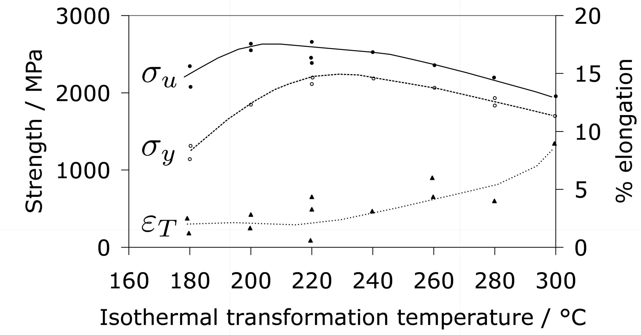
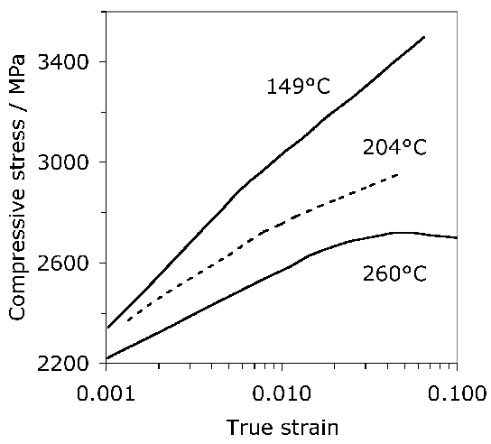
Fig. 21 illustrates plots of the true compressive strength against the true strain in compression, for a variety of tempering temperatures [182]. Compressive strength is of course relevant in bearing applications, since the resultant shear is what leads to damage accumulation. The data are as expected, since more of the carbon should be retained in solid solution within the martensite as the tempering temperature is reduced. It is interesting that the form of the stress versus strain curve changes with a reduction in the rate of work hardening as the tempering temperature \((T_T) \( is increased. Some of this reduction may be associated with the fact that the amount of retained austenite in the microstructure decreases as the \(T_T \( is increased [60] because the stress-induced transformation of such austenite enhances the work-hardening rate. However, it is also well known that stronger steels work harden more rapidly because they contain a greater number density of obstacles to dislocation glide. A work hardening exponent defined as \(n=d\,\ln\sigma/d\,\ln\varepsilon_p \( for \(\varepsilon_p=0.005 \( is in the range 0.06–0.1 depending on the heat treatment and retained austenite content [182].
A more comprehensive description of strength, as a function of temperature, strain and strain rate is required for the purposes of finite element modelling, for example in the numerical simulation of machining. Umbrello et al. have created precisely such a framework for steel 52100, which seems to work well in empirically representing the constitutive behaviour of the alloy over a wide range of conditions [183]. Oddly, they also included hardness as a parameter in the functional for flow stress, on the basis that it is a parameter which is important in the characterisation of machinability since tool wear becomes significant when the hardness exceeds about 45 HRC. However, their interpretation of hardness is unconventional, that it is a consequence of heat treatment and independent of mechanical work. Although this is an inconsistency, the method is adequate for the purpose of numerical modelling presumably because the work hardening coming from mechanical work is handled separately in the grand scheme.
Some unusual heat and thermomechanical treatments have been used in an attempt to improve the homogeneity, ease of spheroidisation, tensile ductility and toughness of 52100 type steels [184, 185]. The experimental design was based largely on the notion that carbides within the structure, which do not dissolve during austenitisation, are detrimental to these particular properties. The heat treatments were therefore more complex, as follows:
- Austenitisation at the higher than normal temperature of 900°C followed quenching to martensite and tempering at 250°C for 1 h. Because of the higher carbon concentration introduced into the austenite, the martensite was harder (64.5 HRC) and it was not possible to measure the tensile properties due to brittle failure of the sample before macroscopic yield, possibly due to microcracking of the martensite.
- Austenitisation at 1150°C, an interrupted quench into hot-oil at 150°C to avoid quench cracking, cooling to ambient temperature, followed by a reaustenitisation at 900°C for just 20 min in order to generate a refined austenite grain size, and then oil quenching to martensite and tempering at 250°C for 1 h. This also led to strong and brittle tensile test samples.
- The martensite-start temperature following austenitisation at 900°C was estimated to be 250°C; a partly bainitic microstructure was therefore produced by isothermal transformation at 255°C for 1 h, followed by cooling to ambient temperature so that some of the residual austenite transformed into untempered martensite. This sample exhibited the best toughness and an ultimate tensile strength of some 2150 MPa. The toughness improved further when a double austenitisation heat treatment (as above) was utilised prior to isothermal transformation.
- It has been demonstrated that undissolved carbides in 52100 steel can be significantly refined by 'warm working', i.e., plastic deformation at about 650°C. The process of refinement is more rapid when the initial microstructure is tempered martensite as opposed to pearlite [186, 55, 187]. It is interesting that warm working can yield such a fine mixture of chromium-stabilised cementite and ferrite grains that 52100 steel becomes superplastic during tensile testing using slow strain rates at 650°C, resulting in an elongation which exceeds some 1000% [55, 188]. Fig. 22 shows the differences to be expected when the steel is heat-treated to produce untempered martensite beginning with two different starting conditions, the warm-worked and the soft-annealed conditions.
- Thermal cycling has also been shown to lead to a refined microstructure in high-carbon steels [189]. The first stage is to dissolve all the carbides and quench the austenite. The martensite is then heated to a temperature just within the γ+θ phase field so that the austenite grains which form are pinned by cementite. The fine austenite grains are then quenched again and the cycle repeated until a point of diminishing returns.
- Thermomechanical processing of the type used routinely for mass-produced low-alloy steels has the potential for significant reductions in the austenite grain size. The process involved the deformation and repeated recrystallisation or pancaking of austenite grains prior to their transformation [190]. Xie et al. [191] studied this for a 52100 type steel, but the alloy is not designed for purpose because it lacks the required number density of stable carbides capable of pinning the austenite grain boundaries, and hence did not achieve significant changes in the final microstructure. Mechanical properties were not reported.
- Bearing steels are usually hot-rolled or hot-forged; a reduction in the finish rolling temperature to some 750–800°C has been shown to refine large carbides and to significantly reduce the time for spheroidisation [192]. Any grain boundary cementite should also be broken up by this process.
Data are not available for properties such as rolling contact fatigue for the steel in these special conditions. In a case where RCF was in fact measured [185], finer cementite dispersions obtained by first transforming the steel to pearlite at 650°C, reaustenitising at 900°C and then implementing the quenched and tempered state, led to an improvement in fatigue life. It was concluded that it is not necessary to dissolve all of the cementite in order to optimise the fatigue life.
Another unusual heat-treatment aims at stabilising the retained austenite [91]. After quenching to ambient temperature, the steel is held below MS at −60°C for a prolonged period of 10 h in order to allow some of the retained austenite to transform isothermally into martensite. This apparently stabilises the remaining austenite to both sub-zero treatment, subsequent tempering and deformation. The deformation associated with the formation of isothermal martensite is said to introduce dislocations in the remaining austenite which mechanically stabilises the phase [195, 194]. Isothermal martensite is rarely discussed in the bearing steel literature but its mechanism and microstructural characteristics are well established in the wider literature [198, 196, 199, 200, 197].
Hardness
The hardness of 52100 type steels can be estimated using a rule of mixtures with the assumption that the hardnesses of martensite, bainite, pearlite and austenite are given by 64, 35, 29 and 17 HRC [217]8. The method is likely to be reasonably accurate as long as the steel does not contain much bainite because it is unreasonable to assign a single value of 35 HRC to this phase since isothermal transformation to a fully bainitic structure at 250°C following austenitisation at 840°C leads to a hardness close to 60 HRC [218]. The concept is inconsistent with the data presented in Fig. 19. On the other hand, transformation at 290°C leads to a hardness of between 38–39 HRC [219].
The tempering time to reach an equivalent hardness during low-temperature heat treatment has been expressed as an equivalence parameter in the context of 52100 type steels:
where the subscript refers to the reference tempering temperature of 110°C and \(Q \) is an empirical activation energy. \(t \) is the tempering time and T the absolute temperature [220]. The experiments used to develop this equation covered temperatures up to 500°C, and in recognition of the fact that more than one mechanism might operate, two different activation energies were derived.
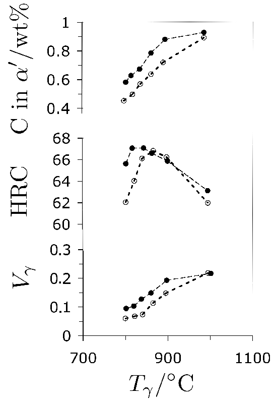
Increasing the austenitisation temperature when heat treating 52100 steel does not, beyond about \( T_\gamma = 840 \)°C, increase the hardness of the quenched or quenched and tempered structure, Fig. 25 [221]. This is because although the carbon concentration of the austenite, and hence of the martensite that forms on quenching, increases, so does the amount of relatively soft retained austenite. Even this conclusion is not completely safe since the hardness of martensite ceases to increase as a function of its carbon concentration once about 800 HV has been achieved [223, 222].
 (b)
(b) 
(c)
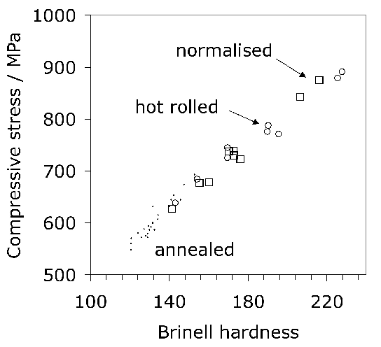
Cold forging components into approximate shape can minimise the costs associated with machining, as long as the process does not involve large stresses and assuming that wear on dies is not the cost-determining factor. The ability to cold-forge bearing steels is related approximately to its compressive strength; it has been shown that the strength at a true strain of 0.2 correlates strongly with the hardness and does not depend on the starting microstructure within the limits studied [225]. Fig. 26 shows that the correlation holds irrespective of whether the steel is in its annealed, hot-rolled or normalised condition, for a large variety of alloys included in the analysis.
Microcracking
It has been emphasised that the austenite grain size should be kept small enough to avoid the fracture of untempered, high-carbon martensite [226]; some examples of microcracks are illustrated as a function of the austenite grain size in a high-carbon steel, Fig. 27. Microcracking of this kind has been reported for 52100 steel quenched after austenitisation at about 1100°C [226]. Studies on carburised steel have shown that the cracks are known to adversely influence the fatigue properties [227]. Fracture can also occur at the austenite grain boundaries by impingement with large martensite plates [228].
It was at one point argued that such cracking is an artefact associated with plates of martensite in the close proximity of the metallographic sample surface, i.e., a function of metallographic specimen preparation [229]. Subsequent work, reviewed in [226] indicated that the cracks are indeed a consequence of martensitic transformation rather than a surface effect. Delayed acoustic emission signals after quenching to martensite have been shown to result from cracking, and these presumably arise from the body of the material rather than just the surface [230].
The microcracking has been attributed to impingement between plates of martensite forming on different variants of habit planes in the same austenite grain [231, 232, 233]. Experiments in which the bearing steel is cooled slowly through the martensite transformation temperature range, or cooled through it in a stepwise manner, result in fewer microscopic cracks because the plates that form first acquire a degree of tempering and possibly due to the reduction in quench stresses. Any reduction in cracking due to the tempering of martensite is at first sight surprising since the heat-treatment is an aftermath to the formation of martensite. One reason for the apparent reduction is healing by cementite precipitation at microcracks [234]. There may also be a role of dimensional changes induced in the martensite by tempering, and the associated plasticity, on the reduction in cracking tendency [235].
Marder et al. [231] concluded that the tendency for cracking is not a function of the austenite grain size when the latter is coarser than 100 µm [231], but even more refined austenite grains do reduce the tendency for cracking [232]. Recent work has interpreted this dependence in terms of the ability to transfer load onto the martensite as the composite mixture of α'+γ is deformed [236]. The spacing between cracks in long martensite plates corresponds approximately to the stress transfer length of composite theory, and an austenite grain size (and hence martensite plate size) which is finer than this transfer length dramatically reduces microcracking. This may explain the contention that there is a critical α'-plate size below which cracking does not occur [237].
An increase in the carbon concentration of the martensite can reasonably be expected to enhance cracking, either by inducing a lath to plate martensite morphological transition, or by making the martensite more brittle through hardening or because the lattice becomes more tetragonal [238]. However, when the concentration exceeds about \( \approx 1.4 \text{ wt%} \), there is a transition in the habit plane of martensite from \( \{225\}_\gamma \) to \( \{259\}_\gamma \) accompanied by a reduction in cracking [232]. There are multiple explanations for this, based for example on the change in angle of impingement between colliding plates, or the sequence in which successive plates form.
 (b)
(b) 
(c)
 (d)
(d) 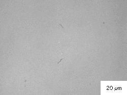
Spheroidise Annealing
Steels supplied to the bearing manufacturer for making raceways are in the form of tubes or forgings whereas the rolling elements are made by cold-forging drawn, spheroidised-annealed wire. The aim of spheroidise annealing is to facilitate machining, and warm- and cold-forming operations, by inducing a microstructure which is a mixture of relatively coarse cementite particles and ferrite. The roughness of machined surfaces is also reduced in the process [239]. Reasonably large cementite particles and a small number density is conducive to less wear on the tools used for machining; lamellar carbides of the type associated with incomplete spheroidisation lead to enhanced tool-degradation [240]. A consistent spheroidise-annealed microstructure results in a reproducible volume change during heat treatment, optimised machining allowances and reduced costs.
Spheroidisation reduces the hardness of the steel supplied to a bearing manufacturer to about 230 HV [241]. The yield and ultimate tensile strengths for 52100 steel in this condition are 455 and 635 MPa respectively, with an elongation of 36% [187]; the yield here presumably corresponds to a 0.2% proof stress. Comprehensive data for the spheroidised state are presented in Fig. 28, but it is worthy of note that the strength can vary significantly as a function of position because of chemical differences caused by segregation during casting [242].
Recent work has shown that the hardness is not sensitive to the substitutional solute content [243]. On the other hand, the kinetics of spheroidisation have long been known to depend both on the chromium and carbon concentrations. A higher carbon concentration promotes spheroidisation, apparently by providing a greater initial number density of nucleation sites, and the action of chromium manifests by reducing the interlamellar spacing of pearlite, which is often the starting structure for a spheroidising anneal [52, 51]. Attempts to reduce the carbon concentration of 52100 in order to avoid undissolved cementite have had limited success because of the inability of the hypereutectoid steel to be readily spheroidised [52].
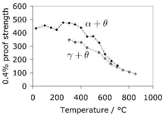
There are two essential methods for soft-annealing of the 52100 type steels: the first involving continuous spheroidisation during cooling from the partially austenitic γ+θ condition, and the other utilising isothermal annealing at a temperature which is less than that at which austenite begins to form. The former method is more suited to hypereutectoid steels because it reduces the proeutectoid cementite layers at the prior austenite grain boundaries into spheres, and subcritical annealing to hypoeutectoid alloys where it is said to be more rapid [245]. Finer microstructures in general tend to spheroidise more rapidly during subcritical annealing [246]; this might be expected since the process is driven by the minimisation of total interfacial area per unit volume. In some cases the steel is first heat-treated to produce the finest possible pearlite to permit more rapid dissolution of the carbides during the spheroidising heat treatment [247]; it has been demonstrated for 52100 type steel that fine, lamellar pearlite dissolves at a greater rate than spheroidised cementite of the type often present in the steel supplied to the bearing manufacturer [248]. More complex but possibly less practical processes can involve thermal cycling about the eutectoid temperature [249, 250].
The details of the microstructure in either the soft-annealed or any other structural state influences the properties obtained following the subsequent hardening heat treatment. The kinetics of austenitisation are sensitive to the initial shape and size of ferrite grains and cementite particles [251]. The size of the austenite grains and hence the size distribution of subsequent martensite, and the dissolution rates of the carbides (related the composition of martensite) have been shown to depend on the initial structure [252].
When the starting microstructure is pearlitic following hot-rolling (Fig. 3) with a hardness of about 340 HV [241], it takes many hours of isothermal heat-treatment to achieve the required degree of spheroidisation, during which the steel must be protected against decarburisation, for example, by using a controlled furnace-atmosphere containing a few percent of hydrogen and carbon monoxide [247, 253, 254]. One purpose of continuous annealing is to avoid the formation of lamellar pearlite. When the steel is heated into the two-phase γ+θ phase field, the presence of sufficient cementite particles can prevent the onset of pearlite. This is because the existing cementite particles absorb the carbon that is partitioned at the γ/α transformation front in a process referred to as the 'divorced eutectoid transformation', which does not rely on the cooperative growth of ferrite and cementite [255]. The concept of divorced pearlite has been known for a long time [256, 257, 259, 258] as has its role in generating the spheroidised state during continuous cooling [260, 246] or through heat treatment [261]. It was known as early as 1920 [256] that the presence of carbide particles in hypereutectoid steels led to the formation of globular pearlite, in which the cementite phase is spheroidised during transformation, as illustrated in Fig. 29. A secondary effect is that this kind of divorced pearlite forms at a higher temperature during continuous cooling than lamellar pearlite [257]; this is because the latter requires the nucleation of cementite and the establishment of cooperative growth with ferrite in order to form.
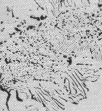 (b)
(b) 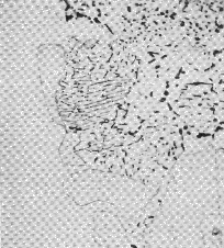
However, the detailed mechanism began to be actively discussed more recently [255, 262] and is illustrated schematically in Fig. 31a. Verhoeven has presented a quantitative model based on diffusion-controlled growth which is summarised here. During the transformation, when the mixture of austenite and cementite is supercooled below Ae1, fluxes are created towards cementite particles in both the austenite and ferrite, as illustrated in Fig. 31b. If the α/γ interface advances at a velocity v, then the amount of carbon partitioned must equal that absorbed in the cementite if equilibrium is to be maintained at the interfaces concerned:
If ΔT is written as the undercooling below the temperature at which ferrite may first form on cooling the mixture of austenite and cementite, and by representing the concentration differences in this equation using the Fe-C phase diagram, an approximate equation for the velocity of the α/γ interface is given by9:
This equation does not contain the average carbon concentration of steel because the diffusion distances λα and λγare inputs. By comparing this velocity against standard data for the growth of lamellar pearlite [263], it was possible to plot the line illustrated on Fig. 32 which indicates the domains in which the decomposition of a mixture of austenite and cementite particles should decompose to divorced or lamellar pearlite. Given that a finer dispersion of undissolved cementite particles favours the divorced form, lower austenitisation temperatures also discourage the formation of lamellar pearlite [264]. Decarburisation of the surface can eliminate proeutectoid cementite and thereby lead to lamellar pearlite in those regions with accompanying difficulties in processing [265].
The model [262] has been used to reasonable effect to explain the influence of chromium and manganese concentrations on the spheroidisation of an otherwise 52100 steel type steel, taking into account the change in equilibrium concentrations due to the substitutional solutes [243]. Unfortunately, the conclusions regarding a transition from divorced to lamellar pearlite are doubtful because no account was taken of the influence of Mn or Cr on the growth rate of lamellar pearlite; these elements have a strong effect on pearlite kinetics [266]. The influence of solutes in general on spheroidisation and divorced pearlite is only partly understood. For example, small concentrations (0.03 wt%) of hafnium promote the formation of divorced pearlite [258] but the mechanism has not been investigated. A large phosphorus concentration is known to retard spheroidisation but again, the mechanism is not clear [267]; the growth rate of cementite allotriomorphs at austenite grain boundaries does not depend on the phosphorus concentration of the steel [268]. Silicon has been shown experimentally to retard the spheroidisation process, probably because phase diagram calculations indicate that the solubility of carbon in austenite decreases [270, 269]. This simple interpretation would lead not only to a greater fraction of cementite, but should also diminish any concentration gradients due to capillarity effects within the austenite between coarse and fine particles, thereby providing a second mechanism for the retardation of coarsening. However, qualitative interpretations [269] based on the influence of silicon on the activity and chemical potential of carbon in the austenite are weak; for example, Fig. 8b of [269] identifies the chemical potential of carbon in cementite to be different from that in austenite, which is not correct given that there is an equilibrium between the two phases.
In an interesting study, induction annealing was used to produce divorced pearlite, i.e. spheroidised cementite, in a matter of minutes [271]. Undissolved cementite was preserved by rapid austenitisation of a 52100 type steel for 30s at 850°C. This was then transformed isothermally at 650°C for 17 min to produce the required microstructure with a hardness of about 235 HV.
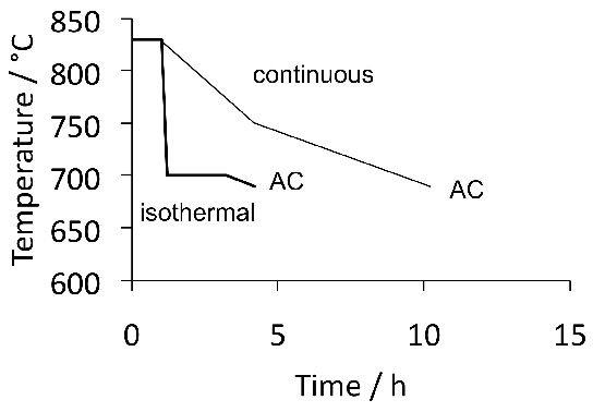
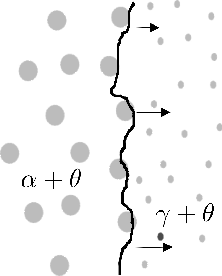 (b)
(b) 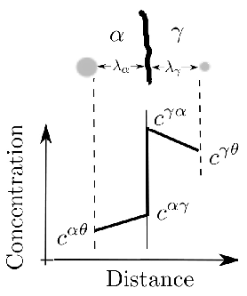
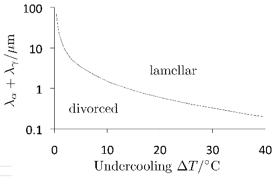
The purpose of spheroidisation is to coarsen and hence soften the microstructure, but there are consequences because the total amount of cementite is of the order of 15 vol.% in the 52100 type bearing steels, Fig. 4. The particles in the spheroidised condition have a size in the range 0.5–3 µm (the ferrite grain size in the range 15–25 µm [273]). The size of the carbides can be controlled using spheroidising anneals, followed by the usual quench and temper heat-treatments. Using the method, it has been demonstrated that there is an advantage from a fatigue point of view in having a fine dispersion in the soft-annealed condition, so that the carbides which are undissolved during austenitisation can also be small in size [274, 43]. There is another reason in favour of the refined cementite particles; the spheroidised steel is ring-rolled, i.e. cold-deformed into a ring form, during which much of the deformation is in the majority ferrite phase with the much harder cementite particles behaving relatively rigidly [273]. The resultant mismatch of strain between the two phases leads to the opening up of voids at the interfaces between the larger cementite particles and the matrix, Fig. 33. Similar voids are found at the ends of the larger (primary) alloy-carbides in processed M50 steel (Table 8) [275]. If these are not healed in continued or subsequent processing then the voids or weakened interfaces must contribute to the initiation of fatigue damage and is one explanation why the refinement of grain size in M50 does not contribute to improved rolling contact fatigue performance [276].
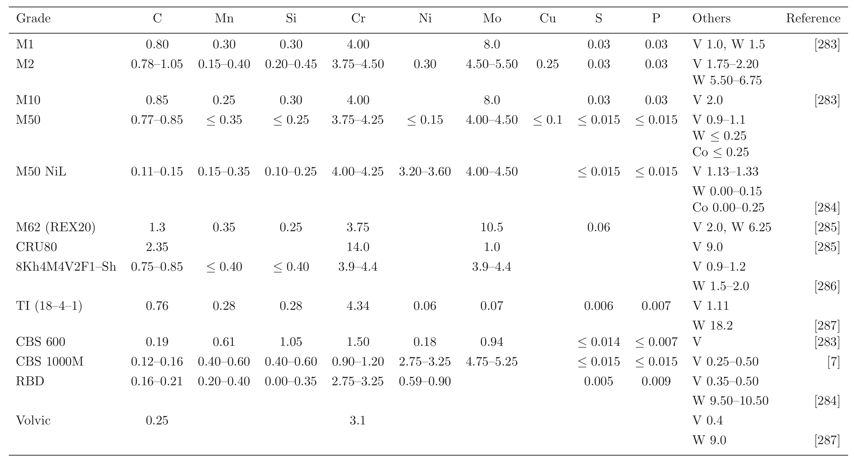 |
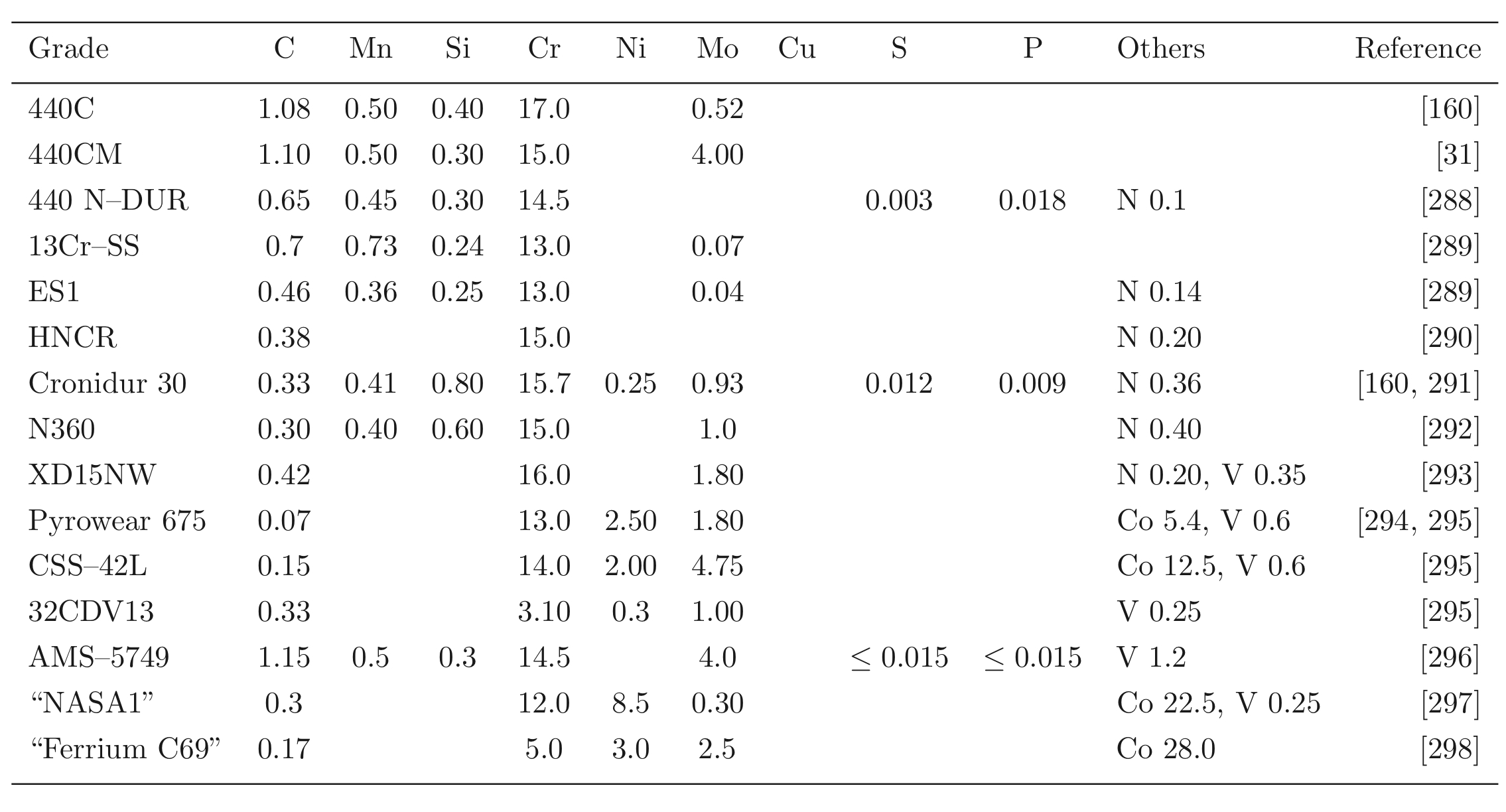 |
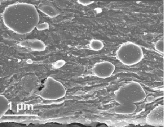
It is important in alloy development programmes to appreciate that graphite is generally more stable than cementite, but is usually not observed because cementite is kinetically favoured. However, spheroidisation heat treatments can be prolonged, and graphite formation has been observed in chromium-free steels containing a relatively large concentration of silicon (0.7 wt%), [278, 277]. Silicon has a very low solubility in cementite and hence promotes graphitisation.
The structure of the steel prior to spheroidisation can be problematic for large section hot-rolled bars, which develop networks of carbides along the austenite grain boundaries in the central regions which cool relatively slowly. These network-carbides are more difficult to anneal and the problem can be mitigated by cooling more rapidly from the hot-rolling temperature [279]. Alternatively, normalising the hot-rolled steel prior to the spheroidising heat treatment has also been reported to help mitigate carbide clusters in the final microstructure [280]. Repeat annealing with a second tempering treatment at a lower temperature is said to help break up the networks [281].
Steels for Aerospace Bearings
Special Requirements
Aircraft engines represent one of the most sophisticated of engineering technologies; it is not surprising that they have led the development of some quite elaborate steels. Bearings on engine shafts have to tolerate vibratory stresses, bending moments and high rotation speeds, for example, 25,000 revolutions per minute, elevated temperatures and aggressive lubrication10. The fracture of a bearing race can have serious consequences on the integrity of the engine [283].
The thrust to weight ratio has to be maximised in order to optimise fuel efficiency. One way of achieving this is to reduce the mass of bearings, as long as the steel used in their manufacture is able to bear the resulting increase in structural stresses [300]. Whereas in slowly rotating bearings it is the highly-stressed inner race which determines the fatigue life of the bearing, centrifugal forces accompanying high-speed rotation add to the applied loads; the contact stresses on the outer race can then reach some 2 GPa [301]. Aircraft bearings have outer to inner diameter ratios of about 1.1 so that they can be approximated as thin rings for the calculation of the hoop stress which is given by \( \approx \rho r^2 \omega^2 \) where \( \rho \) is the density, \( r \) the average ring radius and \( \omega \) the angular speed of the shaft in radians per second [300]. The distance travelled by a point on the bearing raceway per minute is of the order of 3000 m min−1, for a raceway circumference of 0.12 m.11 This typically leads to a centrifugal hoop stress in excess of 200 MPa.
It frequently is necessary to sustain combined radial and thrust loads; some illustrative data are listed in Table 9. Given these circumstances, the bearing inner ring is often press-fitted to the shaft in order to prevent relative rotation and consequent fretting or ordinary wear. This fitting adds to the hoop stresses on the ring; it is recommended that this component of the hoop stress should not exceed about 140 MPa [302].
| % of speed | % time | Thrust / N | Life / h | Maximum Hertz stress / MPa | |
|---|---|---|---|---|---|
| Inner ring | Outer ring | ||||
| 60 | 10 (idle) | 3114 | \( 203 \times 10^3 \) | 1048 | 1331 |
| 100 | 20 (take off) | 11121 | \( 4.3 \times 10^3 \) | 1572 | 1944 |
| 100 | 70 (cruise) | 6672 | \( 7.5 \times 10^3 \) | 1331 | 1855 |
Secondary Hardened Steels
One of the distinctions of steels destined for aerospace applications or arduous environments is that they retain their hardness at temperatures in the range 120–320°C [305, 304], Fig. 37. Strength at high temperatures can also be useful in temporarily maintaining bearing integrity in circumstances where lubrication fails or becomes marginal [307, 306]. Hardness values below 58 HRC are undesirable as the usual steels then suffer from 'brinelling', i.e., the formation of grooves on the raceways. Early attempts at appropriate steel design were based on low-alloy steels modified in order to increase their temper resistance by boosting the silicon or aluminium concentrations, and introducing molybdenum carbides; Crucible Steel's vacuum-melted alloy 52CB (Table 1) is an example of this with the composition also designed to eliminate retained austenite in order to maintain dimensional stability [33, 308]. However, the best elevated temperature performance was obtained from adaptations of richly-alloyed tool steels such as M50; some typical chemical compositions are listed in Table 8. The cleanliness of aerospace bearing steels is all important and it is well-known that the fatigue life is enhanced by double vacuum melting, i.e., vacuum induction melting and vacuum arc remelting [9]. In this latter process the material is made an electrode from which an arc is generated, which causes droplets of the metal to trickle through the vacuum and become purified. The molten metal is usually contained by a water-cooled mould and solid impurities have an opportunity to separate by flotation. The controlled solidification inherent in vacuum arc remelting results in a macroscopically uniform ingot with few solidification defects [133].
M50 is a high-hardenability steel (Fig. 34) quenched to produce a predominantly martensitic microstructure. It relies on molybdenum carbides for its hot hardness, and is the most common alloy for the manufacture of turbine engines. They can be particularly susceptible to decarburisation and hence must be protected during heat treatment. The steel is usually preheated to 500°C, held there and then heated to 800°C, followed by austenitisation at 1100°C for long enough to reach temperature. During this austenitisation, approximately 3–4 wt% of molybdenum-rich M2C, vanadium-rich MC and possibly chromium-rich M6C are not dissolved [309], Fig. 35. The steel is then quenched to 560°C and air-cooled, leading to a microstructure consisting of undissolved carbides, martensite and about 20–30% retained austenite. A sub-zero soak at about −70°C is used to reduce the retained austenite content. Secondary hardening is conducted by tempering at 540–550°C for 2 h followed by air-cooling to ambient temperature. Tests indicate that the sub-zero treatment does not significantly influence fatigue life [282], which mostly scales with the hardness. When the sub-zero treatment is omitted, the alloy might be subjected repeatedly to the 550°C tempering, with cooling to room temperature between the tempering treatments, in order to minimise the retained austenite content to less than 4% thus improving dimensional stability during service, and in order to enhance toughness [310]12.
The maximum temperature at which 52100 steel can be used continuously is about 160°C, whereas M50 is designed for temperatures as high as 310°C, as is apparent from the hot-hardness data presented in Fig. 37. The hardness is a key factor which limits the operating temperature; it is known even for ambient temperature operation that the contact fatigue life improves as the hardness is increased beyond 54 HRC [311], and M50 is usually through-hardened to at least 58 HRC [302]. It has been pointed out that even if the hardness remains satisfactory above 400°C, the oxidation resistance of M1, M2, M10 and M50 steels is marginal [312]. The temperature dependence of the hot-strength of a series of secondary-hardening bearing steels (M1, M50, Halmo, WB49) can be normalised as follows [313]:
which compares with the greater temperature dependence evident in the 52100 steel:
M50 is sometimes even used when the service temperature is less than 150°C because of its high rolling contact fatigue life [314], although tests done with p0=5.5 GPa at 66°C indicate that 52100 is significantly better in its ability to resist this kind of loading. Furthermore, the M series of steels are more difficult to grind and finish [312]. In general, 52100 is regarded to be superior for applications at relatively low temperatures.
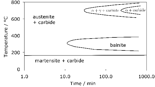
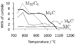 (b)
(b) 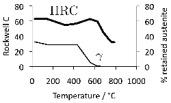
Toughness Enhanced Alloys
Most of the through-hardening steels used for aeroengine bearings are derivatives of tool steels and contain relatively large concentrations of solutes. They are not particularly ductile, with little elongation in tension tests, and a fracture toughness in the range 20–30 \( \text{MPa}\,\text{m}^{1/2} \) [287], Table 10. For this reason the M50 and 52100 steels are not used in tapered roller bearings which not only support greater loads but may require interference fits with shafts, a process which introduces tensile hoop stresses in the ring [1] and increases the chances of catastrophic raceway failure [316]. Thus, in the absence of the hoop stress, failure occurs by spalling, but otherwise the spalling is accompanied by ring failure [317]. The hoop stress \( \sigma_h \) due to press-fitting is given by [317]:
where \( \Delta \) is the expansion of the ring caused by the press fit, \( r_i \) and \( r_o \) represent the inner and outer ring radii, \( r \) is the radius to a particular location in the ring, and \( E \) is the Young's modulus. The stress is therefore a maximum at the inner radius. This stress decreases during the operation of the bearing as the ring expands due to centrifugal forces.
T1 (18-4-1) is tungsten-rich, used originally in Britain in the electroslag refined condition for gas turbine engine mainshaft bearings, hardened to some 60–65 HRC [318]. Following heat treatment, the composition of the matrix is not much different from that of M50 except that tungsten substitutes for molybdenum13. Its retained austenite content at about 10% following air-cooling is about a third that of M50, but has a much larger quantity of undissolved carbides (15%) in the form of M6C. Nevertheless, the general properties of T1 and M50 are very similar, dependent mostly on the matrix ductility and composition [319].
The large solute content of alloys such as M50 and T1 makes them susceptible to chemical segregation during manufacture. During freezing to an ingot, the regions to solidify last are enriched in carbon and substitutional solutes which have a strong affinity for carbon [315]. As a consequence, large eutectic primary-carbides form, which although they are reduced in size by mechanical working, the fragments remain coarse. The final material contains a bimodal distribution of particles, the finer ones precipitated during tempering and the coarse carbides which are remnants of the solidification process (Fig. 36). The latter influence the development of fatigue damage and are detrimental to formability which is important during the fabrication of bearing rings. One approach is to reduce the total content of carbides without compromising other properties [286].
An alternative method studied in the context of M50 steel is to refine the dispersions by ausforming [320], in which the steel is deformed in its metastable-austenitic state at relatively low temperatures around 600°C [321, 322, 1]. This requires the time-temperature transformation diagram of the steel to have a bay at the temperature concerned, between the high-temperature diffusional transformations such as pearlite, and the low temperature displacive transformations such as bainite. As can be seen from Fig. 14, steel 52100 steel is not suitable for ausforming whereas Fig. 34 shows the sluggish rate of transformation in M50 at the ausforming temperature. Extensive experiments [321, 322] prove that ausformed M50 shows a significant improvement in rolling contact fatigue life as a consequence of the fragmentation and refinement of large carbides. However, ausforming is not in general practicable or cost-effective [9] and can lead to other difficulties by introducing structural defects during the warm-deformation.
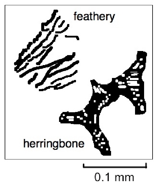
| Steel | \( K_{IC} \) / \( \text{MPa}\,\text{m}^{1/2} \) | \( \sigma_y \) / MPa | \( \sigma_u \) / MPa | % elongation | % reduction of area |
|---|---|---|---|---|---|
| M50 | 17–20 | 2110 | 2600 | 5 | 10 |
| M50 NiL | 55 | 1175 | 1387 | 15 | 74 |
| RBD | 25 | 1125 | 1410 | 16 | 52 |
| T1 (18-4-1) | 20–22 | 2100 | 2500 | < 1 |
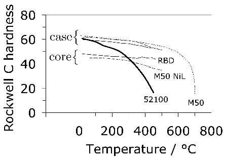
M50 NiL was developed in order to satisfy increasing demands for the structural integrity of aeroengine shaft bearings, as a derivative of M50 [325, 162]. With a composite microstructure in which the case-hardened surface is tenacious but the lower-carbon core is not, it is capable of supporting more arduous engine conditions than envisaged for M50. The core toughness is about 40–55 \( \text{MPa}\,\text{m}^{1/2} \) [324, 284] because the reduced carbon concentration leads to a better distribution of carbide particles, Fig. 38. The nickel is needed to stabilise the austenite [283]. Its hot-strength (Fig. 37) relies on secondary hardening with alloy carbides, mainly \( \text{M}_6\text{C} \), \( \text{M}_{23}\text{C}_6 \), and \( \text{MC} \). [326]. The last two of these carbides may remain partially undissolved during the austenitisation heat-treatment.
The relatively soft core does not have sufficient hardness to resist the required contact stresses, so it is fortunate that M50 NiL can be carburised readily in a process which is relatively insensitive to variations in the processing times and temperatures. The carburised region naturally has a larger fraction of carbides, and \( \text{M}_2\text{C} \) and possibly \( \text{M}_7\text{C}_3 \) are found in addition to the carbides present in the heat-treated core [326]. Case-hardening leads to a favourable compressive stress on the surface, which gives M50 NiL bearings a greater rolling contact fatigue life than those which are made from through-hardened M50. This state of stress in case-hardened structures also enhances the resistance to surface distress resulting from unintended metal-to-metal contact. Early attempts at making a carburisable version of M50 reduced the carbon concentration to about 0.35 wt% [327] but M50 NiL contains even less carbon in order to reduce the hardness of the core. The heat-treatment of case-carburised M50 NiL is similar to that of M50, and after multiple tempering the case contains only about 3% of retained austenite [314]. The carbides within the core of M50 NiL are less than 1 µm in size whereas they can be many tens of micrometres large in M50 [314].
The alloy designated RBD was developed in the U.K. for military purposes and is a carburising steel with a slightly higher carbon concentration than M50 NiL. In general, the carbide dispersions in M50 NiL are finer than RBD [284] and this gives the former a greater toughness. Both alloys are typically carburised in the range 840–950°C for periods of 4–30 h [163].
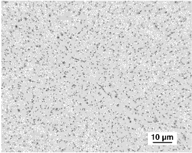 (b)
(b) 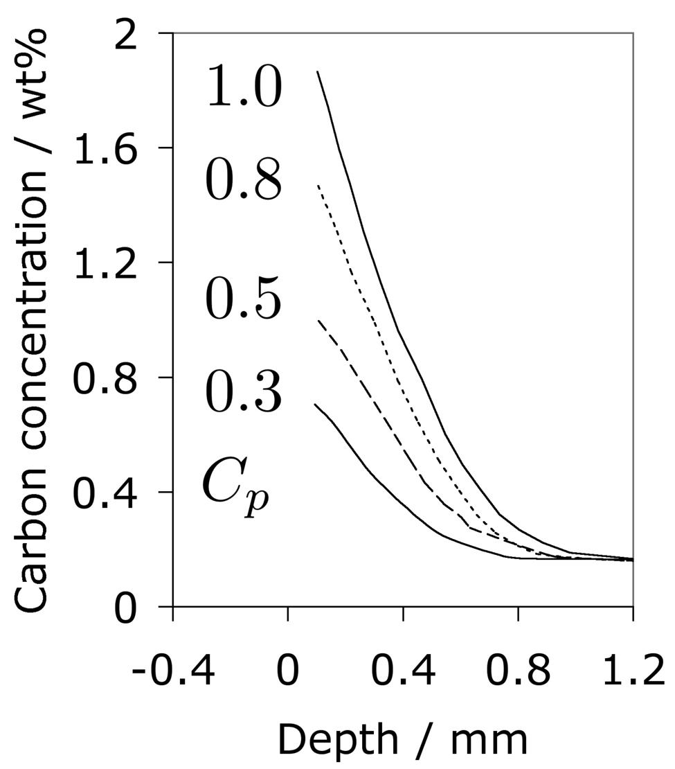
An alternative approach to obtaining a temperature capability of carburising steel is to retard the martensite tempering reaction, particularly with the addition of silicon [283]. It has long been known that silicon inhibits the precipitation of cementite; concentrations of about 2 wt% silicon can change a brittle, cementite-rich cast-iron into a ductile graphite-rich grey cast-iron [331]. In strong steels, the silicon is used to control the tempering of martensite [78, 332, 74, 76, 77, 333, 334]. Indeed, this is the basis of the successful alloy 300M used for aircraft undercarriages, containing about 1.6 wt.% Si; in this case the rate at which cementite precipitates from supersaturated martensite is significantly reduced when compared with a corresponding steel without the silicon [335]. The mechanism by which silicon retards the precipitation of cementite is that the driving force for precipitation is dramatically reduced when the cementite is forced to inherit the silicon present in the parent phase. Any retardation is therefore prominent for transformations such as martensite which occur at temperatures where atomic mobility is limited [336, 337]. The bearing steel CBS 600 (Table 8) has an exceptionally large silicon concentration which retards the tempering of martensite; this allows the core of a case-hardened bearing made from this material to have sufficient hardness for use up to 315°C [283].
Attempts have been made to use a combination of nitrogen and carbon to modify the surfaces of M50 and M50 NiL whilst in the ferritic state, to improve both the fatigue and lubricated-wear resistance, with tests done at large Hertz pressures (greater than 5 GPa) in order to test partial elastohydrodynamic conditions whereby wear becomes significant [338]. The diffusion/reaction process used results in two surface layers, the topmost consisting of a brittle compound with a layer underneath with a diffusion profile of nitrogen in solid solution. The former was found to be detrimental to properties and would need to be removed or minimised prior to service, but the latter led to an increase in surface hardness to values in excess of 66 HRC. It was found possible to enhance fatigue life at the large contact stress when the compound layer was appropriately controlled, and not surprisingly, the wear resistance of M50 NiL also improved significantly relative to the untreated steel. M50 had essentially identical wear resistance in both the treated and untreated states, and this observation was attributed to the large carbides in this alloy [338]. However, this may not be justified because M50 is in any case through hardened to some 60 HRC, which may be sufficient to resist wear. It remains to be demonstrated that the coarser carbides in M50 are important in resisting wear.
Nitrided M50 has been reported to reach hardness levels of 72 HRC and when subjected to rolling contact stress in excess of 5 GPa, cracking was observed on the edge of the rolling track [339]. This is because the perimeter of the contact zone is subjected to a tensile stress. This mechanism of cracking is also observed in hybrid bearings where the rolling element is made of a ceramic and subjected to large contact stresses [340]. Tensile stresses have also been used to explain modes other than those typical of mechanisms associated with shear stresses [341].
CBS 1000 has a similar design philosophy to M50 NiL, in that it is used in the case-hardened condition but with the core sufficiently strengthened using secondary hardening. It has a significantly lower concentration of chromium and vanadium (Table 1); both of these solutes are strong carbide formers and at the same time reduce the activity of carbon in austenite, so it is expected that a reduced concentration should permit carbon to penetrate to a relatively greater depth during carburising than M50 NiL. The general influence of chromium on case depth has been known for some time [342]. Fig. 39 compares the carbon concentration as a function of depth for M50 NiL and CBS 1000, carburised under identical conditions.
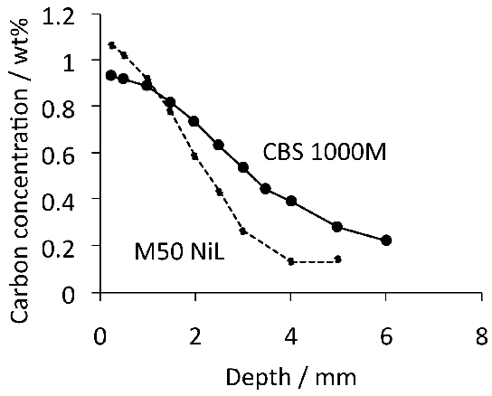
Duplex Hardening
Duplex hardening involves first the normal hardening heat treatment, followed by surface nitriding. The process can be used for secondary hardening steels such as M50 and M50 NiL because the nitriding typically has to be conducted at 500°C for 40–70 h and the intention is not to compromise the hardness achieved following the conventional hardening heat-treatment. The surface hardness that can be achieved following nitriding is in the range 1000–1250 HV; the hardness obviously declines as a function of depth, but can reach 0.2 mm using the salt nitriding process [344]. Large compressive residual stresses peaking at some 1300 MPa at about 0.1–1.3 mm below the surface can be achieved as a result of the nitriding process; in Fig. 40, the stress in the close proximity to the surface is influenced by the grinding operation. Some quite remarkable improvements in rolling contact fatigue life have been demonstrated in comparisons with the corresponding steels given just the conventional heat treatments [344]. Significant advantages have been observed when it comes to the operation of bearings in boundary lubrication or contaminated lubrication conditions; damage propagation rates are dramatically reduced [345].
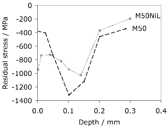
Thermal Properties
The heat generated inside the bearing raceway during the operation of a bearing is in the area influenced by the Hertzian contacts and depends on the local values of the friction coefficient and sliding speed. That which is not dissipated in lubricant serves to heat up the raceway [346]. The extent of this temperature rise depends also on the thermophysical properties of the steel, as listed in Table 11. This particular mechanism of heat generation is said to account for about a third of the loss due to the operation of the bearing. For an oil inlet temperature of 70°C, the increase in the raceway temperature within the contact zone can be some 150°C for operating conditions typical of aeroengine bearings. This leads to a reduction in the rolling contact fatigue resistance which is greater than that expected from the corresponding reduction in hot-hardness [346], presumably because thermal activation accelerates localised damage mechanisms involving microstructural change. One additional consequence of the sliding is that there are localised temperature and pressure spikes created in the lubricant which lead to a decrease in the lubricant film thickness [347] and hence enhance damage through asperity contact.
| Steel | Temperature (20°C) | Density \( (\text{kg}\,\text{m}^{-3}) \) | Specific heat \( (\text{J}\,\text{kg}^{-1}\,\text{K}^{-1}) \) | Thermal conductivity \( (\text{W}\,\text{m}^{-1}\,\text{K}^{-1}) \) |
|---|---|---|---|---|
| M50 | 20 | 7780 | 448.1 | 25.0 |
| 100 | 7759 | 476 | 26.9 | |
| 200 | 7730 | 512 | 28.2 | |
| 300 | 7700 | 550 | 28.7 | |
| 400 | 7667 | 591 | 28.6 | |
| M50NiL | 20 | 7850 | 436 | 19.3 |
| 100 | 7830 | 463 | 21.3 | |
| 200 | 7804 | 500 | 23.2 | |
| 300 | 7776 | 539 | 24.5 | |
| 400 | 7745 | 581 | 25.0 | |
| Cronidur 30 | 20 | 7660 | 455 | 17.0 |
| 100 | 7640 | 487 | 18.8 | |
| 200 | 7612 | 526 | 20.6 | |
| 300 | 7583 | 566 | 21.9 | |
| 400 | 7551 | 605 | 22.4 |
Corrosion Resistant Steels
Corrosion can play many roles in the operation of bearings. In ordinary bearings, it may manifest locally when components are stationary for long periods, or through contamination of various sorts. Corrosion is a particular issue for naval aircraft engine bearings where the corrosion rate of M50 is said to be unsatisfactory [296]. The consequences of corrosion reactions include the generation of hydrogen which penetrates the steel and does harm to its mechanical properties. The discussion of hydrogen is reserved for a later section.
Stainless steel bearings find applications in corrosive environments, such as those which might occur in the aircraft and paper industries, in food processing and in the manufacture of pumping systems. Chromium can make a steel stainless by forming a thin, coherent and electrically insulating film of chromium oxide on the surface exposed to air. The concentration of chromium in solid solution must exceed about 12 wt% for this film to regenerate when damaged. Molybdenum helps improve pitting corrosion resistance [348]. Steel 440C (Table 8) is based on this principle with 17 wt% chromium and 0.75 wt% molybdenum; the carbon concentration is about 1 wt% in order to ensure the hardness necessary for bearing applications, which is in the range 59–61 HRC [349]. Given the combination of carbon and chromium, the alloy contains coarse stringers of eutectic carbides after hot-deformation processing (Fig. 41), a mixture of \( \text{M}_7\text{C}_3 \) and \( \text{M}_{23}\text{C}_6 \), 10–30 µm in size [328, 350]. The variation in hardness as a function of austenitisation temperature is illustrated in Fig. 42.
It is emphasised that the rolling-contact fatigue performance of steels such as 440C is sensitive to the environment they are exposed to. It has been shown, for example, that the service life is reduced by more than an order of magnitude in the presence of high-pressure, moist CO2 contaminated with chloride [351]; surprisingly, the failure mechanism was apparently not different from the ordinary fatigue modes, i.e., no particular evidence was obtained for stress corrosion or hydrogen embrittlement phenomena. Therefore, the exact mechanism of accelerated fatigue is not established.
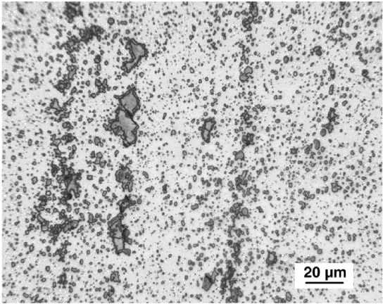
The question arises as to whether 17 wt% Cr is necessary for passivation since some of this will be tied up in the form of carbides, of which the coarse variety is in general detrimental to fatigue properties [1]. A variety containing only 0.7C-13Cr wt% martensitic steel (13Cr-SS, Table 8) avoids the eutectic carbides and maintains the corrosion resistance. Steel ES1 is a further development based on a combination of carbon and nitrogen, and with an even greater capacity to resist corrosion, partly because of the alloying with nitrogen [289, 350]. The bearing life is also said to be better with ES1 and this is consistent with the observation that coarse carbides in tool steels increase the rate of fatigue crack growth by initiating bursts of failure ahead of the crack tip [287]. Another steel which seems to be based on the same principles is HNCR; it is also a nitrogen-alloyed stainless steel and in the heat-treated condition has a hardness of 58 HRC and is claimed to have a better corrosion resistance than 440C [290].
A variant of 440C has been developed with reduced carbon and chromium concentrations in order to avoid the large carbides whilst maintaining the corrosion resistance; the hardness of this martensitic stainless steel '440 N-DUR' [288] is maintained at 60 HRC by adding about 0.1 wt% nitrogen. This concentration of nitrogen can be achieved without using pressurised casting techniques. One application of this alloy is in the computer industry where the absence of coarse carbides leads to a better surface finish and a reduced level of noise during operation. Steels such as 440C, 440 N-DUR and XD15N can be induction hardened [352].
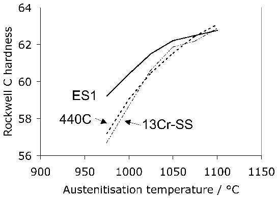
Cronidur 30 is a high-nitrogen martensitic steel generally used in the through-hardened condition, with outstanding corrosion resistance and a fine, relatively homogeneous microstructure, particularly in the secondary hardened condition [353, 354]; N360 is an almost identical steel produced by a different manufacturer [292]. Like M50 NiL, the steel does not suffer from the presence of large carbide particles because of its low carbon concentration. In contrast, M50 and 440C (Fig. 41) both can exhibit cementite particles as large as 60 µm in size [355]. The microstructure is based on a dispersion of fine carbonitrides which are relatively stable, thus permitting prolonged use at temperatures up to 200°C, although the accumulation of damage at this temperature is not particularly different from that of M50 [291]; it has been shown that the alloy can be used in applications up to 320°C [357, 356]. Its retained austenite content can be as high as 15%, a value which decreases during service to about 8% in the most stressed regions [291]. In its heat-treated condition, the steel has a hardness of about 58 HRC, σy=1850 MPa, σu=2150 MPa, εT=3%, and a fracture toughness of \( \approx 20\,\text{MPa}\,\text{m}^{1/2} \)[358]. The alloy is found to have a much greater rolling contact fatigue life, both in full and boundary lubrication conditions, than for example M50 steel [355], Fig. 43.
As pointed out above, Cronidur 30 is designed for through-hardening; however, the alloy has been successful in engineering applications where the surface is induction hardened whilst the core is maintained relatively soft (38 HRC) [359]. It is necessary, in order to achieve a surface hardness of 60 HRC, to heat-treat the alloy prior to induction hardening so that the coarse chromium-rich carbides are reprecipitated in a finer state whence they can dissolve rapidly during induction heating. Otherwise, the required surface hardness is not achieved. In this surface-hardened condition, the core toughness is some \( \approx 70\,\text{MPa}\,\text{m}^{1/2} \)., and a compressive stress is induced in the surface to a depth of about 1.5 mm. Given the intrinsic corrosion resistance of the alloy, this represents an impressive set of properties.
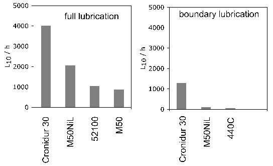
Nitrogen has been known for some time to enhance the pitting corrosion resistance of stainless steels [361, 360]; although the mechanism must depend on the details of the corrosive environment, it is thought that the nitrogen helps form inhibiting compounds at the pit sites [362]. To achieve the high nitrogen concentration, Cronidur 30 is produced using a pressurised electroslag remelting process in which electrodes of the appropriate composition are remelted under a pressure of up to 42 bars, with silicon nitride added to adjust the nitrogen concentration. The large chromium concentration aids the absorption of nitrogen by reducing its activity in the steel [363].
Another steel somewhat similar to Cronidur 30 and N360, but with a lower nitrogen concentration because it is not produced using the pressurised electroslag process, is XD15NW (Table 8). It is stainless, has excellent salt-spray corrosion resistance and, like Cronidur 30, a much more uniform microstructure when compared with alloys such as 440C, as illustrated in Fig. 44. Table 12 shows how some of the specialist alloys fare in terms of typical property requirements; detailed information can be found in [295].
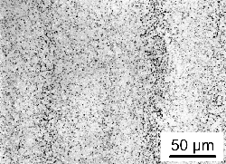 (b)
(b) 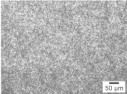
| Type | Designation | Corrosion | Fatigue | Toughness | Wear |
|---|---|---|---|---|---|
| Through hardened | Cronidur 30 | 1 | 1 | 3 | 2 |
| XD15NW | 1 | 1 | 1 | 3 | |
| Case hardened | Pyrowear 675 | 2 | 3 | 1 | 1 |
| CSS42L | 2 | 2 | 2 | 1 | |
| Nitrided | 32CDV13 | 3 | 2 | 1 | 1 |
Cryogenic Conditions
Cryogenic bearings are used in the NASA space shuttle and Ariane rocket engines to pump liquid hydrogen fuel. The bearing raceways are made of steel, the rolling elements from silicon nitride, and the cage is made of PTFE-impregnated glass fabric; the PTFE also provides some dry lubricant between the rolling elements and raceway [294]. The martensitic stainless steel 440C has in the past been used for the raceways because it is stainless and strong (Table 13). However, the toughness is compromised by the presence of coarse carbides (Fig. 41) and Cronidur 30 or N360 is now the material of choice because of its greater toughness and superior corrosion resistance, although it should be emphasised that the reported corrosion tests are in sulphuric acid or sodium chloride solutions so their significance with respect to cryogenic pumps is not clear. When used in the induction-hardened condition, its core fracture toughness is said to be in excess of \(50\,\text{MPa}\,\text{m}^{1/2} \).
An experimental alloy designated NASA1 (Table 8) based on a low-carbon, secondary-hardening system that avoids any carbides which are undissolved at the austenitisation temperature, has a final hardness of some 60 HRC, toughness of \( 47\,\text{MPa}\,\text{m}^{1/2} \) and sufficient stress corrosion crack resistance. It has been designed for the pumps in the space shuttle [297], but there do not appear to be any data reported on rolling contact fatigue or performance at cryogenic temperatures. Impressive rolling contact data have been reported for a variant (Ferrium C69) [298, 364]. Work has also been done to utilise a modified version of Ferrium C69 in a surface-hardened condition [365].
| Alloy | \( T \) / K | \( \sigma_y \) / MPa | \( \sigma_u \) / MPa | Elongation / % | Charpy / J | ||
|---|---|---|---|---|---|---|---|
| \( - \) | \( + \) | \( - \) | \( + \) | ||||
| 440C, 58 HRC | Ambient | 2027 | 1273 | 2516 | 1748 | 0.2 | 19 |
| 440C, 58 HRC | 78 | 1127 | 3 | ||||
| Cronidur 30, 58 HRC | Ambient | 1864 | 1862 | 2610 | 2169 | 4 | 120 |
| Cronidur 30, 58 HRC | 78 | 20 | |||||
| Cronidur 30, 34 HRC | 78 | 1346 | 1581 | 4 | |||
Powder Metallurgical Steels
Steels produced by a powder metallurgical route can be more richly alloyed than those which are cast, since chemical segregation cannot in the former case extend over distances larger than the powder size. Alloys produced by this more expensive method are usually chosen when a hardness greater than 60 HRC is required, and when the properties can be maintained at higher temperatures and loads. Abrasion resistance, operation in contaminated or corrosive environments, and the ability to resist shock loading are other possible distinguishing characteristics which can be achieved by manufacturing bearing rings using powder metallurgy [366].
Hybrid bearings in which the rolling elements are made from silicon nitride (Si3N4) make them harder than steel balls; the elastic modulus of silicon nitride is also greater, leading to larger contact stresses on steel raceways for a given load. It follows that to achieve the same load-bearing capacity, the steel raceways must have a hardness greater than can be achieved using 52100 steel. M62 (REX20) and CRU80 (Table 8) are two examples of alloys produced using powder metallurgy, both extremely rich in carbon. They are made using gas atomisation, hot isostatic pressing and forging, resulting in a fully dense alloy at the end of the process. CRU80 has a large chromium concentration for improved corrosion resistance and was developed as a potential replacement for 440C [285]. Both are martensitic with finely dispersed alloy-carbides which enhance the wear resistance. After oil quenching from temperatures in the range 1150–1215°C, they are repeatedly tempered at 540–560°C for two hours to give a microstructure containing about 20–23 vol.% of carbides, some of which are generated by secondary hardening [366, 367]. An intermediate cryogenic treatment may be included to control the quantity of retained austenite to about 5 vol.%.
REX20 is an air-melted powder metallurgical version of M62 tool steel, and CRU20 is simply the vacuum induction melted variant with a substantially lower sulphur content, which has been shown to have a rolling contact fatigue resistance comparable to that of silicon nitride [368]. It can achieve hardness in the range 66–67 HRC giving it a static stress bearing capacity of 3790–4100 MPa [367]. When applied in hybrid bearings, the fatigue life can be some six times greater than an identically loaded bearing made from 52100 steel [369]; indeed, the life may be determined by the failure of the balls through sintering defects rather than of the raceway.
CRU80 can achieve a hardness in the range 58–62 HRC depending on heat treatment which compares with 58 HRC for 440C wrought-steel, but can be much more corrosion resistant; it has almost twice the carbide content of 440C and hence a better adhesive or mildly-abrasive wear resistance [366].
Conventional cast and wrought bearing steels such as M50 and 440C have been compared against their powder processed variants [370]. The latter do not compete on a cost basis because the fatigue is found to be comparable to that of cast alloys, in spite of the more homogeneous and fine microstructure. It is possible that this could be explained by the much greater oxygen concentration (≈ 80 ppmw) of the powder processed alloys. On the other hand, the absence of coarse carbides which originate in long-range chemical segregation results in better surface finish and reduced probability of early failures [370]. Another advantage is that the amount of waste associated with the production of rings by powder metallurgy is reduced relative to the wrought product [371]. The damage mechanism, for example the structural changes in the sub-surface layers (carbide decay and White matter), are essentially identical in roller bearing rings manufactured using powder metallurgy [373, 372]. However, there may be residual porosity from the sintering process and that can be the predominant source for the initiation of butterflies rather than the non-metallic inclusions [373], consistent with early work indicating that voids are more potent sites for butterfly formation [374].
Casting and Melting Practice, Segregation and Inclusions
Melting and Casting
Non-metallic inclusions are of particular importance in the context of steels for bearings. Refining and melting practice has to be adapted to deal with the so-called endogenous particles which are generated during the deoxidation process, and exogenous inclusions arising from slag entrapment, contamination from refractory materials and oxidation in air when the molten steel is poured without isolation from the environment.
Experiments using radioactive markers indicate that some 70% of the oxide inclusions originate from the vacuum degassing and deoxidation using aluminium, the remainder coming from the furnace slag or reactions within the mould [375, 376]. Aluminium-free deoxidation is usually based on silicon with the resulting silica absorbed into a lime-based slag; the process then includes vacuum treatment to reduce any fine SiO2 by the carbon present in the melt [10]. This last step is not possible with alumina given the strong affinity between aluminium and oxygen. There has been an initial study on deoxidation using an Al-Mg alloy, which at the right chemical composition changes the inclusion from alumina to an Al2O3.MgO spinel [377]. The spinel particles are reported to be much finer than corresponding alumina particles.
The history of the manufacture of bearing steels has been summarised by Glasgal [378] and is illustrated schematically in Fig. 45. When bearing steels were made using air melting, the emphasis was on the type of refractory used, i.e., whether it was acidic or basic [379, 3]. The term 'basic' refers to refractories based on magnesite (MgO) or lime (CaO) as opposed to silica which is 'acidic'; slags are similarly classified. A basic slag is more conducive to the removal of impurities such as sulphur or phosphorus from the high-carbon steel melts typical in the bearings industry [380].
The introduction of ladle metallurgy led to a step change in the control of unwanted solutes and phases. Melting processes (open-hearth, electric arc, basic oxygen furnace) became less important to cleanliness because the inclusion content could be greatly reduced by ladle-treatment and the careful pouring and protection of molten steel [383, 382].
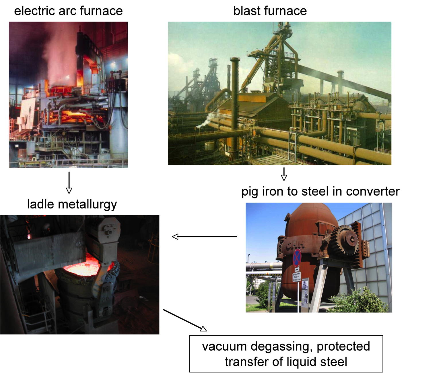
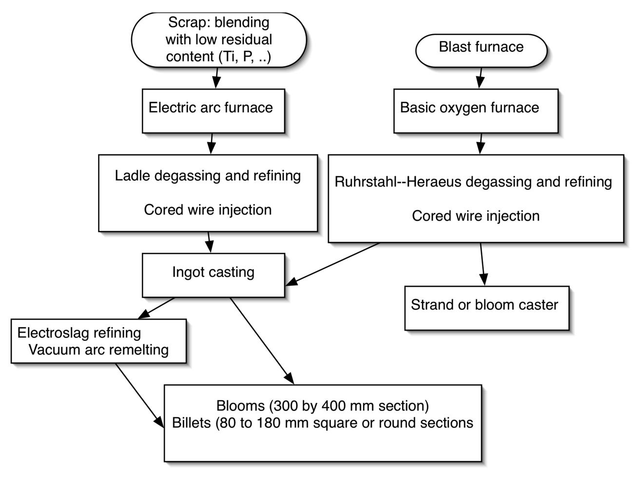
Segregation
Segregation occurs because it is impractical to cool the melt at a rate which maintains equilibrium until fully solidified. Solidification Enriched liquid is separated from the original solid over large distances. Macroscopic 'V'-segregates in continuously cast steel occur when tensile stresses develop due to differences in thermal gradients across the mushy zone, causing segregated liquid to percolate into voids [145].
Microsegregation is confined to the dimensions of dendrite arm spacings (dp and ds), related to solidification conditions as follows [399]:
where \( \dot{T} \) is the cooling rate and \( \Delta T \) the freezing range. In bearing steels like 52100, segregation is driven by the inability of chromium to move rapidly within the solid during freezing [401].
| Property | Columnar | Equiaxed | V-segregate |
|---|---|---|---|
| Percentage area of sulphides | 0.08 | 0.04 | 0.10 |
| Average sulphide size / µm2 | 6.5 | 41.5 | 68.5 |
| Cr in sulphides / wt% | 10 | 7 | 4 |
| Percentage area of carbides | ∼ 0.05 | 0.44 | — |

The problem of centre-line segregation can be mitigated by soft reduction, where partially solidified strands are mechanically deformed to compensate for solidification shrinkage [430, 432]. Homogenisation time \( t_h \) in hours and absolute temperature \( T_h \) are related by [433]:
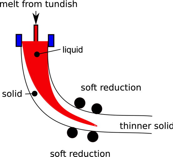 (b)
(b) 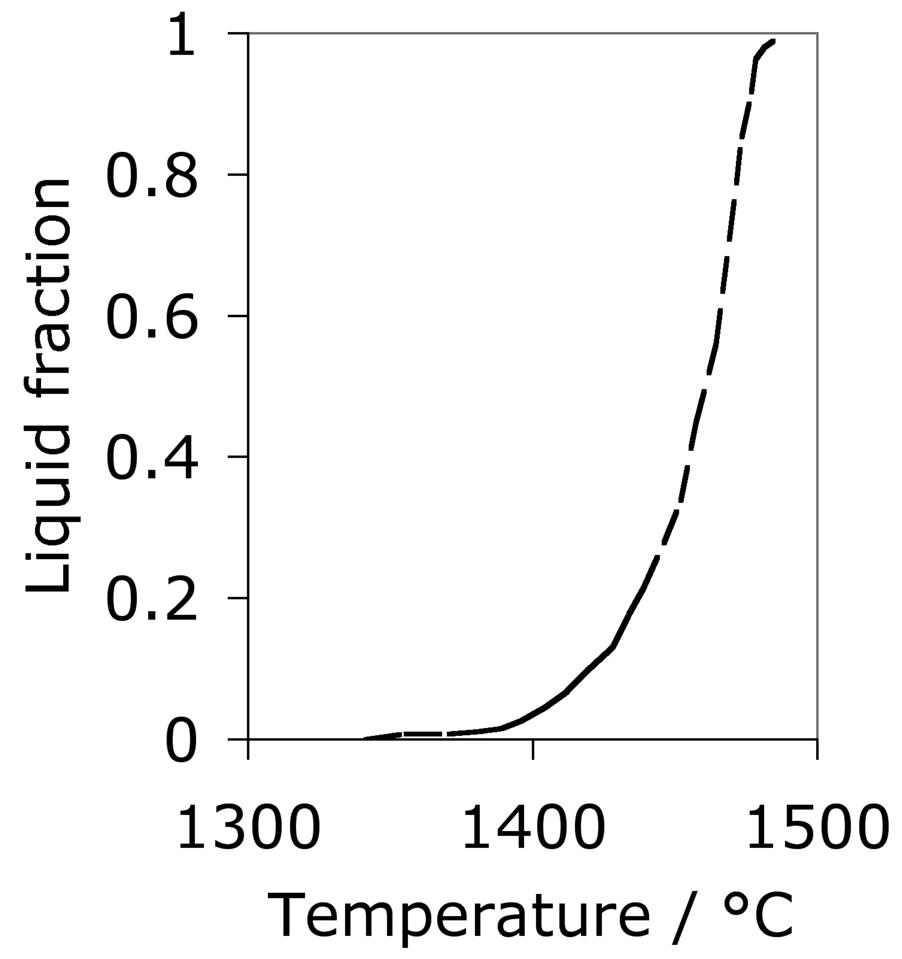
A recent innovation involves the application of electrical pulses to the semi-solid ingots as a means to stimulate nucleation at the free surface of the melt where the electrical current apparently focusses. The nucleated particles then sink into the underlying liquid, thus changing the coarse solidification microstructure from one dominated by the directional growth of dendrites from the mould surface, into an equiaxed set of grains originating at dendrite fragments dispersed in the liquid [439]. The electropulsing involved peak currents of about 2000 A at a frequency of 200 Hz, for a period of about 60 s (the precise details have not been revealed). The columnar to equiaxed transition induced by electropulsing led to a more homogeneous structure and uniform composition in a 52100 steel. It is argued that the heating associated with the current tends to retard the nucleation of dendrites at heterogeneities such as the mould surface, and at the same time reduces their growth rate, thus allowing the particles formed at the surface to make a greater contribution [440]. However, it is not clear why nucleation at the liquid surface is not similarly retarded by the Joule heating.
There has been limited work on fabrication of 52100 type bearing steel billets using the spray deposition technique [442, 441]. This method avoids long-range chemical segregation of the type typical with ingot casting since the droplets are partially solidified before they deposit and then rapidly complete solidification, but does not produce a fully dense material even when tubes are spray formed on to austenitic steel bars [443]. The pores are large, typically some 100 µm and with irregular shapes; the microstructural homogeneity can be compromised if there are variations in the cooling rate between the centre and edges of the billet [444]. The distribution of porosity is not uniform (Fig. 49), increasing towards the surface of the billet; the surface is therefore peeled prior to hot-rolling [445]. A comparison of shape changes caused by heat treatment indicates that the more homogeneous spray formed samples exhibit smaller distortion than corresponding samples from continuously cast alloys with greater variations in chemical composition [446]. Anything that favours a uniform phase transformation temperature as a function of position must lead to lower residual stresses, although the scale over which segregation must be reduced is not yet known in order to take advantage of homogeneity.
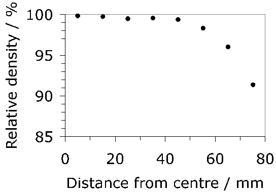
Hot-rolling after deposition does close some of the porosity but there is only cursory evidence that the inclusion content of the deposited material is less than the steel produced by conventional processing, in the form of low-magnification micrographs. A proper inclusion characterisation similar to the methods used for conventional bearing steels is called for. Rolling contact fatigue experiments have yet to be reported. It is surprising that the concentration of impurities such as oxygen have not been reported for the spray-formed billets, given the enormous amount of work in the literature on the critical role of oxides in bearing steels. The spray forming is carried out in an inert environment, but it is not clear how inert this is, and whether the final oxygen concentration depends on the level present in the feed stock. Similar comments apply to 52100 type steel produced using powder metallurgy [447], where the uniformity of the structure is said to be better than in the cast state; it is said that although the oxygen concentration in this case is much higher than in the cast 52100, the oxides are said to be fine and well-dispersed [448]. The 52100 has to be modified with reduced silicon and manganese concentrations down to 1500–2000 ppmw by annealing the powder in hydrogen.
Some very high carbon and solute-rich alloys, such as M62 or CRU80 (Table 8) can only be produced using powder metallurgy in order to obtain any semblance of homogeneity.
A modification of 52100 involving a reduction in the carbon and chromium concentrations and higher manganese content has been investigated with the specific aim of reducing the tendency for centreline carbide stringers in continuously cast blooms and billets from relatively small casters; it has been designated 80CrMn4 (Table 1). It seems to mimic successfully the important mechanical and thermal processing characteristics of 52100. However, there is no further open literature on this alloy since the original publication [37].
In its ingot-cast form, M1 solidifies in the form of cellular dendrites which are surrounded by large carbides of the MC, M2C and M6C variety [151]. Although these cellular networks of carbides are broken up by subsequent deformation, they spread out to form the infamous banding. Gas atomisation and consolidation of the resulting powders eliminates this banding. Laser glazing, which involves the melting and rapid re-solidification of the surface to a depth of about 100 µm is effective in eliminating both banding and coarse carbides, whilst at the same time, inducing a compressive stress into the surface. It is noted that M1 is not a usual bearing steel but has historically been considered for aeroengine applications [449].
Processing for Cleanliness
The enormous success of vacuum processing has set the standard for clean bearing-steels. In vacuum induction melting (VIM), the cold metal is remelted in a furnace lined with high-purity refractory, and the melt is maintained under a vacuum which encourages the removal of gaseous impurities. A further degree of quality is achieved by vacuum arc remelting (VAR) where the ingot produced in the VIM furnace is made a consumable electrode which is remelted by striking a direct current arc under vacuum. Droplets of liquid drop from the electrode into a water-cooled mould. In the process, some oxides and nitrides dissociate and are pumped away, whereas others become separated by flotation. Vacuum processing does not on the whole change the character of inclusions but does reduce the inclusion content [450].
Vacuum melted steel is in general more susceptible to austenite grain growth than that which has been melted in air [379, 451], largely because the number density of inclusions, and the total surface area of inclusions per unit volume are dramatically reduced [452]. Coarse austenite grains make bearing steels more susceptible to the phenomenon of overheating, in which manganese sulphides liquate at the grain surfaces during heat-treatment [454, 453]. Notwithstanding these difficulties, vacuum melted samples with their lower inclusion content perform better in rolling-contact fatigue tests [451], particularly because of a reduced oxide content [455]. The concentration of oxygen in the steel decreases as the alloy is treated at higher vacuums, Fig. 50 [456]. There is some evidence that electroslag refined steels outperform other casting techniques in producing steels which are less susceptible to fatigue failure at the same oxygen concentration, Fig. 97 [115]. This is because the distribution of inclusion sizes is shifted towards lower mean values in the electroslag process [457]. Even better results can be obtained by ladle refining using a highly basic slag with a low FeO content, followed by vacuum degassing using the Ruhrstahl-Heraeus process in which steel is circulated between the degassing unit and the transport ladle, and finally the repetition of the ladle refining to remove large inclusions [457]. Advanced processing of this kind has essentially meant that continuous and ingot casting lead to similar qualities of bearing steels [458, 146, 394].
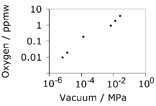
Electroslag refining as an additional melt-treatment leads to improvements beyond that achievable from vacuum melting alone; it is known to lead to a reduction in the silicon and more significantly, the phosphorus concentration of the steel [459]. Electroslag remelting sometimes results in better fatigue resistance than vacuum degassed steel, primarily by reducing the incidence of low-life failures [104]. Electroslag refining leaves the steel with a large oxygen concentration, many tens of ppmw [460]. This emphasises a general point [378] that it is not simply a reduction in oxygen content that matters, but a reduction in the size of large inclusions and for a given concentration; a homogeneous distribution of inclusions must also be advantageous. The remelting provides an additional opportunity for large inclusions to be floated off. The process can also be conducted under pressure when nitrogen is an alloying element.
Low levels of critical impurities can apparently be achieved without the vacuum or electroslag remelting, by argon stirring, induction stirring and vacuum degassing of the ladle [461]. Success in this context is classified by the sum of oxygen, titanium and sulphur being less than 80 ppmw. The use of ceramic filters to remove large non-metallic inclusions remains a contender in the search for cleaner steels [378], although the subject does not seem to have made much progress since 1988.
Anisotropy
Many bearing steels are ingot cast and the pipe created by the contraction of the liquid on solidification is removed prior to processing. Inadequate cropping of this pipe can lead to the entrapment of very large oxide inclusions, several mm in dimension, in the final processed product [462], Fig. 51. It has been known for a long time that the steel is dirtiest along the axis of the ingot so that rolling contact fatigue improves with distance away from that axis [463].
A further indication of anisotropy in forged samples made from ingots is the fact that fatigue performance is optimum when the angle that the forging direction makes with the rolling contact surface is zero; a large angle in contrast, favours the early onset of damage [465, 64, 463, 464, 3]. Some of this anisotropy, often referred to as 'grain flow orientation', is related to the alignment of chemical segregation bands along the primary deformation direction, which may or may not at the same time be associated with excess preponderance of carbides (see for example, Fig. 6 of [465]), and of inclusions depending on the cleanliness of the steel. The bands are known to be favoured crack propagation directions depending on the nature of the stress that the steel is subjected to [467, 466]. Segregated 'carbide streaks' and large carbides are known to be damaging in rolling contact fatigue [64]. There is clear evidence that strings of non-metallic particles aligned normal to the contact surface are much more harmful than those parallel to that surface [468]; the Charpy toughness is also sensitive to the orientation relative to the grain flow [469]. Since the occurrence of large carbides is associated with chemical segregation, the problem becomes more severe when the final size of the bar stock is large, since the mechanical reduction from ingot to the bar is then smaller. It is well-established that even in modern clean steels, larger plastic reductions during the manufacture of bar lead to better fatigue properties because the inclusions are broken into finer particles by the deformation [390].
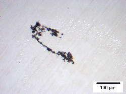
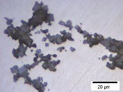
Aluminium Deoxidation
Aluminium has a strong affinity for oxygen and hence is added to bearing-steel melts as a deoxidiser. Most of the added Al combines as Al2O3 and floats off into the slag assuming that the time available is sufficient for this process. An excessive use of aluminium can reduce the viscosity of the slag, making the electrical arc of the furnace less stable. In practice, particles of alumina greater than about 20 µm tend to be removed into the slag. Any aluminium left in the solidified steel is mostly in the form of alumina particles which can be detrimental to the mechanical properties of the bearing. Typical concentrations of aluminium in the final steel are in the range 0.02–0.04 wt% [456]. For reasons which have not been discussed, ball-bearing steels which are not deoxidised using aluminium have better workability and surface quality following cutting or grinding operations [470].
Calcium Treatment
Large calcium-containing inclusions are detrimental to the fatigue properties of bearing steels [471]. Calcium-silicon alloys are added to steel for a variety of reasons. Solid alumina inclusions can block casting nozzles, but this problem is reduced by rapid reaction with calcium to form a liquid calcium aluminate [472]. There is, however, a tendency to form a CaO-rich glaze on the ladle used in secondary steelmaking, which can in principle introduce calcium-containing non-metallic inclusions in the melt [389]. The growth rates, at a given oxygen concentration in liquid iron, of calcium and magnesium oxides are significantly smaller than of alumina [473]; this could imply that these oxides are less readily extracted from the steel into the slag by flotation.
Calcium also has a strong affinity for sulphur and hence helps reduce the quantity of sulphides which may influence fatigue behaviour, although some data indicate that the fatigue resistance of 52100 type steel is insensitive to quite large variations in the sulphur concentration [138, 474]. For α-MnS, the expansion coefficient is \( 16.3 \times 10^{-6} \text{ K}^{-1} \) over the range 225–591 °C and \( 17.4 \times 10^{-6} \text{ K}^{-1} \) between 591–928 °C [475]. These values are somewhat smaller than the expansivity of austenite, so that significant stresses may not develop around the sulphide during cooling from elevated temperatures. The expansion coefficient of austenite in 52100 type steel has been measured to be \( 22 \times 10^{-6} \text{ K}^{-1} \). [476].
Types of Inclusions
Inclusions, some of which are listed in Table 15, are problematic in bearing steels for a variety of reasons:
- They have different thermal expansion coefficients from the matrix, in most cases less than that of austenite. As a consequence of cooling to ambient temperatures, tensile and compressive residual stresses develop parallel and normal to the inclusion-matrix interface. The tensile stress aids in the nucleation of damage. In cases where the thermal expansivity is comparable or somewhat greater than that of the steel, the distribution of residual stresses is not harmful in itself, but may lead to the detachment of the inclusion from the matrix. A free surface of this kind is more susceptible to the formation of a rolling contact fatigue cracking [477] than one in which a compressive stress exists normal to the inclusion-matrix interface. This is because defects such as intrusions and extrusions can form more readily at the free surface, and may explain why attempts to exploit sulphides to improve fatigue performance have not been convincing [138].
- The inclusions may be brittle, and the resulting cracks concentrate stress and hence may propagate into the steel. Even the simple presence of an uncracked inclusion introduces a mechanical heterogeneity which locally changes the distribution of stress [478]. In such circumstances, the depth at which the maximum damage is expected will not necessarily coincide with that calculated from the Hertzian loading of a mechanically homogeneous steel.
- Almost all of the common non-metallic inclusions have weak interfaces with the steel. Strain incompatibilities during deformation processing of the steel can then lead to the formation of cavities localised at the inclusion interface along the direction of the principle plastic strain. Alumina and calcium aluminates have a much greater yield strength than the steel at the deformation temperature and hence are susceptible to void formation. In rolling contact fatigue tests conducted at contact pressures in excess of 5 GPa, they show a reduced life relative to the silica inclusions which deform with the matrix [479]. Inclusions with more than about 20 wt% of CaO retain their globular cast-shape into the final product and are particularly harmful to the mechanical properties [480]. Alumina inclusions coated with silica are less associated with voids; furthermore, the rolling contact fatigue life improves dramatically if the voids around alumina particles are closed using hot isostatic-pressing prior to fatigue [481]. Debonding can occur during the course of fatigue. Alumina inclusions have been shown to detach from the matrix during loading, thus concentrating stress in the surrounding matrix; in contrast, titanium carbonitride particles are apparently strongly connected to the matrix and hence fracture by cleavage, leading to a different mechanism of crack initiation, Fig. 52 [482, 483].
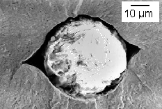
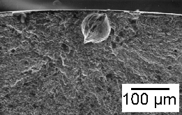
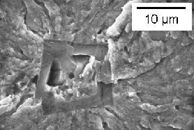
Studies have indicated that in modern steels, it is the titanium nitrides and carbonitrides which are most harmful to rolling contact fatigue, followed by oxides (particularly the globular particles which are spinels of calcium and aluminium oxides) and sulphides [128, 471]. Titanium carbonitrides have sharp corners, remain strongly bonded to the matrix and hence crack eventually, leading to a sharp wedge which propagates [484]. This is not the case for alumina particles which debond and hence do not crack. Sulphide coatings on oxides reduce the potency of the oxides to induce damage [485, 128], presumably because the sulphide is able to hot-deform and hence accommodate the incompatibility of plastic strain between the oxide and steel. However, such conclusions cannot be generic and must depend on the method of testing, whether in push-pull or rolling contact loading (section 21.2.3), the detailed chemical composition and processing of the steel concerned. For example, Ti(C,N) of identical size and location as oxides do not seem to induce the formation of butterflies [127].
| Inclusion | Shape | Hardness / HV30 | \( e_T \) / \( 10^{-6} \text{ K}^{-1} \) | Stress | Modulus / GPa | Type |
|---|---|---|---|---|---|---|
| 52100 Steel | – | 750 | 12.5 | – | 210 | – |
| MnS, CaS | Streaky | 150–170 | 18.1 | Low | 147 | A |
| \( \text{Al}_2\text{O}_3 \) | Aggregates | \( \approx 2200 \) | 8.0 | Tensile | 387 | B |
| Ca aluminates | Globular | 900–2500 | 6.5–10.0 | Tensile | 113–350 | B, D |
| \( \text{CaO}\cdot 6\text{Al}_2\text{O}_3 \) | – | – | 8.8 | – | – | – |
| \( \text{CaO}\cdot 2\text{Al}_2\text{O}_3 \) | – | – | 5.0 | – | – | – |
| \( \text{MnO-SiO}_2 \) | Oblong | \( > 1100 \) | 5.0 | Tensile | 73 | C |
| \( \text{TiC} \) | Sharp cuboids | \( \approx 3000 \) | 9.4 | Tensile | 320 | T |
Toughness
There is little doubt that when it comes to hardened, high-carbon steels containing proeutectoid carbides, the fracture toughness is determined by those particles either promoting void formation or initiating cleavage cracks. A large class of such alloys has more or less the same, relatively low level of toughness ( \(\approx 20 \text{ MPa m}^{1/2} \() once the hardness exceeds about 50 HRC, whereas for lower strength alloys the toughness increases sharply as the hardness (carbon concentration) is reduced [488]. Non-metallic inclusions, dissolved hydrogen and factors such as the austenite grain size can also influence the brittleness of badly processed bearing steels.
Fracture Toughness
The fracture toughness in mode I loading for hardened 52100 type steels tend to have values in the range 15–20 \(\text{ MPa m}^{1/2} \), the lower values corresponding to larger carbon concentration within the steel [60, 489], Fig. 53. It is possible that some of the observed scatter is due to a factor which has received little attention, anisotropy [490], given that the steels such as M50 and 52100 are deformed into their final shapes and hence will have a distribution in size and shape of inclusions which is not orientation independent.
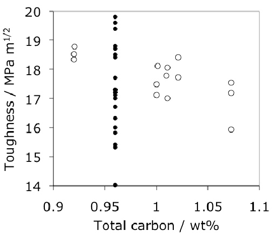
Phosphorus is a particular concern in the toughness of strong steels and bearing alloys are no exception [492, 491]. It is an element that is difficult to remove during steelmaking because it is noble with respect to iron during oxygen blowing, so the actual concentration in bearing steels is generally larger than that indicated in Table 3. Phosphorus, along with antimony, tin and arsenic have a potent influence in embrittling the austenite grain boundaries, a phenomenon often expressed empirically using a Bruscato factor ( \(\overline{X} \)) [493, 494] in order to highlight the relative potency of a variety of tramp elements where:
The common bearing steels often show smooth, intergranular fracture with respect to the austenite grain surfaces, attributed to phosphorus-induced embrittlement [496, 495, 489]. Auger spectroscopy has demonstrated phosphorus segregation to the fracture surface, when tensile specimens of 52100 type steel were broken in vacuum [497]. Since phosphorus is difficult to remove, its influence can be reduced by adding a small concentration of molybdenum ( \(\approx 0.25 \( wt%) [499, 500, 501, 498]. It was believed at one time that molybdenum scavenges phosphorus, but experiments have failed to confirm this mechanism [502].
It is interesting that the addition of 0.22 wt% of molybdenum to 52100 steel increases the ultimate tensile strength in the quenched and tempered state from about 2150 to 2450 MPa, even though the proof strength decreases from 1500 to 1400 MPa [29]. Since the steel without molybdenum has negligible ductility, it may be assumed that the higher ultimate strength is because of the greater plasticity of the molybdenum variant, although the original work [29] did not report these details. Any increase in ductility would be consistent with the suppression of embrittlement of the austenite grain surfaces. The original work on the molybdenum modified 52100 was on a steel containing 0.0075 wt% phosphorus and 0.25 wt% molybdenum; they all outperformed Mo-free 52100 in toughness and in rolling contact fatigue performance [28]. Phosphorus may also embrittle by accelerating the formation of cementite at austenite grain surfaces during heat treatment in the γ+θ phase field, possibly because it is incorporated in the growing cementite [503].
The levels of toughness encountered in the best of the hardened 52100 type steels are not enough to cope with severe static or dynamic structural loads, such as those encountered by hub bearings in the automotive industries. As shown in Fig. 12, such a bearing has raceways which are integral with the flanges, and the unit has to be capable of enduring both bearing and structural loads on the wheel of a driven car [88]. To cope with this, the material can be given a special tempering heat treatment which reduces its hardness to about 250 HV, which is only slightly higher than the soft-annealed condition at 230 HV. However, the ferrite grain size resulting from this so-called 'tough temper' is much finer at about 1 µm which compares with tens of micrometers in the soft condition, Fig. 54. This contributes to toughness, whereas the raceways are induction hardened to cope with rolling contact stresses. The hub bearing in effect has a composite microstructure. The toughness values of the soft-annealed and tough-tempered states are 70–80 \( \text{MPa}\,\text{m}^{1/2} \) and 135–145 \( \text{MPa}\,\text{m}^{1/2} \) respectively [88].
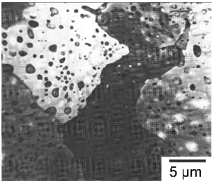
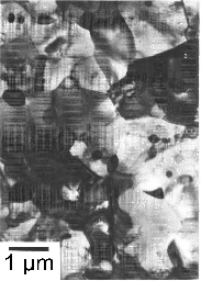
Some surprisingly large values of the fracture toughness, in the range 42–52 \( \text{MPa}\,\text{m}^{1/2} \) have been reported for 52100 type steel in the quenched and tempered martensitic condition, and when isothermally transformed into mixed microstructures of bainite and martensite [176]. The hardness of all the samples tested exceeded 59 HRC. However, the toughness tests were carried out using non-standard procedures, i.e., with the fatigue-induced pre-crack replaced by a spark-machined slit so these are not valid data. It has been argued that three-point chevron-notched specimens can be used to determine the fracture toughness without pre-cracking the samples [504]. Samples with these notches were tested with and without pre-cracking and yielded quite high fracture toughness values from 41–53\( \text{MPa}\,\text{m}^{1/2} \) for samples of 52100 steel heat treated to give hardnesses in the range 60–63 HRC. The significance of these high values of toughness is not clear in terms of comparisons against standard tests.
Dynamic Fracture Toughness
The speed at which a crack propagates is determined by a parameter known as the dynamic stress intensity \(K_{ID} \); it represents the material's resistance to dynamic crack growth and is often referred to as a dynamic fracture toughness, although it is not a single valued material parameter as \(K_{IC} \).
The speed of the crack increases rapidly with the magnitude of the dynamic stress intensity but eventually reaches some terminal velocity beyond which it becomes insensitive to \( K_{ID} \). The value of \( K_{ID} \) at which the crack speed becomes zero (i.e., the crack arrests) is designated \( K_{Im} \) and is usually smaller than \( K_{IC} \) since the stress intensity required to initiate a crack is usually greater than that to propagate it. Fig. 55 illustrates the dynamic stress intensity measured at a crack speed of \( 2 \text{ m s}^{-1} \) for 52100 steel samples taken from tubes, quenched after austenitisation at a variety of temperatures followed by tempering at 160 °C for 1.5 h [505]. It is not clear why the cold-rolled tubes perform better than those which were heat treated from the hot-rolled condition. Blunt-notch impact tests reveal a similar correlation, that cold-working of the steel prior to the heat-treatment needed to produce martensite leads to an improvement in the energy absorbed, although \( K_{IC} \) was not similarly enhanced [60]. The mechanism is unrelated to refinement since other methods of achieving smaller austenite grains did not lead to better toughness. There are data showing that cold deformation leads to an increase in the density of the steel [505] but the mechanism for this is not clear since the original interpretation that the introduction of defects into the microstructure causes densification is incorrect [506, 507].
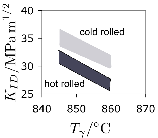
Impact Toughness
The Charpy impact properties of bearings steels are expected to be poor when compared with values typical of the much lower strength structural steels. Undissolved cementite or other coarse carbide particles do not help in this respect. Impact energy measured on un-notched 10 mm diameter cylinders give values in the range 48–71 J, measured at room temperature, have been reported for 52100 type steel [176]. Another study where the sample shape was not specified reports an impact energy range of 43–74 J [508].
Given that the notch toughness of traditional bearing steels in their hardened condition is limited, it is found that the presence of a notch dominates crack initiation during rotating-bending fatigue tests, rather than inclusions. Thus, inclusions are not found on the fracture surfaces of tests on notched samples, whereas the origin of the fatigue crack can be traced to an inclusion when un-notched samples are used [509].
Fatigue
Fatigue is intriguing because in well-designed structures it occurs slowly and leads eventually to failure at stresses much smaller than those associated with the breaking strength of the material. To paraphrase Wöhler [510], rupture may be caused by the repeated application of stresses, none of which equal the carrying strength [511].
Smooth Samples
There are two kinds of fatigue tests where explicit stress concentrations are avoided so that phenomena related to crack initiation can be investigated. In one case, a smooth sample is rotated whilst it is bent so that the surface undergoes cyclic tension and compression with each revolution. The distribution of stress through such a sample is not uniform and there is a neutral axis where the stress is zero. In another test, a sample is loaded axially so that the gauge length is uniformly stressed, with the advantage that a larger volume of material is exposed to the stress, making the detection of inclusion-initiated fatigue more likely. This difference between the bending and axial modes on the exposed volume seems well-established and yet there are still experiments being reported to reach the same conclusion [512]. The results in both cases are expressed as " \(S-N \)" curves, by plotting the alternating stress amplitude \(\sigma_a \) versus the logarithm of the number of cycles \(N \) that cause failure (Fig. 56).
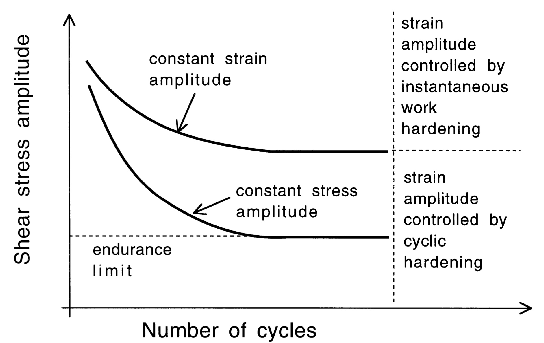
Materials which strain-age exhibit a fatigue limit \((\sigma_a^f) \), which is the value of σa below which failure in principle does not ever occur during cyclic loading. The limit is usually ascribed to dynamic strain-ageing in which the mobile dislocations are pinned by interstitials. Another view is that the limit should be identified with the need for plasticity to spread across grain boundaries for the successful propagation of cracks [514, 515, 513].
For materials which do not exhibit a fatigue limit, it is conventional to define an endurance limit.14 Bearing steels might fall into this category [26] and data from fatigue tests carried out to a billion cycles seem to confirm this [516, 517].
Recent work based on torsion testing has confirmed that there is no observable fatigue limit for the 52100 type steel heat-treated to a hardness range 58–62 HRC [518]. The existence of a true fatigue limit for bearing alloys was in doubt as long ago as 1936 ([519], cited in [518]). Assuming that strain-ageing, in which carbon atoms render dislocations sessile, is responsible for creating a fatigue limit, the absence of the limit could be explained by the existence of mobile dislocations in the martensitic or bainitic steels, or because the microstructure is intrinsically heterogeneous and hence leads to stress concentrations which stimulate dislocation mobility. Indeed, it is possible by inducing strain ageing to increase the endurance limit for 52100 steel in its spheroidised [520] and hardened [521] states. The issue of whether or not a true fatigue limit exists is important in the application of empirical equations of the type used in defining bearing life, as discussed in section 17.2.
The endurance limit \( \sigma_a^{\text{e}} \), which is identified as the stress amplitude corresponding to a fatigue life of say \( N^{\text{e}} = 10^8 \), has to be chosen so as to reflect the life of the component. For example, the endurance limit was historically set at \( N^{\text{e}} = 10^6 \) but many modern bearings are designed to last much longer and hence utilise a larger limit of \( 10^8 \) cycles. The definition of the endurance limit is clear in tests where samples are uniaxially loaded (axial or rotating bending), but it is also used in the context of more complex stress systems associated with rolling contact, to describe the contact pressure which avoids failure for \( N^{\text{e}} = 10^8 \) [118]. In summary [522]:
Practical models for estimating the stress at the endurance limit contain information about the largest defect present in the volume at risk. If the defect is an inclusion then its potency depends on its area \(A_P \( projected on to the plane normal to the applied stress. Thus, the endurance limit when the inclusion size is large ( \(> 1 \( mm) is given by [523]:
Cracks initiate at the free surface of a homogeneous sample either due to the existence of stress concentrations, for example from machining marks, the intersection of grain boundaries with the surface, due to the development of slip steps at the free surface, from surface-breaking inclusions [524] or even unfavourable crystallographic orientations [525]. Fatigue experiments are done under conditions where the maximum stress is less than the macroscopically measured yield strength \(\sigma_y \(. As a result, the mechanisms for the surface initiation of fatigue cracks usually predominate at relatively large applied stresses.
It is intriguing why surface initiation becomes more difficult at low stress amplitudes, so that cracks begin instead from sub-surface non-metallic inclusions [125] or embrittled prior-austenite grain boundaries [527, 526], Fig. 57. This change in the location of fatigue failure is a general observation not restricted to bearing steels [528]. Surfaces of fatigue tensile-test samples are often prepared by gentle grinding or fine machining to ensure a roughness which does not exceed a few micrometers. This process introduces longitudinal stresses up to about -600 MPa, which even after electropolishing to a depth of 20 µm, remain at a level of about -250 MPa [181, 529]. These compressive stresses counteract the applied force in tension so that surface initiation should predominate only at large stresses. Compressive surface stresses introduced by shot-peening lead to a transfer of the fatigue initiation site from the surface to sub-surface even at high cyclic stress [530]. Similarly, the removal of surface stresses by electropolishing transfers the initiation site to the surface even at low stress amplitudes [529]. Specimens which are circumferentially notched, and hence contain stress gradients which focus at the surface, inevitably fail by fatigue crack initiation at the surface [482, 529].
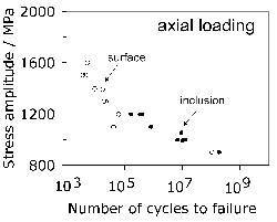
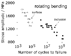
\( S–N \) diagrams for steel SUJ2, \( R = −1 \).
with samples prepared using cylindrical grinding. Open circles represent failure initiated at the free surface; filled circles represent failure originating within the material body. (a) Axial loading, (b) rotating bending tests. Data from [125].Fractographic studies of failed \( S–N \) samples reveal failure modes in three categories. When cracks initiate at the surface, there is a half-penny shaped smooth fatigue-crack (Fig. 58a, [i]) front that propagates into the sample, followed by a rougher region (Fig. 58a, [ii]) where grains have detached at their austenite boundaries, and then rapid fracture. It is suggested [125, 535] that region [i] is generated by the steady advance of a fatigue crack as the stress intensity range exceeds the threshold value \( \Delta K^0_I \). Final failure occurs when the stress intensity at the crack tip reaches the critical value \( K_{IC} \), the fracture toughness of the material. For 52100 type steel, \( \Delta K^0_I \approx 5 \text{ MPa}\,\text{m}^{1/2} \) and \( K_{IC} \approx 20 \text{ MPa}\,\text{m}^{1/2} \). [125].
Fig. 58b shows a classic 'fish-eye' fracture surface due to crack initiation at an inclusion. The features are essentially the same as a surface-initiated crack except that the shape of the fatigue crack is that of a complete penny; fish-eyes can be elliptical in shape when they develop in heterogeneous stress fields. In Fig. 58c the crack has initiated at an inclusion but in the proximity of the surface, giving rise to a so-called 'contact fish-eye'.
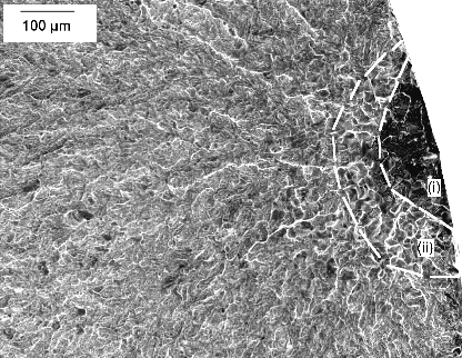
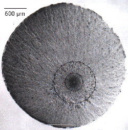
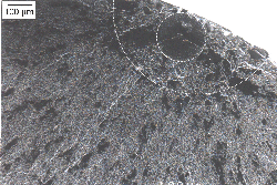
Gigacycle Fatigue Tests
Conventional machines achieve loading frequencies of about 50–1000 Hz. In contrast, piezoelectric devices test smooth samples at 20–100 kHz to rapidly achieve fatigue data up to \( 10^{11} \) cycles [543, 541, 542]. Conventional tests for \( 10^{11} \) cycles would take over a decade, whereas a 100 kHz machine completes the test in less than 300 h.
- Temperature: Sample temperature may increase by some 50 °C due to anelastic dissipations; this is managed by cooling.
- Frequency Response: The material's response at high frequency may differ due to dislocation motion limits.
- Environment: Hydrogen diffusion and corrosive influences are frequency-dependent.
- Defects: Stress intensity factors for artificial defects (e.g., 100 µm holes) don't change significantly between 10 Hz and 20 kHz [553].
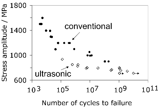
Ultrasonic tests consistently indicate lower fatigue strength than conventional tests for these steels, which is in contrast to aluminium alloys. Furuya [547] noted that fatigue properties deteriorate as the volume of highly-stressed material is increased. Fig. 60 shows a comprehensive comparison, maintaining the observation that high-frequency testing underestimates fatigue strength for SUJ2 and 100Cr6 steels.
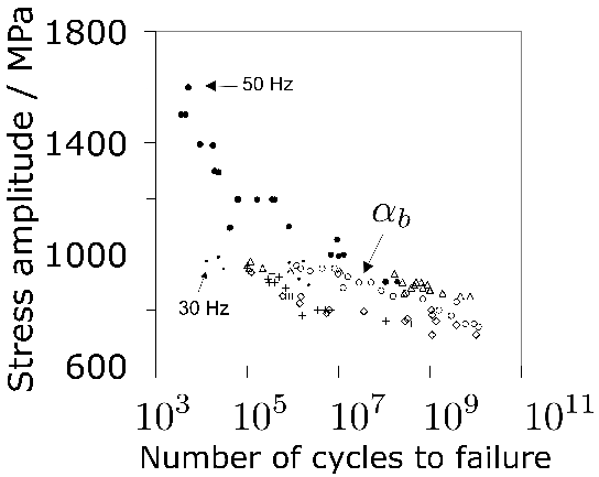
Furuya [547] concludes that large specimens should be used when conducting gigacycle fatigue tests. However, this applies also to conventional low-frequency tests. The important point is to use a sample size consistent with the goal of the experiment, and to use the same risk volume for both conventional and ultrasonic tests if comparisons are to be made.
It may be speculated that the larger strain rates associated with 20 kHz testing makes the steel behave in a more brittle manner — an increase in strain rate is known to raise the shear yield strength in bearing steels [17]. This hypothesis is consistent with data on lower strength steel, illustrated in Fig. 61, where the difference between the ultrasonic and conventional testing is small. The formation of slip bands during testing usually degrades fatigue life because the deformation is heterogeneous and hence intense. It has been demonstrated that in a ductile steel containing only 0.13 wt% carbon, slip bands form during conventional testing but not at ultrasonic loading frequencies, leading to a greater fatigue life [553]. This phenomenon presumably is not relevant in bearing steels which are brittle and hard.
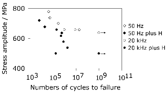
Figure 61: Comparison of S–N diagrams for Fe-0.39C-0.18Si-0.94Mn-0.94Cr-0.2Mo wt%, , generated using conventional push-pull testing at 50 Hz on a servo-hydraulic machine and ultrasonic testing at 20 kHz [556].
Figure 62 illustrates ultrasonic fatigue data from samples which were electropolished in order to reduce the compressive surface residual-stresses that arise when the tensile samples are ground. The results for the steel in the bainitic condition are particularly interesting because there isn't much of a difference between surface and interior initiated failure, emphasising the role of the ratio of residual to applied stress in determining whether damage begins at the free surface or at inclusions within the steel. The figure includes for comparison purposes, data from the alloy in its quenched and tempered condition; these tests were on an hour-glass shaped sample exposed to a relatively smaller risk volume. In spite of this, the bainitic microstructure shows better fatigue resistance presumably because of its greater ductility.
Mayer et al. [557] have conducted variable amplitude fatigue tests; the accumulated damage at any point in the test is approximated by
where \(N_V \) is the number of fatigue cycles implemented at a particular value of the applied stress amplitude. If this rule applies then failure occurs in a variable amplitude test when \(S_d=1 \). It turns out that failure actually occurs at about \(S=0.44 \), i.e. prematurely when compared with expectation from equation 13 [557]. An additive principle of the type embodied in equation 13 may not apply if the mechanism of fatigue damage changes with stress amplitude.
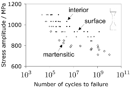
Figure 62: Ultrasonic fatigue tests on 4 mm diameter, 10 mm parallel gauge length samples with \(R=-1 \), 20 kHz. The circular points represent 52100 steel transformed to bainite at 220 °C [181], whereas the triangles represent quenched and tempered martensitic 52100.
Utility of Uniaxial Fatigue Tests
The discussion of push-pull and rotating bending tests highlights the sensitivity of the method to specimen design and risk volume, and of the state of the surface both in terms of roughness and with regard to stresses residing in the specimen surface as vestiges of sample preparation. Tests involving bending expose a smaller volume to damaging stresses when compared with push-pull tests; they therefore are associated with greater fatigue lives, Fig. 63. For the same reason, hour-glass shaped samples will give better performance push-pull tests than those with long, parallel gauge lengths. And larger diameter samples should fail after fewer cycles because the probability of finding large inclusions increases with the exposed volume.
The data from these experiments cannot be used to assess the performance of the material in rolling contact fatigue. Neither the stresses, the shape of the imposed stress cycle, nor the failure mechanisms are identical for uniaxial and rolling contact tests. The question then arises as to why this method remains popular as a method of studying the fatigue properties of bearing steels:
- The method is cheap and in the context of bearings, can be used for the qualitative comparison of different steels, in particular the susceptibility to inclusions as initiating sites for fatigue. For assessing inclusions it is important for the samples to be designed with a significant parallel gauge length in order to expose a greater volume of material to the maximum stress. The technique has been used to show that at the same hardness in 51100 steel, the coarser cementite present in tempered martensite when compared with lower bainite, leads to a reduced endurance limit in the former microstructure [39].
- The test has frequently been used to demonstrate qualitatively the role of hydrogen in accelerating failure.
- The test is suited well to determine the role of surface treatments on fatigue performance. At the same time, most of the experimental data published do not reveal the stress state of the surface and it is well-established that shallow residual stresses introduced during sample preparation determine the location of fracture [533].
- It is easier in tests on smooth specimens to observe the initiation site, and hence to characterise the inclusions that are responsible for damage [386]. Titanium carbides and carbonitrides can be more damaging in axially loaded samples than in rolling contact fatigue [125, 127].
However, it remains the case that none of the data can be used in design as far as rolling contact loading of bearings is concerned. Such tests are useful in assessing 'structural fatigue' of relatively smooth components, i.e. to cyclic loads which are not related to rolling contact, in which case the R ratio must be chosen to suit purpose.
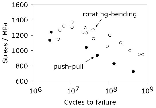
Figure 63: Comparison of push-pull (\(R=-1\)) and rotating-bending tests on SUJ2. All of the failures initiated from within the steel. Data from [175].
It is not entirely clear why uniaxial fatigue tests on bearing are conducted using an R ratio of \(-1\). This does not approximate what happens in rolling contact fatigue where mode II sliding shear is relevant, and is better represented as a combination of torsion and compression. It is known that tests conducted using \(R=0.05\) given better fatigue lives than \(R=-1\) [175].
Fatigue Crack Growth Rate
There are circumstances in which the life of a component is limited by the rate at which cracks grow rather than by the crack initiation event. The fracture mechanics approach addresses the advance of sharp cracks per cycle of fatigue loading (\(da/dN\)) as a function of the stress intensity range \(\Delta K\). Figure 64 illustrates the general trend with perceptible growth beginning at a threshold value \(\Delta K^0\), followed by a Paris law regime in which
and then rapid propagation as the maximum stress intensity approaches the fracture toughness \(K_C\) of the material. \(m\) is known as the Paris constant and is of the order of 3 for bearing steels [558].
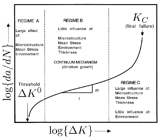
Figure 64: Variation in fatigue crack growth rate as a function of the stress intensity range (adapted from [559]).
Typical values of the crack advance per cycle for 52100 steel are illustrated in Fig. 65, where it is seen that an increase in the austenitisation temperature leads to more rapid crack growth whereas higher tempering temperatures are associated with lower crack rates [60]. The threshold \(\Delta K^0_I\) in mode I loading is in the range 3.3–8.3 \(\text{MPa m}^{1/2}\) [60].
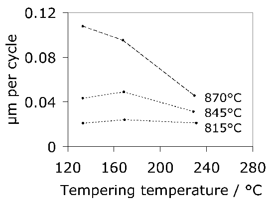
Figure 65: Crack advance per cycle at \(\Delta K=10 \text{ MPa m}^{1/2}\) for 52100 steel austenitised at various temperatures [60].
As might be expected, fatigue crack growth rates decrease when the crack front encounters a compressive stress in case-hardened steels, and if the carburising results in a tensile residual stress field, then the crack accelerates [562, 343, 561]. The influence of residual stress can be approximated by an effective stress intensity given by \(\sigma_i d_i^{1/2}\).
Fig. 66 compares the crack growth rates observed in 52100 steel and M50 steels. The M50 steel exhibits a significantly slower growth rate, presumably because of the vacuum arc remelting procedures and the absence of cementite particles.
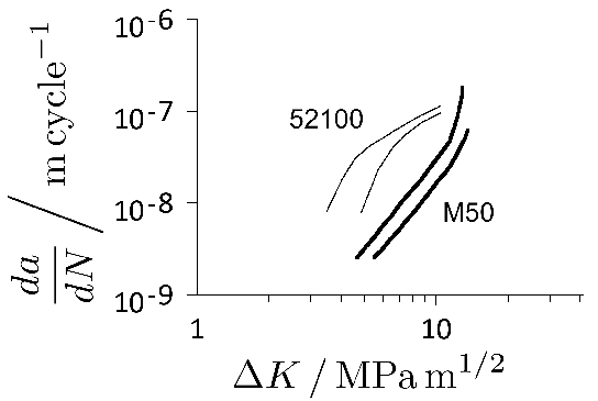
Figure 66: Fatigue crack growth rates for 52100 steel (61.5–62.5 HRC) and M50 (62 HRC), both tested at \(R=0.1 \(.
Rolling Contact Fatigue
The fatigue life of bearings is determined primarily by three factors [563]: the detachment of material (spalling) following the initiation of cracks below the contact surface, spalling due to surface irregularities and due to distress caused by surface roughness or inadequate lubrication. Modern bearing steels are clean but inclusions persist.
Hertzian Contact
The analysis presented here is for an idealised situation involving only elastic deformation. This formalism is useful in illustrating the consequences of rolling contact. For detailed quantitative work, a full three-dimensional elastic-plastic model which includes work-hardening must be used [565].
The stress field created when two frictionless bodies are pressed together into elliptical contact was first studied by Hertz [567, 566]. If the curvatures are \(R_1 \) and \(R_2 \), then \(R = (R_1^{-1} + R_2^{-1})^{-1} \) is the relative curvature. Assuming a circular contact area of radius \(r_0 \), the variation of contact pressure \(p \) as a function of distance \(r \) from the centre is given by:
where \(w \) is the applied load and \(E \) is the Young's modulus. The contact pressure \(p \) in the surface at \(z=0 \) is illustrated in Fig. 67b.
The corresponding radial stress \(\sigma_r \) and tangential stress \(\sigma_\theta \( within the contact circle are:
Outside the contact circle,
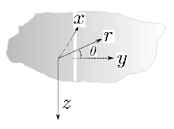
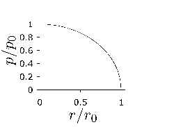
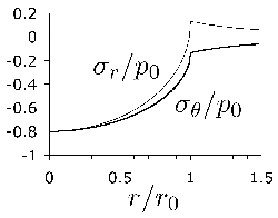
Figure 67: Hertzian contact stresses. (a) Coordinates definition. (b) Variation of normalised pressure at \(z/r_0=0 \). (c) Corresponding variation of \(\sigma_\theta \) and \(\sigma_r \).
The stresses along the \(z \)-axis at \(r=0 \) are given by:
where \(\tau_{\text{max}} \) is the maximum shear stress acting on planes at 45 ° to the \(z \) and \(y \) axes. The orthogonal shear stress \(\tau_O=0.25p_0 \) acts on planes parallel or normal to the bearing raceway, reaching a maximum value at a depth \(z=0.25r_0 \) [568]. The range of the orthogonal shear stress is \(2\tau_O \) since it reverses as the rolling contact traverses a point.
The equivalent stress, often known as the von Mises stress, is given by
assuming a distortion energy criterion. Here \(\tau_e \( is the equivalent shear stress. Other expressions can be found in [569].
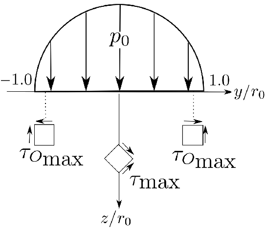
Many studies have been conducted to determine which shear stress— \(\tau_{\text{max}} \), \(2\tau_O \), or the von Mises shear stress—is most damaging in the context of fatigue [302, 314]. Their roles can, in principle, be determined by comparing the respective stress distributions against the location of maximum damage in experiments; thus, cracks have been observed to initiate at inclusions located at the shallower depth corresponding to the orthogonal shears [147]. However, whichever shear stress is considered, the maximum occurs below the contact surface, and as will be seen later, this has significant consequences for the development of damage. Notice that the shear stress is proportional to the contact pressure \(p_0 \), but the proportionality constant will depend on the ellipticity of the contact. The ellipticity, defined as the ratio of the minimum to maximum diameters, is typically **0.80** for the inner race of a bearing [570].
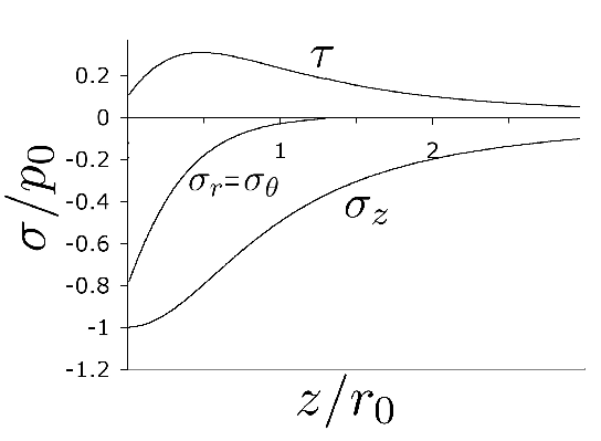
If plastic yielding is avoided, then the contact will not leave any residual stresses or damage after the loading cycle is completed. If the yield criterion is exceeded, however, then there are three phenomena which occur during cyclic contact [571]15:
- Residual Stress:
- The induced residual stresses combine with the applied stress to produce a state of stress which lies within the yield envelope.
- Work Hardening:
- The work hardening resulting from microplasticity increases the yield strength.
- Contact Geometry:
- The plasticity may result in a larger area of contact and hence a reduction in the contact pressure.
These phenomena are associated with plastic deformation but eventually lead to deformation which continues in an elastic manner; the process leading to the latter state is called shakedown. More generally, elastic shakedown is said to occur if all the components of the plastic deformation tensor become constant [573]. The shakedown limit for a given loading history is the largest stress that can be applied to a component without inducing ongoing plastic deformation. Micro-plastic deformation, which depends for example on localised stress concentrators, cannot be ruled out even when applied stresses lie within the yield envelope [574]. Some typical values of the shakedown limits are given in Table 16.
| Contact Type | Steel 52100 (MPa) | Steel 1070 (MPa) | Operating Pressure (MPa) |
|---|---|---|---|
| Line contact ( ) | 2040 | 2560 | 1400–1800 |
| Point contact ( ) | 2400 | 3010 | 2000–2800 |
The shakedown limit will be different in a material which, in its initial unloaded state, contains residual stresses. Furthermore, a steel containing retained austenite will have a longer shakedown period than one which does not, due to the progressive transformation of the austenite into martensite under the influence of stress [565]. On the other hand, the work-hardening resulting from the formation of fresh martensite leads to a smaller plastic strain prior to achieving the shakedown condition; this is reflected in the development of a smaller groove depth during rolling contact [565]. According to Voskamp [575], the first stage of bearing operation leads to the transformation of austenite and cyclic hardening, while prolonged rolling contact causes microstructural changes associated with cyclic softening so that the shakedown limit is exceeded and damage accumulation accelerates, leading finally to failure. The details of these microstructural changes are discussed in section 21.
The shakedown process can be visualised more simply in terms of a constant applied-stress fatigue test. The alternating stress amplitude is fixed, but the plastic strain per cycle decreases as the material cyclically hardens, until eventually the strain ceases to increase on a macroscopic scale [100, 576], Fig. 70a. The progressive reduction in plastic strain during cyclic loading is illustrated in Fig. 70b for 52100 steel in its martensitic and bainitic conditions. In the former case, the decomposition of retained austenite during the early stages contributes to the plastic strain recorded, whereas the absence of retained austenite in the bainitic condition means that the total plastic strain is rather small at all stages of deformation.
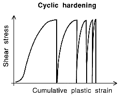
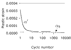
While the discussion here has focused on deformations occurring as a consequence of contact, the implementation of the bearing into service can introduce additional stresses which have a dramatic influence on fatigue behaviour. Bearings are sometimes press-fitted onto shafts, introducing hoop stresses, and the speed of rotation can give rise to significant centrifugal forces, which are greatest on the inner ring. It has been estimated that the combination of these two stresses with Hertzian loading can reduce fatigue life by **90%** in aeroengine bearings [577]. Any tangential tensile stress is detrimental to bearing performance [578]. Aircraft engine bearings are particularly susceptible because they involve heavy interference fits and high rotation speeds. The centrifugal forces associated with these speeds can generate large contact stresses ( \(\approx 2 \( GPa) between the rolling elements and rings, making the bearing sensitive to catastrophic failure following damage such as spall formation [324, 303]. This is why, for example, M50NiL is used for the bearing rings rather than M50; in its case-hardened condition, the former possesses a higher core toughness.
Model for Rolling Contact Fatigue
The calculations of contact stresses could in principle form the basis of methods for predicting failure. Rolling contact fatigue life might be estimated from some combination of models of the nucleation and growth of cracks in fatigue loading. An example [558] of such an approach is presented here with the aim of illustrating the framework; it is appreciated that there are additional complexities which must be accounted for when dealing with real scenarios, but such an approach can nevertheless be stimulating. Actual models used in declaring bearing life are described in section 17.
Uniaxial fatigue tests of smooth samples test initiation and could form the basis for assessing nucleation. The slope of the \(\log\{S\} \) versus \(\log\{N\} \) curve (Fig. 56) when testing smooth specimens for fatigue crack initiation, between the limits \(\sigma_u \) (ultimate tensile strength) and \(\sigma_a \) tends to be a straight line, described as the Basquin law [579]:
where \(N_i \) is a crack initiation life in cycles, assumed to correspond to a point where the crack reaches a specified detectable size \(a_d \). \(\sigma_{a_i} \) is the tensile stress amplitude calculated from the maximum shear stress at the nucleation site. An equation of this form can in principle be derived using dislocation theory involving the accumulation of dislocation dipoles at the obstacle interface, until the strain energy of the accumulated dipoles reaches a critical value [580]; in practice, however, the stress exponents obtained from theory differ significantly from those observed in crack initiation from inclusions in bearing steels [147].
The location of crack initiation is assumed to correspond to the point where the ratio of the maximum shear stress to microhardness is at a maximum, although this cannot be generally true since it is inclusions which initiate cracking in practice. The location of the maximum shear stress and inclusion need not coincide, and a lower stress region containing a weak inclusion may initiate failure.
Having defined the nucleation stage, crack propagation is represented by the Paris law so that a combination of the nucleation and growth models give an equation of the form:
where \(a_5 \), \(a_6 \) and \(a_7 \) are empirical constants [558]. In the context of rolling contact fatigue, Choi argues [558] that the model should underestimate the actual life since it does not include a spall propagation component (section 15.10).
This discussion above does not consider the micromechanisms of crack evolution, nor of the crack morphologies. It has been shown in a rather elegant study [581] that the initiation of cracks is governed by the superposition of the local stress field in the vicinity of an inclusion, with the applied contact pressure. It follows that the starting orientation of the crack, assuming that this is determined by the stress field alone as opposed to fracture along features such as prior austenite grain boundaries, will be different from the path taken by the fracture front when it is beyond the influence of the inclusion. The initiation life is defined in this context by the change in the propagation orientation of the crack, and this turns out to be about a tenth of the total rolling contact fatigue life (including some sliding) tests done at realistic Hertzian pressures. The crack orientation at the start tends to be variable since it is the local structure of the inclusion and matrix which dominates the process. The subsequent change in orientation is governed more by the continuum components of the applied stress field and this is more predictable, at some 15° to the raceway surface. However, this angle can be dramatically modified when the crack encounters residual stress fields in the proximity of the raceway surface. If the circumferential residual stress is sufficiently large and compressive then the subsurface crack may propagate parallel to the raceway without breaking the surface.
Failure
The life of a component is determined by its ability to perform its intended role; when it is no longer able to do this, it is considered to have failed. In the case of ball-bearings such as the one shown in Fig. 71, a failure is considered to occur when the bearing is no longer able to perform rotations or when rotations take place with excessive vibrations and noise. Failure may also occur in a more dramatic manner by fracture through the entire section of a bearing component. Complete failures happen in very few cases because the bearings are stopped when vibrations and noise are detected beyond predetermined thresholds; continued use leads to seizure. Vibration and noise normally arise due to the formation of spalls and pits at the contact surface between the raceway and the balls [582].
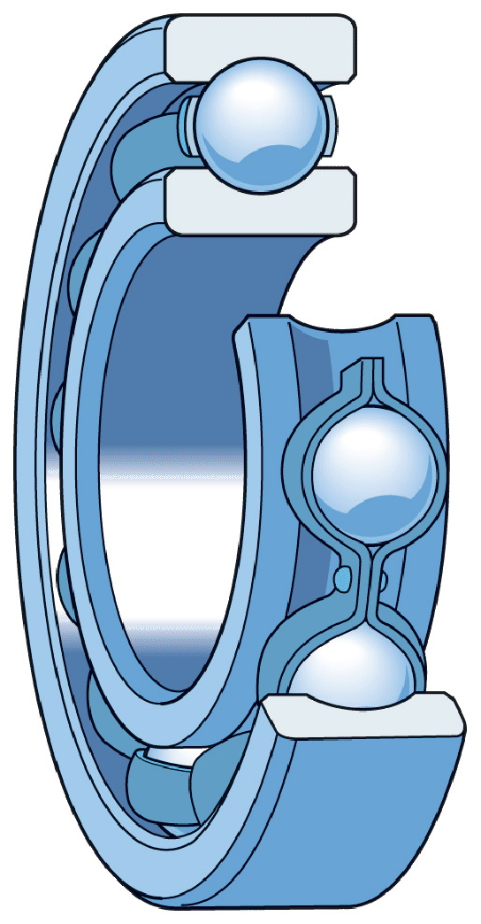
There are many causes why a component subjected to contact fatigue can fail. The component will be subjected to wear if the lubrication is not appropriate. Indents eventually appear on the contact surfaces if the lubrication contains dust or is not filtered [583]. If the load is too high, seizure will occur, but if all of these are avoided then the only alternative and viable cause of failure is due to the continuous accumulation of damage which can be accelerated by plastic deformation and strain or stress-induced structural changes due to service load, leading eventually to spalling [586]. The useful life is dependent on the stressed volume, alternating shear stress, number of stress repetitions, depth of alternating shear stress and the state of residual stress [587].
Bearings are generally regarded as components which have high surface-integrity and hence the fatigue problems that occur usually are attributed to damage within the steel itself. In 52100 steel quenched and tempered to a hardness of 753 HV, the endurance limit on smooth-specimen tests has been determined to be \(\tau_a = 600 \) MPa for \(10^7 \) cycles [18]. When crack-like features were introduced at the otherwise smooth surface, the crack propagation rates were found to be extremely slow at less than \(10^{-11} \) m cycle-1.
Rolling contact fatigue is a common type of failure encountered in bearings which are well-lubricated so that other mechanisms of damage originating at the contact surface do not determine life. It is influenced by parameters such as contact pressure, material properties, lubricant properties, surface roughness, amount of relative sliding or slip in the contact, microstructure (including retained austenite content), residual stresses and inclusion size and nature [589, 185]. It differs from structural fatigue (bending or torsion) in that the cyclic stress originates in Hertzian contact, when a curved surface rolls over another curved or flat surface under normal load. The mechanism for failure under these circumstances was first proposed by Suh [590]; near-surface plastic deformation leads to the heterogeneous nucleation of voids or microcracks which then grow or connect by a fatigue mechanism [227].
In tests designed to monitor fatigue crack growth, sliding shear at the crack faces is described as mode II loading which is fully reversed ( \(R = -1 \)) in order to replicate what happens during rolling contact. Stresses applied normal to the crack faces fall into the category of mode I, which is experimentally easier to apply, but is not representative of rolling contact. In fact the mode II shear is superimposed on a compressive stress during rolling contact; tests can be conducted to simulate these conditions by applying both torsion and compression simultaneously to cylindrical samples. However, there is some evidence of a qualitative correlation between fatigue crack growth rates monitored in mode I loading, and rolling contact fatigue results [592].
Threshold stress intensities \(\Delta K^0_{II} \) and \(\Delta K^0_{III} \) for the shear modes II and III respectively, have been determined by observing non-propagating cracks in cyclic torsion tests ( \(R = -1 \)) and have been found to be in the range 6-20 MPa m0.5 (Fig. 72), with not much of a difference between the values for modes II and III [595, 18].
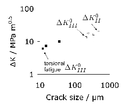
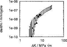
Failure is usually defined by spalling, which begins with microcracks initiating below the bearing surface, followed by coalescence of multiple microcracks which then reach the surface. The detailed topology of the internally cracked surface depends on factors such as the rolling contact stress, the temperature and any crystallographic texture that develops under the bearing surface during prolonged fatigue [598]. It is found that relative to the rolling direction, the leading edge of the spall is sharper than that which trails, and there may be further fine-scale damage on the trailing edge through debris created by spalling [599].
Aeroengine Bearing Failures
Bamberger [283] has reviewed the understanding of aeroengine bearing materials. He concludes that although sub-surface nucleated fatigue-spalls are the most understood of phenomena, well-designed and processed bearings made using high-quality steels rarely fail from this mechanism. Fatigue failures in these circumstances usually occur only when the bearing is overloaded. In practice, experience suggests that only some 10% of highly-loaded bearings fail due to sub-surface initiated fatigue. The vast majority ( \(\approx \)70%) of operational failures are attributed to surface distress where damage occurs due to pitting, surface fatigue, scoring, debris damage, contamination, plasticity, smearing etc. [283]. Corrosion is a contributing factor to another 10% of failures.
Role of Retained Austenite
The mechanically-induced transformation of austenite during rolling contact fatigue can be beneficial in hardening regions where the stresses or strains are localised. Such transformation may also give rise to beneficial residual stresses. Many of the experiments probing these phenomena are done at unrealistically large stresses; for example, for contact pressures in excess of 5 GPa, it is reported that a greater retained austenite content is beneficial to the life of 52100 steel [185]. The \(L_{50} \) life doubled with a doubling in the \(\gamma_r \) content. Any such benefit would naturally have to be weighed against other consequences such as a reduced elastic limit or dimensional stability.
Surface Initiated Cracks
Crack nucleation at the surface is not common in rolling contact because of the compressive stress that exists just below the contact regions [610]. It is, however, possible for fatigue cracks to originate from the contact surface in the presence of appropriate stress concentrations or thermal damage. Surface-initiated spalls due to features such as machining marks are easily identified using fractography because the marks influence the shape of the spall [612].
A complication from surface initiated cracks is that lubricant or corrosive media can penetrate the open crack [614], and transmit the Hertzian contact pressure at the mouth of the crack to underlying crack faces. The penetration of the lubricant is most effective when there is a combination of sliding and rolling contact which helps to open up the crack mouth [591]. When penetration does occur, the resultant periodic and large pressure pulses at the crack face play an essential role in the propagation of fracture [615].
Accelerated Testing
Bearing life is usually declared by conducting rolling contact fatigue tests on full-scale bearings. However, accelerated tests are useful in the assessment of new materials or technologies. Such tests may involve much larger contact stresses than would be experienced in service and hence cannot be used as an indicator of bearing life. Empirical correlations exist; for example in the case of M50 bearings, the spalling-limited life in rolling contact at two different Hertzian pressures are related by:
 (24)
(24)
where \(A_1 \) and \(A_2 \) represent the product of the width and length of the respective wear tracks. Element testing methods suffer from the fact that small volumes are exposed to the maximum stresses, and that the contact stresses may be so large (5 GPa) as to be above the shake-down limit of the alloy.
It is also possible that at the very high loads associated with accelerated testing, the material fails by mechanisms not related to those that arise during service [623], rendering the results useless in assessing bearing life under realistic conditions. The smearing of cracks by plastic deformation is a case which occurs only at abnormal rolling contact stresses.
Fretting Wear and Rolling Contact Fatigue
Bearing quality is often associated with acoustic and vibrational performance because the resulting small oscillatory motions cause wear and material transfer between the abutting surfaces. Fretting occurs when two bodies in contact rub against each other, with the rubbing action described in terms of a contact stress, and the amplitude and frequency of the slip oscillation. When the amplitude is a few micrometers, the oscillations lead to the initiation and propagation of fatigue cracks. Larger amplitudes lead to fretting wear and damage, and the creation of debris that enhances the abrasion. It is this loose and voluminous debris which is the characteristic feature of fretting wear [626]. The problem can be made worse when debris is retained in the affected zone because the fretting surface is much larger than the oscillation amplitude [627]. The parameters that influence fretting include relative humidity, temperature, frequency, the roughness of the surfaces in contact, normal force, displacement amplitude and the number of cycles [628]. The length of the fatigue crack initiated in fretting is thought to be proportional to the width of the contact patch and this is important in determining whether the crack propagates [629]. Some data are illustrated in Fig. 75, showing how weight loss due to fretting corrosion varies with the oscillation frequency and material hardness.
Surface damage due to fretting influences rolling contact fatigue by acting as stress concentrators which in turn cause premature spalling. Experiments on M50 steel reveal that fretting wear created using a slip amplitude of 21 µm and 10 Hz with a Hertzian contact pressure of 1.1 GPa can lead to significant reductions in the rolling contact fatigue life measured with a contact pressure of 3.4 GPa, as illustrated in Fig. 76 [631].
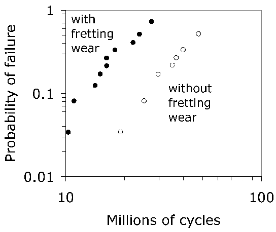
Fatigue and Hydrogen
A body of evidence has established that the presence of hydrogen in bearing steels leads to a deterioration in mechanical properties, including the resistance to fatigue [634, 633, 635], irrespective of the mode of loading.
Phenomena associated with damage, such as White matter, also become more prominent when cyclic stress is applied in the presence of hydrogen. This is why traces of the decomposition products of lubricant [636], water in the lubricant used in bearings [637]17, water created through chemical reactions [135], or exposure to hydrogen sources through other corrosion reactions, can lead to a reduction in bearing life. It has long been known that operating bearings in a hydrogen atmosphere leads to hydrogen embrittlement and extensive surface pitting and flaking [639]. Recent work has shown that if hydrogen is present in the atmosphere around a ball bearing, it can be mechanically squeezed into the steel [640]. Hydrogen sulphide (H2S) has a similar effect to hydrogen because it inhibits the recombination of hydrogen atoms at the metal surface [635].
Hydrogen has an undesirable influence on both the 52100 type and stainless steels such as 440C [641]. For reasons which remain a mystery, its penetration into 440C during hydrogen charging is relatively reduced so that the deterioration in fatigue properties is proportionately smaller (Fig. 77a) [635]. One possibility is that the high chromium concentration in 440C retards the diffusion of hydrogen, as seen in the comparison of diffusion coefficients in Fig. 77b [642].
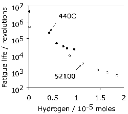
(a)
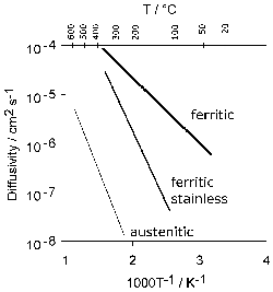
(b)
It is astonishing that the concentration of hydrogen that leads to perceptible degradation can be as small as 1 part per million (ppmw), and even this value may represent different forms of hydrogen within the steel. Diffusible hydrogen is that which is in solid solution or is weakly trapped within the steel; it can migrate through the steel and escape into the atmosphere. In order to study the effect of such hydrogen on fatigue within a time scale which avoids significant loss by diffusion, it is necessary to use high frequency (20 kHz) ultrasonic loading. Such tests have been shown to approximate conventional low-frequency push-pull fatigue experiments in samples not charged with hydrogen [27], with the results being largely independent of frequency [542].
On the other hand, tests which monitor fatigue crack growth rates show a strong dependence on frequency, with crack advance occurring some 30 times faster in hydrogen charged samples relative to uncharged specimens when tested at 0.2–20 Hz; the difference vanishes when the frequency is increased to 20 kHz [644, 645]. It is postulated that this is because hydrogen has time to accumulate at crack tips at low loading frequencies, thus giving rise to slip localisation and a decrease in the plastic zone size at the crack tip [645]. This is confirmed by observations on austenitic stainless steels, where hydrogen diffusivity is about three or four orders of magnitude slower than in ferrite (Table 17).
| Steel | Diffusivity / m2 s−1 |
|---|---|
| 304 (γ) | 1.1 × 10⁻¹⁵ |
| 316 (γ) | 2.0 × 10⁻¹⁵ |
| 316L (γ) | 2.4 × 10⁻¹⁶ |
| 405 (α) | 2.8 × 10⁻¹² |
Fig. 78 illustrates tests on 52100 steel in which specimens were charged with hydrogen and immediately tested using ultrasonic loading [27]. There is a marked deterioration in the fatigue strength in the presence of hydrogen. The fatigue properties recover when the hydrogen is permitted to escape from the steel prior to testing, as illustrated by the single black point in Fig. 78. This confirms that it is the diffusible hydrogen that does the damage [647], rather than any that is trapped at interfaces.
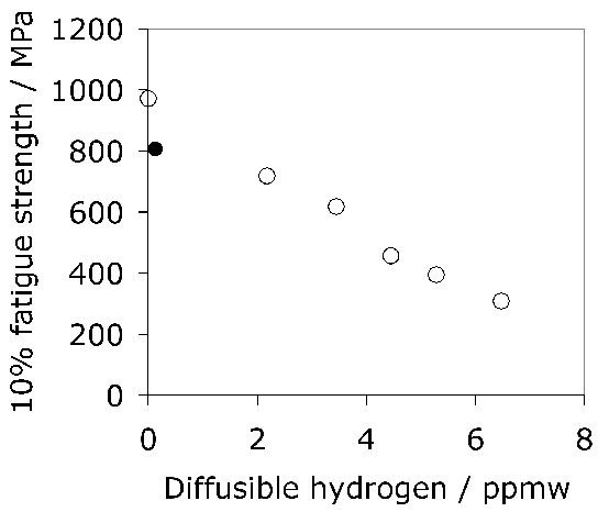
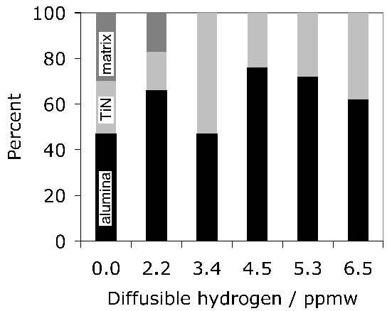
Neglecting the few surface initiated failures, fish-eye cracks initiated in the hydrogen-free sample at alumina or TiN inclusions, or from an unspecified source within the matrix (this could, for example, have originated at the prior austenite grain boundaries given the high phosphorus concentration of the steel used, **0.016 wt%**). The effect of hydrogen was to eliminate the matrix failures and increase the proportion of failures at TiN particles. **Figure 79** summarises the sources of crack initiation as a function of the diffusible hydrogen concentration. Alumina is responsible for the majority of failures, especially in hydrogen-charged specimens; Matsubara and Hamada [27] attribute this to the development of tensile stresses around the alumina, arising during heat treatment due to differential thermal contraction [648], and the migration of hydrogen to those locations. Notice that the presence of hydrogen in the vicinity of the alumina particles seems to degrade fatigue properties, whereas that trapped in the coherency fields of vanadium and molybdenum carbides leads to an improvement in the resistance to hydrogen-induced static failure [649].
A popular mechanism used to explain the interaction between fatigue and hydrogen is that the latter enhances dislocation plasticity [652, 651] by reducing the barriers to dislocation motion. This in turn is supposed to lead to localised deformation in the vicinity of the fracture surface, giving the appearance of brittle fracture. Although this interpretation is based on localised enhancement, macroscopic observations are used to back the argument. For example, **Figure 80** shows a tensile test conducted in which pure iron was subjected to hydrogen charging, illustrating the large reductions in flow stress that occur when the charging current is switched on. This softening is assumed to promote localised plasticity which in turn stimulates the development of White matter.

The mechanism by which hydrogen is supposed to reduce the barriers to dislocation motion is based on the decoration of the dislocations by hydrogen atoms. For this mechanism to be effective the dislocations must move sufficiently slowly for the hydrogen to continuously remain bound to the dislocations [656]. It is questionable whether the softening phenomenon applies during the process of rolling contact fatigue with high-frequency cyclic stresses.
The softening of pure iron due to hydrogen is in stark contrast to its well-known effect in embrittling ferrite by raising the ductile-brittle transition temperature, thus promoting cleavage fracture [647]. Hydrogen embrittlement leads to a dramatic reduction in ductility and toughness, particularly of strong steels [657]. **Figure 81a** illustrates a typical result where a Fe-0.22C-1.05Mn-0.26Si wt% steel is tested with and without hydrogen charging. There is evidence that cracking precedes the formation of white-etching matter during rolling contact fatigue in hydrogen-charged 52100 type steel, suggesting microscopic fracture is responsible for accelerated damage rather than increased plasticity [658].
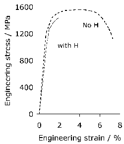
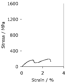
To summarise, the mechanism of hydrogen-enhanced local plasticity should not be considered established in bearing steels, as deterioration could follow Directly from classical embrittlement theory, whereby cleavage fracture is promoted at the expense of macroscopic ductility.
Hydrogen Trapping
The total concentration of hydrogen in a steel ( \(c^H_T \)) is the sum of that which is in solid solution ( \(c^H_S \)) and a residue which is trapped at a variety of sites [669]:
where \(j \) represents the type of trapping site, \(n^H \) is the fraction of filled trapping sites, \(N^H \) is the total number of sites, and \(k^H \) is a constant. For dislocations, \(N^H_{\text{dislocations}} \approx \pi b^{-1}\rho \) where \(b \) is the Burgers vector and \(\rho \) the dislocation density. The binding enthalpy ( \(H_B \)) estimates the fraction of occupied traps:
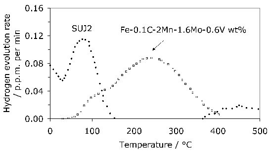
Spall Propagation
The formation of an isolated spall represents the beginning of the end of useful life. The indent left is repeatedly impacted by rollers, leading to material removal at the leading edge. **Figure 83** shows the development of severe damage growing along the rolling direction.
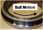
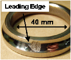
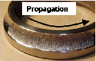
Analysis shows that residual stresses along the surface following repeated impacts become tensile, exceeding **2 GPa**. Cracks form and segments break away, allowing the spall to propagate. Pitting can also be initiated by local thermal treatments that change the microstructure [677].
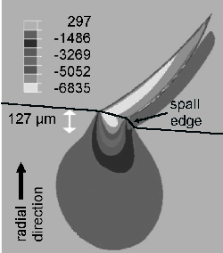
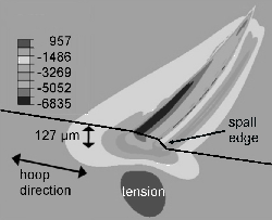
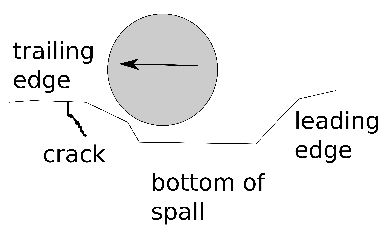
Toughness and Rolling Contact Fatigue
Steel toughness influences rolling-contact fatigue life, especially in environmental conditions such as water in the lubricant [20]. In **1C-1.5Cr** steel, a lower bainitic microstructure can be produced with comparable hardness to tempered martensite. It is argued that the greater toughness of lower bainite leads to better fatigue performance, failing by slow wear rather than dramatic fracture [679].
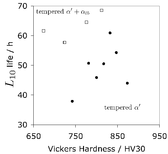
Modifying **52100** steel with molybdenum also improves both toughness and rolling contact fatigue performance by mitigating phosphorus effects [28].
There is some interesting work in the context of the rolling-contact fatigue of back-up rolls used in steel mills [617]. The rolling-contact life of surface-initiated cracks scales with the microstructural parameter \(\sigma_y \sqrt{d_s} \), where \(\sigma_y \) is the yield strength and \(d_s \) is the width of the bainite sheaves. The latter controls the effective grain size and hence determines the deflection of cracks across large misorientation boundaries, whereas the former is related to the ease of plasticity.
Surface Distress
Failures of high-speed bearings sometimes occur through a phenomenon known as surface distress. There are many mechanisms which result in this kind of damage. Particle-contaminated lubricants can cause raceway indentations (Fig. 86) [680]. The partial breakdown of lubricant films and the resulting contact at asperities leads to the formation of small cracks which develop into shallow craters. The damage due to such contact can be reduced if a minimal thickness of lubricant film is maintained to prevent local welding between asperities [681]. There is a distinction made, therefore, between elastohydrodynamic lubrication, in which the film is sufficiently thick to prevent interference between asperities, and the microscopic version of this which prevents the welding of rough surfaces.
The development of surface damage is therefore not simply a material (steel) issue, but involves the complete system including surface engineering. For example, the pressure dependence of the shear strength of the lubricant can influence the nature of the pits that eventually develop on the bearing surfaces [682]. The pits are caused by the large pressure gradients that develop close to the bearing surface, and corresponding large shear stress gradients.
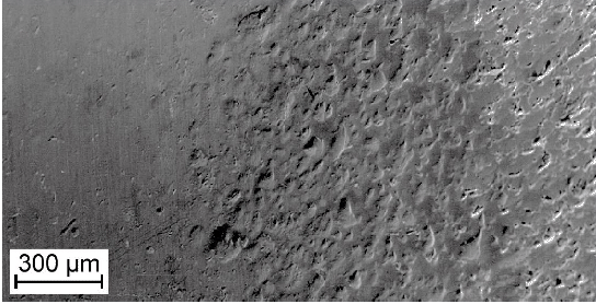
Bearing Life
It is useful to emphasise at the outset that full-scale experiments which assess the life of a manufactured bearing are not precisely reproducible. Scatter is said to occur when the outcome is different even though an experiment is repeated without changing the control parameters [683]. Repeated rolling contact fatigue tests on bearings exhibit scatter because there are parameters which cannot in practice be reproduced—for example, the probability of finding inclusions in the volume of the test sample at greatest risk. Real materials are heterogeneous, and bearing steels are no exception. The heterogeneities are usually regarded as randomly distributed, forming the basis of models which account for scatter [684].
The Weibull Distribution
A Weibull probability density function has the form:
where and are positive constants. The cumulative probability distribution for this two-parameter Weibull model is obtained by integration:
Associated with each such distribution is a ‘failure rate function’ :
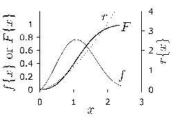
(a)
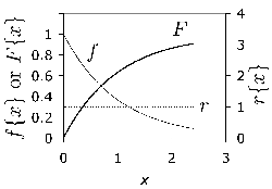
(b)
Practical Methods for Life Assessment
The common method for estimating the life of bearings was proposed by Lundberg and Palmgren [689]. For a specific probability \(S_0 \(:
On this basis, the life \(L_{10} \) was related to bearing loading by:
where \(D \) is the dynamic load capacity, \(P \) is the equivalent applied load, and \(p \) is an exponent (3 for ball bearings, 10/3 for roller bearings) [302].
Residual Stress
Residual stress remains in a body after processing or use. In rolling bearings, compressive stresses are beneficial if localised at the surface. The effect on life is expressed empirically as:
Causes of Residual Stress
Grinding induces tension into the surface when heat tempers the structure, causing shrinkage (Fig. 88). Conversely, if the surface temperature causes austenitisation, subsequent martensitic transformation leaves the surface in compression.
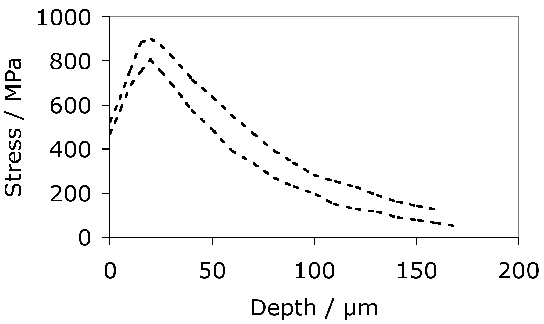
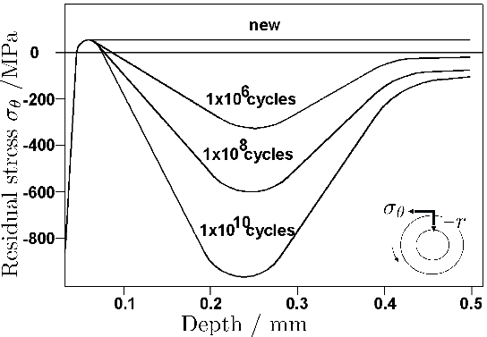
Retained Austenite
To summarise, retained austenite is an important phase in common bearing steels based on a predominantly martensitic microstructure. While its decomposition affects dimensional stability, its role in fatigue remains subject to contradictory studies.
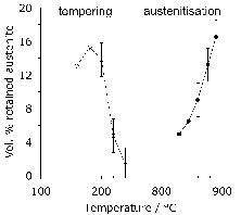
(a)
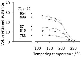
(b)
Quantitative Estimation
The fraction of austenite ( \(V_\gamma \() can be calculated using the Koistinen and Marburger equation [712]:
where \(T_Q \) is the temperature to which the steel is cooled and MS is the martensite-start temperature.
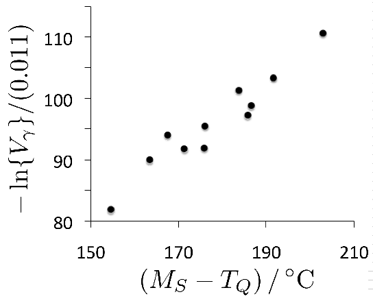
There are nevertheless difficulties in applying this method to bearing steels for two reasons. First, it is the carbon concentration in solid solution that determines the martensite-start temperature, whereas most bearing alloys are austenitised at a temperature which leaves some cementite particles undissolved. It cannot be assumed that the time at the austenitisation temperature is sufficient for the fraction of cementite to correspond to equilibrium [106]. The role of the microstructure prior to austenitisation is clear from the work of Stickels [182]; Table 20 shows how the retained austenite content is sensitive to both the austenitisation conditions and the initial microstructure.
| Initial microstructure | Austenitisation treatment | % \(\gamma_r \) |
|---|---|---|
| Spheroidised carbides in ferrite | 840 °C 30 min | 8 |
| Spheroidised carbides in ferrite | 840 °C 8 h | 12 |
| Pearlite | 840 °C 15 min | 17 |
| Spheroidised carbides in ferrite | 927 °C 30 min | 23 |
| Pearlite | 927 °C 15 min | 30 |
Another problem in attempting to estimate \(V_\gamma \) for a carburised case is that the concentration of carbon is then unlikely to be constant as a function of depth. In a study where a 6 mm diameter sample was through-carburised to 1.1 wt% carbon, and confirmed to have a homogeneous microstructure, \(V_\gamma \) was measured to be 0.35 [35]. The calculated MS temperature is then −18 °C, which in conjunction with equation 40 indicates incorrectly that the sample would be fully austenitic at ambient temperature.
Ultrasonic Treatment
There is some evidence that the ultrasonic stressing up to 270 MPa of hardened 52100 type steel during tempering leads to an accelerated decrease in the retained austenite content [788]. Figure 101 shows that the phenomenon is most prominent at the higher tempering temperatures, where contrary to the trend, the influence of stress alone would be smaller because of the increase in the thermodynamic stability of the austenite [790].
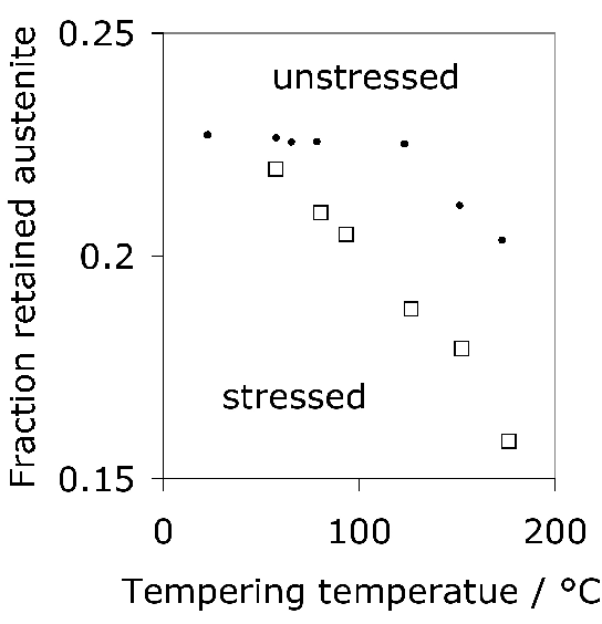
Water Rinsing
In order to mitigate thermal shock, 52100 category steels are often quenched into warm oil at 50 °C. It is found that the retained austenite content is reduced when the components are, after oil quenching, rinsed immediately in water at 15–20 °C. The water rinsing leads to an initial reduction in the content of austenite, but the results in Figure 102 do not show other significant differences in the kinetics of decomposition during isothermal heat treatment.
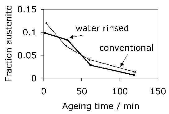
Mechanical Stability
There are two aspects to the mechanical behaviour of retained austenite: its susceptibility to ordinary plastic deformation and its response to stress- or strain-induced martensitic transformation. Demonstration has shown that the austenite in 52100 type steel is relatively soft and hence, in the composite microstructure, undergoes microscopic plastic deformation during the early stages of straining, resulting in an overall reduction of the elastic limit [609].
Martensite is triggered when the chemical free energy change \(\Delta G^{\gamma\alpha} \) achieves a critical value \(\Delta G_{M_S} \). Since martensitic transformation causes a deformation, it can also be stimulated by applying an external stress. The mechanical free energy \(\Delta G_{\text{MECH}} \) due to the interaction of the stress with the shape deformation is given by [795]:
where \(\sigma_N \) is the stress component normal to the habit plane, \(\tau \) is the shear stress resolved on the habit plane, and \(\delta \) and \(s \) are the respective normal and shear strains associated with transformation. This means that when a bearing steel is put into service, the imposed stresses may stimulate martensite to form. For example, in quenched and tempered molybdenum-modified 52100 steel, recorded strains are less than the 0.2% used to define proof strength and occur at rather small stresses.
For the data illustrated in Fig. 103, the magnitude of ΔGγα at Ms is 1415 J mol−1. That of ΔGMECH for a uniaxial tensile stress of 500 MPa can be estimated to be a maximum of 430 J mol−1 and when this stress is uniaxial compression, 290 J mol−1. The mechanical driving force is therefore rather small compared with the chemical component so it is unlikely that there would be strong variant selection [789]; in such circumstances, the transformation strain will be close to isotropic and will reflect the volume change component only. In both cases, the mechanical driving force assists the formation of martensite because the shear component of strain overwhelms the much smaller dilatational term.
It has been argued, on the basis of austenite contents measured using two different X-ray line intensities ({002}γ and {022}γ planes), that during the application of stress, the rate of austenite transformation is a function of the crystallographic orientation of the austenite grains. While it is true that there must be some dependence of the influence of stress on the austenite orientation [789], the reason for obtaining different Vγ for the 002 and 022 diffraction peaks may well be the existence of texture, in which case it is not appropriate to calculate two different retained austenite contents, but rather to take the weighted average intensities of different peaks and estimate a single Vγ [763].
That the stresses associated with the plasticity (Fig. 103) are small is a reflection of the fact that the deformation is due to martensitic transformation of retained austenite rather than ordinary plasticity involving slip dislocations. Indeed, it is found in compression experiments on quenched and tempered 52100 steel that most of the retained austenite present in the initial microstructure decomposes into martensite at strains less than 0.05 [801].
| Transformation | s | δ |
|---|---|---|
| Martensite | 0.24 | 0.03 |
| Bainite | 0.22 | 0.03 |
| Widmanstätten ferrite | 0.36 | 0.03 |
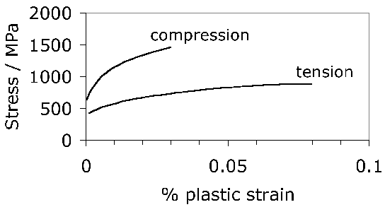
The changes in retained austenite content of the steel as a function of fatigue loading with a stress amplitude of 1500 MPa have also been studied [29], Table 22. Much of the austenite decomposes in the first cycle of fatigue. When the very first part of the cycle begins with compression, the retained austenite content hardly changes, because the stress then acts against any volume change due to transformation. It is also interesting that changes in γr following the first cycle are minimal, presumably because of mechanical stabilisation [804, 805, 807, 806, 803, 802, 809, 808, 810] and due to the refinement of the remaining austenite, which has the effect of reducing the Ms temperature [814, 815, 812, 811, 813].
| Number of cycles | γr (experiment 1) | γr (experiment 2) |
|---|---|---|
| 0 | 11.7 | 11.0 |
| ½ Compression | — | 10 |
| 1 | 3.1 | 4.7 |
| 50 | 3.7 | 11.0 |
Mechanical Stabilisation
There is a peculiar effect where the plastic deformation of retained austenite can either make it stable or unstable with respect to martensitic transformation. It is nucleation which limits the formation of martensite [818, 817], so the introduction of deformation-induced defects can accelerate transformation. However, the interface connecting martensite and austenite has a dislocation structure which is glissile; any obstacles placed in its path will hinder the progress of the transformation. A sufficiently large density of defects in the austenite can completely suppress the transformation, a phenomenon known as mechanical stabilisation [804, 802, 803]. The term "sufficiently large" is in the context of the free energy difference driving the γ → α′ change; if the magnitude of the latter is large, then the onset of mechanical stabilisation occurs at a larger number density of defects [809].
The defects that lead to stabilisation can be induced by the transformation itself; thus, bainite plates stop growing before they impinge hard obstacles because of the plastic collapse of the surrounding austenite [809, 819]. There is one study published on 52100 steel in which the formation of isothermal martensite creates defects which mechanically stabilises the remaining retained austenite to further transformation [820, 194].
Magnetic Stability
Ferrite is ferromagnetic under ambient conditions in low-alloy steels, whereas austenite has rather complicated magnetic properties but on average can be regarded as non-magnetic. This means that the transformation of austenite is accelerated (i.e. there is a rise in the martensite-start temperature) when it occurs under the influence of an external magnetic field [822, 823, 821]. Equation 40 would then suggest that the amount of austenite retained at ambient temperature should decrease. However, there are some odd results reported for 52100 steel where the application of magnetic fields during heating to the austenitisation temperature led to changes in the retained austenite content, Fig. 104. The changes observed, although consistent, are rather small and possibly within the experimental error associated with retained austenite measurements. Other experiments indicated significant improvements in the fatigue properties; this subject needs further investigation.
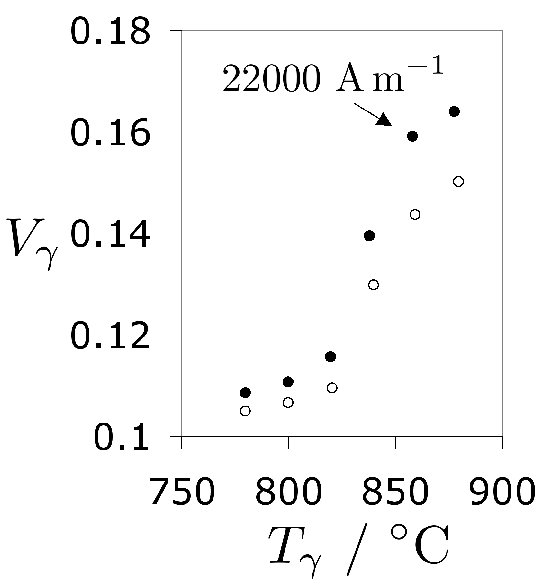
Figure 104: Fraction of retained austenite as a function of the austenitisation temperature. The circles and dots represent experiments where there was a zero and finite magnetic field applied respectively, during the heating of the steel to the austenitisation temperature. Data from [824].
Dimensional Stability
Changes in component dimensions are attributed to a large variety of phenomena, many of which have been described by Mayr [825]. The key aspects covered in various parts of this review are summarised in Fig. 105, and specific issues relating to microstructure discussed in this section.
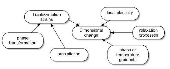
Figure 105: A summary of the dimensional changes described in this section.
The dimensional changes that occur as a consequence of alterations in microstructure can be significant when considered, for example, in the context of the tolerances associated with fitting bearings on shafts. The first precipitate to form during the tempering of martensite between 50–150 °C in the 52100 steel is ε-carbide which causes negligible shrinkage [791], the strains typically being less than 10−4 [826]. It is the volume expansion due to the decomposition of retained austenite that dominates dimensional change, with some compensation due to shrinkage if the conditions are appropriate for the precipitation of cementite (Fig. 106). The observed strain is about 10−3 per percent of retained austenite that decomposes in a 52100 type steel.
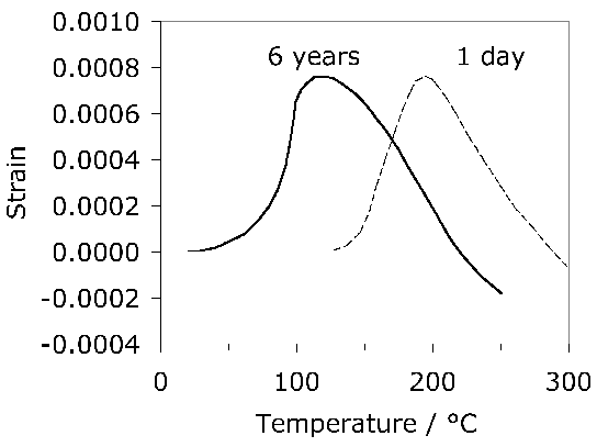
Given a detailed knowledge of the quantities, chemical compositions and densities of the phases that occur in steels, it is in principle possible to calculate the changes in size that occur when steel is subjected to heat treatment [827, 831, 830, 828, 829]. Similar work has been done in the context of bearing steels, in an attempt to relate observed dimensional changes to those due either to phase transformation or due to tempering reactions [220, 832, 833]. The problem is relatively simple when describing isotropic strains due to the transformation of a single phase, for example, the case where retained austenite decomposes into a mixture of cementite and ferrite. The complexity increases dramatically when discussing tempering, which in practice involves many reactions occurring simultaneously, so that somewhat arbitrary assumptions must be made in dividing the decomposition into separable stages. A comparison between calculations and observations then inevitably requires a level of fitting to the experimental data. For example, in the most recent work on 52100 steel [220] it is assumed that carbon is more stable in cementite than at dislocations whereas it is known that the introduction of dislocations causes the dissolution of cementite [834].
The decomposition of retained austenite into martensite, either under the influence of stress or when the steel is cooled below ambient temperature, must lead to dimensional changes given that the density of the parent phase is greater than that of the product. The resulting expansion is of the order of 4 μm per 100 mm [835]; this of course is a much smaller strain than expected if a fully austenitic 52100 steel were to transform into martensite [836]. Such changes have been measured for bearing steels and although the heat-treatment conditions were not fully reported, the strain increases as the transformation is suppressed to lower temperatures [832]. This is because the difference in density increases for transformation at lower temperatures since the thermal expansion coefficient of austenite is much greater than that of ferrite. However, this change has been demonstrated to be much smaller than the distortion that occurs during quenching [23]. Nevertheless, for bearings which are in service, the transformation of austenite can lead to a change in clearance [769], which in turn can alter the state of stress [32]. The transformation product is untempered martensite; this may or may not embrittle the steel depending on the scale of the region of austenite available for transformation [223, 222]. Fine particles of untempered, high-carbon martensite do not crack because of the difficulty in transferring stress over small length scales [236].
The magnitude of the volumetric transformation strain is illustrated in Fig. 107a, for a carburised steel which initially contains about 35% of retained austenite, when subjected to fatigue by axial loading (R = −1), as a function of the test temperature. The volumetric transformation strain decreases as the test temperature is increased primarily because the thermodynamic stability of the austenite increases and it becomes less susceptible to stress-induced martensitic transformation.
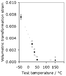
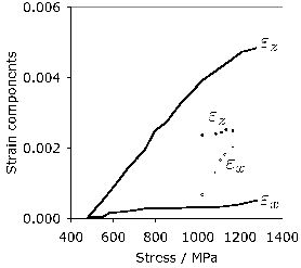
Figure 107: Strains due to transformation of retained austenite in a through-carburised steel initially containing 35% of the austenite (data after Neu and Sehitoglu [35]). (a) Volumetric transformation strain as a function of the temperature at which the sample is subjected to axial fatigue loading with R = −1. (b) Anisotropic transformation strains, along the tensile axis (εz) and along the diameter (εy) of axially loaded samples. The curves represent a tensile test and the points, results from a fatigue test. The lowest-stress points correspond to the first loading cycle, and the highest stress points to the eighth loading cycle.
The transformation strains need not be isotropic if there is a bias in the crystallographic variants of martensite or bainite that form [761, 839, 838, 789, 837]. This is because the formation of each plate causes both a shear (≈ 0.26) and dilatational strain (≈ 0.03) [100]. Each austenite grain can transform into 24 variants and if all of these form then the shear strain is effectively cancelled on a macroscopic scale in a polycrystalline sample. It is only if an applied stress or other external field favours the formation of particular plates which comply better with the field, that the microstructure becomes biased and the shear strains manifest themselves, leading to anisotropic transformation strains (Fig. 108). Transformation strains which vary with the orientation relative to the stress axis have been reported for a carburised bearing steel initially containing a large quantity of retained austenite [35]. The austenite partly decomposed into martensite during fatigue testing with elongation along the tensile axis and contraction along the other orthogonal axes.
Given the anisotropy in plasticity when phase change occurs under the influence of an external stress, it is not appropriate to represent the transformation plasticity in terms of a single parameter as is sometimes done [840]. The stress particularly favours the development of a non-random structure when the transformation mechanism is displacive (Widmanstätten ferrite, bainite, martensite) and hence the anisotropy. With individual plates of martensite and bainite, both the volume change and shear strain are not isotropic. Thus, a longitudinal strain of about 0.02 was observed when 52100 steel was transformed into martensite whilst exposed to a tensile stress of about 250 MPa [840]. This is large and inconsistent with volume strain on its own; it is a reflection of the fact that the martensite that develops will not be randomly oriented.
Fig. 107b illustrates the anisotropic transformation strains when a carburised steel initially containing 35% retained austenite is loaded in tension; the corresponding data when the sample is fatigue loaded are shown as points. It is why the anisotropy is much smaller during fatigue loading, and why εz and εx become almost equal after eight cycles of fatigue loading.
The general influence of retained austenite when subjected to fatigue loading at a variety of temperatures is summarised in Fig. 109. The athermal part is simply the transformation strain when the steel is quenched from the austenitisation temperature to ambient. The stress-affected transformation is the next stage, with the strain decreasing as thermodynamic stability of the retained austenite increases with test temperature. However, at sufficiently high temperatures, the retained austenite becomes thermally unstable and transforms into bainite, introducing the time-dependent component of strain. It is known that all of the austenite retained in 52100 steel quenched from temperatures in the range 800–850 °C is decomposed by tempering at 260 °C or above [182].
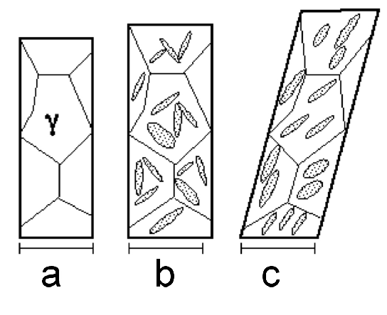
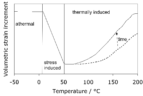
Plastic deformation can lead to a decrease in density when accompanied by the creation of defects such as dislocations. However, in a comparison of martensitic and bainitic bearing-steel 100CrMnMo8 (Table 1), these changes have been shown to be small when compared with those associated with the decomposition of retained austenite [216].
Uneven Temperature Distribution
The deviation of the dimensions and shape of a bearing component during the course of manufacture adds considerably to the expense of manufacture, so it is not surprising that the subject is well rehearsed and there exist long lists of factors which influence the distortion [841]. The focus here is on the distortion due to the variation of temperature with position within the component, which may or may not be influenced by phase transformations.
The uneven distribution of mass during heat treatment leads to variations in cooling rate across the component. This can in principle be minimised by adjusting the quenching conditions such that the product of the dimensionless quantities, the Fourier number and the Biot number, is kept constant over the geometry of the component [842]. A small Fourier number corresponds to a larger amount of heat stored in the workpiece, i.e. a greater mean temperature. The Biot number indicates the relative roles of heat transfer by thermal conduction and across interfaces; it can therefore be altered by varying, for example, the quench medium.
The temperature distribution can also become heterogeneous when dealing with large components of uniform shape when they must be cooled rapidly. Different parts of the sample do not transform at the same instance of time so that the transformation strains are not synchronised as a function of location within the specimen. It follows that anything which reduces the temperature gradients within the sample helps minimise distortion. This is illustrated in Fig. 110 which shows experiments in which a cut asymmetric ring is heat-treated in different circumstances. The difference in the gap before and after heat-treatment is taken as a measure of distortion [23]. Water quenching leads not only to the highest distortion but also the most erratic behaviour, because of the formation of a vapour blanket and the collapse of the vapour envelope before conduction and convection take over. This is not the case with oil as the quenching medium. The distortion also decreases when the temperature of the quenching medium is reduced.
Martempering involves quenching the component, usually into a salt bath, to a temperature which is just above that at which martensite forms [843]. It is then held at that temperature for a time period during which the austenite remains untransformed, in order to allow the thermal gradients to homogenise, followed by air cooling through the martensite transformation temperature range. Martempering is associated with the smallest distortion of all the methods illustrated in Fig. 110.
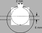
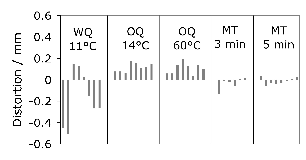
Figure 110: (a) Sample, 12 mm thick, inner and outer circle diameters 17 and 25 mm respectively, used to assess distortion. (b) WQ and OQ represent water and oil quenching to the temperatures indicated, and MT describes martempering at 200 °C. The steel used is SUJ-2 (Table 1). After Adachi [23].
Stress Relaxation
Stresses which exist over long distances cannot readily be relieved without heat treatment that promotes long-range atomic diffusion. It is surprising therefore that experiments conducted on split rings made from 52100 steel, which are elastically stressed by inserting wedges into the split [844], indicate that there are substantial changes during tempering even at low temperatures, Fig. 111. Dislocation rearrangements and carbon migration are feasible even at room temperature and lead to an increase in the yield strength by making the material more mechanically homogeneous [845]. However, these are probably insufficient to cause substantial changes in imposed stress, which is said to be related to structural changes within the material, although direct evidence is lacking. The extent of relief increases with the carbon concentration of the martensite; it is postulated that the volume changes associated with carbide precipitation cause plasticity and hence stress relief [846]19. There may be a role of other transformation strains—for example, a significant shear strain component which acts to relieve applied stresses by favouring precipitation of those crystallographic variants of carbide which accommodate the stress [847].
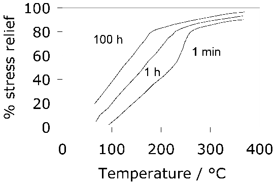
Contact Plasticity
When bearings are subjected to heavy loads, plasticity occurs at the contact surfaces causing the formation of shallow grooves which can develop into significant damage [848]. This phenomenon is often studied by assessing the ability of the steel to withstand static contact loads. The presence of austenite can exasperate the effect if it leads to a reduction in the yield strength. This is illustrated for 52100 steel in Fig. 112, where it is seen that the softening caused by the presence of austenite leads to deeper grooves. The 0% Vγ curve shows that the main factor controlling the depth of grooves is the macroscopic hardness, rather than the detailed microstructure. One aspect which is not clear is whether it helps when the austenite undergoes a stress or strain-assisted transformation into hard martensite.
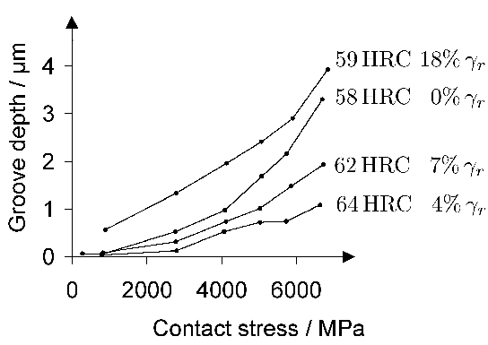
Wear Debris and Retained Austenite
In the majority of applications, the wear of bearing races is not a life-limiting factor given good lubrication and adequate surface finishing [850]. It is when the lubrication fails or when particles are introduced by contamination or detachment from the bearing that wear becomes an issue. Small spheres (≈ 8 μm diameter) which are iron-rich form, but their origin is not clear [853]. There may be debris from non-ferrous components, such as cages, or large ferrous particles (≈ 20 μm) from spalling.
Wear debris creates indentations that exacerbate fatigue damage; its detrimental influence can be mitigated by enhancing the fatigue resistance of the bearing steel, and by allowing some plasticity at the surfaces to accommodate the debris without causing sharp stress concentrations. Retained austenite is found to be beneficial in this respect [855]. The austenite is more amenable to initial deformation and work done by the debris can cause it to undergo stress or strain-induced transformation into hard martensite [118, 391]. Fig. 113 illustrates artificial indents into hardened 52100 steel. The lip profile is smoother when the steel has a larger quantity of retained austenite [160].
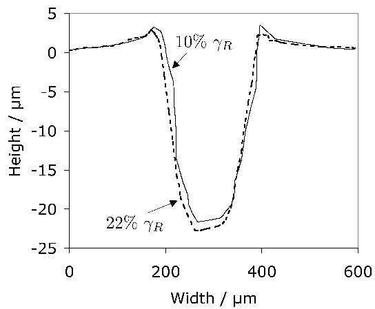
Large localised strains capable of inducing the austenite to transform into hard martensite lead to an improvement in indentation resistance. One difficulty in exploiting this is that transformation causes dimensional changes which may reduce the efficacy of an interference fit. The suggestion that Vγ should be greater than 0.05 to enhance indentation resistance must at this stage be regarded as unproven, though many studies demonstrate the benefits of retained austenite in the presence of debris damage.
Microstructural Damage
Steels in the 52100 category are partially austenitised and, after quenching, achieve a microstructure which is a mixture of undissolved cementite, untempered martensite and a small amount of retained austenite. The martensite is then tempered in the range 160–250 °C. The martensite plates are fine, approximately 0.2 μm in thickness and although they contain dislocations, electron diffraction patterns from the plates are reasonably sharp and distinct, Fig. 114. This initial microstructure changes when subjected to contact fatigue, with dramatic alterations detectable in the zone subjected to the largest shear stresses. The changes have conventionally been observed using optical microscopy and hence a terminology has evolved, based on the contrast that develops relative to the unaffected steel when the sample is etched with nital; picric acid based etchants are not effective in revealing this form of damage [859]. The so-called dark-etching regions evolve first and white-etching bands develop within these darker areas.
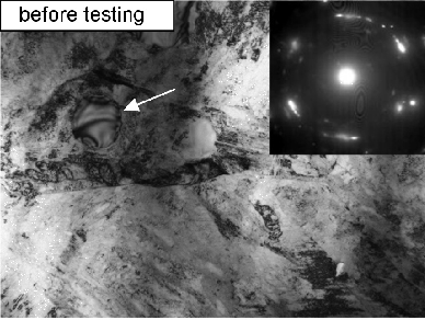
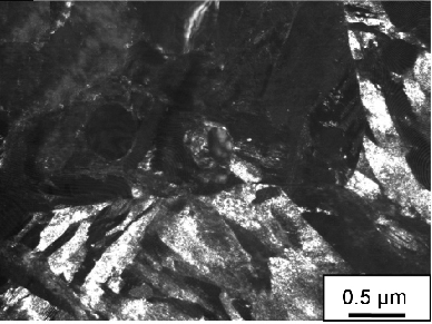
Dark-Etching Areas
In high quality 52100 type steels, rolling contact loading causes a subsurface region approximately 0.3 mm in depth to appear relatively dark when an etched sample is observed in an optical microscope; i.e., relative to the unaffected steel [860, 705]. The effect is observed typically after a few million cycles of contact. The region is dark relative to the virgin microstructure which remains at greater depths; its upper boundary is well-defined whereas the lower regions are diffuse, Fig. 115a,b. The contrast arises because the structure is heterogeneous on a fine scale, consisting of severely deformed bands separated by largely unaffected tempered martensite [741, 705, 859]. The nital etchant preferentially attacks the deformation bands leaving deep grooves which results in the dark contrast.
The depth at which the dark-etching area is created varies according to the loading conditions [861] but is generally centred around the position of maximum shear stress [741, 8]. Electron diffraction patterns from this zone reveal a greater spread in orientations, and transmission electron micrographs show that the original plates of martensite are deformed, containing significant misorientations almost in the form of cell structures [862, 863]. The large cementite particles are not significantly affected, but fine carbides apparently dissolve in the process of cyclic deformation [862], re-precipitating elsewhere, likely as ε-carbide [864].
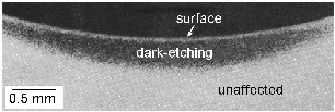
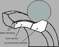
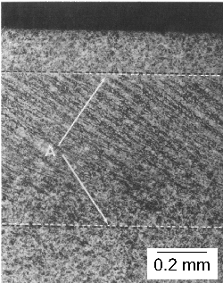
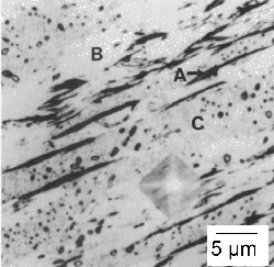
Figure 115: (a) Dark-etching region formed after 107 rotations. (b) Schematic of damaged microstructure. (c) Dark-etching region 'A'. (d) Components: 'A' cementite discs, 'B' cell ferrite, 'C' mixture of ferrite and original martensite. Micrographs (a) courtesy of T. B. Lund; (c,d) Springer Science and Business Media [741].
The dark-etching region is sometimes said to be an over-tempered form of the virgin microstructure, softening to 53 HRC from 61 HRC [865, 705]. Rearrangement of dislocations into cell structures under cyclic deformation (cyclic softening) leads to a reduction in dislocation density [867] and unpinning from carbon atmospheres [868].
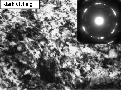
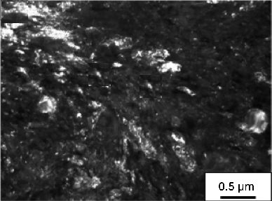
Figure 116: Dark etching region located 0.25 mm below surface after 4.3 million cycles. (a) Bright field TEM showing cell ferrite. (b) Dark field image. Micrographs courtesy of N. Mitamura.
White-Etching Regions
Bands
These areas develop within the dark-etching region during prolonged contact. They etch white or light grey because the structure is finer than optical resolution. There are high-angle bands (HABs), steeply inclined to the surface, and low-angle bands (LABs), Fig. 117.
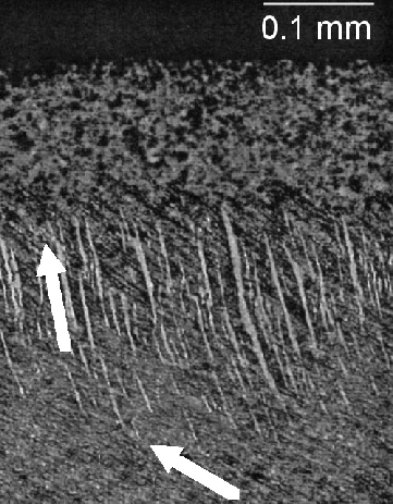
Figure 117: White-etching regions within dark areas. Arrows indicate high-angle and low-angle bands. Micrograph courtesy of T. B. Lund.
Localised deformation is so intense that dynamic recrystallisation occurs, leaving fine equiaxed grains (~20 nm) [30, 863], Fig. 118. Recrystallisation during rolling contact at 55–90 °C suggests a large driving force and possible adiabatic heating. Evidence shows carbon redistributes from the white bands to adjacent regions [879].
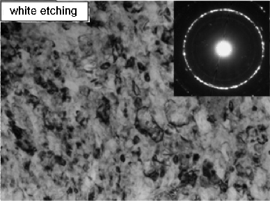
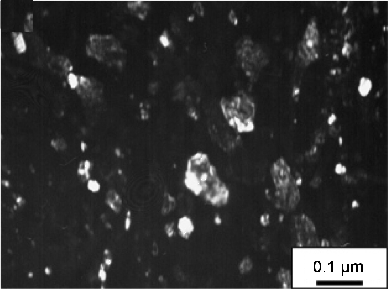
Figure 118: White-etching region showing an apparently equiaxed, recrystallised grain structure. Micrographs courtesy of N. Mitamura.
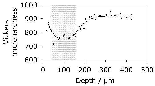
Figure 119: Microhardness as a function of depth. The shaded region shows where white bands form. Data from [877].
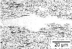
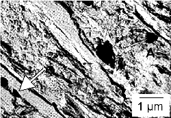
Figure 120: Optical micrographs of white-etching layers. (a) Layer free from carbides. (b) Partly dissolved carbide particle (arrowed). Reproduced from Swahn et al. [19].
It is important to distinguish between hard white regions (sections 21.2.2 & 21.2.3), formed by rubbing fractured surfaces, and soft white bands, which are carbon-depleted ferrite not necessarily associated with cracks.
The orientation of banding is a function of deformation history; reversing the direction of rolling contact can change the orientation of the bands [871].
Finite element simulations have revealed a strong correlation between the angular orientation of concentrated plastic activity and that of experimentally observed white-etching bands in rolling contact fatigue, Fig. 121. The physical mechanism for the development of the two orientations is related to the fact that the principal axes of the stress and strain rotate as the rolling element translates over the substrate; the equivalent strain increments are maximum at the particular orientations associated with the white-etching bands. The same models, however, indicate equal plastic activity in conjugate orientations (i.e. ±30° and ±80°) [887]. This is inconsistent with observations in which only one set of orientations is seen, but the discrepancy may be accounted for by the failure to consider the deformation history.
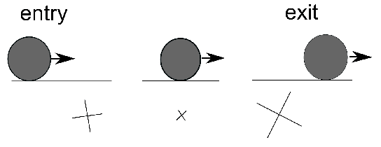
Figure 121: Principal shear strain increments indicated by crosses, as a rolling element traverses a point below the surface. The magnitudes are indicated by the size of the crosses which also show the orientation of the planes on which the plastic activity is most concentrated. Adapted from [887].
Whereas the structure of the white-etching bands is fairly well understood, it is not clear why deformation localises, and often results in patterns of layers. Whereas nucleation on defects or foreign particles can explain their distribution, the fact that the plasticity is confined to layers implies processes which lead to local softening, and frankly, there seems to be little understanding of the processes leading to softening.
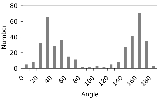
Figure 122: Apparent angles between white-etching layers and the direction in which rollers move. The distribution is bimodal, referred to as high-angle (HAB) and low-angle (LAB) bands. Data due to [30].
In general, the formation of white-etching regions is suppressed in the dark-etching areas, possibly because the formation of the latter acts to homogenise stresses. However, the two types of structures can overlap if the white-etching areas are induced first, to be engulfed later by the gradually developing dark-etching regions [862].
Rails and Machined Surfaces
White-etching surface layers are common on railway tracks where rolling-contact and sliding damage occurs, on machined surfaces and in general where steel surfaces rub together [888]. The discussion on this has focussed on whether the interaction between the wheel and rail leads to temperatures sufficiently high to austenitise the steel, in which case the white-etching layer might consist of severely deformed martensite; the alternative is that the initial microstructure is mechanically alloyed to produce carbon-supersaturated ferrite.21 The white-etching character comes from the fine scale of the structure which is homogeneous relative to the virgin material.
The so-called hard turning process involves the machining of hardened bearing steel as an alternative to grinding operations. Machining operations like these, with worn cutting tools, lead to high cutting temperatures and hence to white-etching layers which have been proven to be the result of austenitisation followed by partial transformation into martensite (the residue being retained austenite) [891, 892]. Under equilibrium conditions and at ambient pressure, the lowest temperature at which austenite appears in this alloy is 720 °C (Fig. 4). A processing map illustrating the domains of different combinations of thermal and severe plasticity is illustrated in Fig. 123.
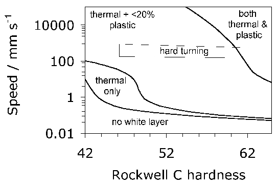
Figure 123: Processing map showing the nature of the white-etching layers formed during machining of 52100 type steel as a function of the initial hardness and cutting speed. Adapted from [217].
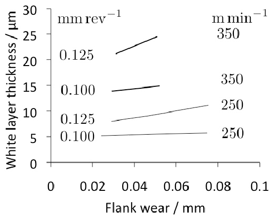
Figure 124: Variation in white-etching layer thickness on 52100 steel machined using a PCBN tool, as a function of flank wear, feed rate (mm rev−1) and cutting velocity (m min−1) [899].
The grinding of hardened bearing steels leaves a white-etching layer at the surface with a hardness in excess of 900 HV and in a state of tension (≈ 600 MPa) with penetrating microscopic cracks where the layers are thick [902]. It can reasonably be concluded that standard turning and grinding leave surfaces in compression, but when they lead to white-etching layer formation, they leave tensile residual stresses.
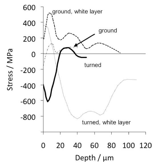
Figure 125: Stress distributions in 52100 steel as a function of depth in a hard-machined or ground condition. Data from [892].
Butterflies
The so-called butterfly wings (Fig. 126) initiate at voids, non-metallic inclusions, carbides or microcracks in steel subjected to rolling contact fatigue [374]. Voids are more susceptible to butterfly formation, followed by debonded or cracked inclusions. Manganese sulphide particles encapsulated in oxides are the most common butterfly initiation sites in modern steels, Fig. 127.
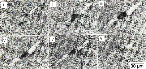
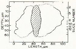
Figure 126: Three-dimensional morphology of a butterfly in steel damaged by rolling contact fatigue. (a) Serial sections as a function of depth. (b) Extension into the bearing. Reproduced from [90].
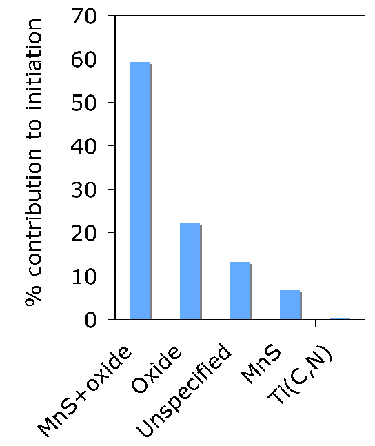
Figure 127: Particles at which butterflies initiated in an aluminium-deoxidised 52100 type steel [127].
With low contact stresses, damage is perceptible at about 5–10% of the expected L10 lifetime. The presence of butterflies does not in itself reflect traumatic failure; unfailed bearings can contain a high density of bands within their stressed volumes [612].
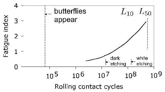
Figure 128: Damage sequence in a ball bearing. Arrows mark the appearance of dark and white-etching constituents. Adapted from [118].
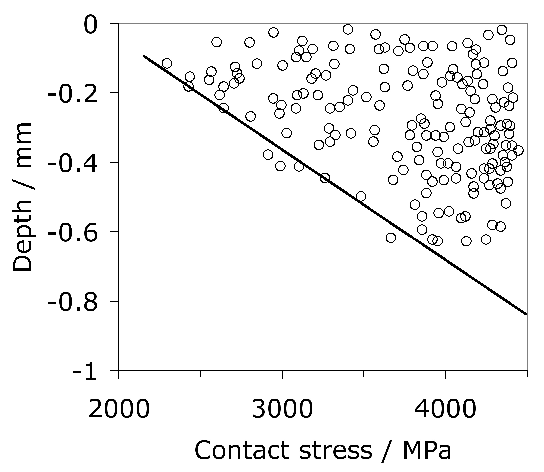
Figure 129: Shear stress as a function of depth. The line defines depths where shear stress reduces to 400 MPa, marking the observation of butterflies [127].
The hardness within the wing can exceed 1000–1300 HV. The intensity of deformation leads to a structure divided into minute grains (5–50 nm in size) in random orientations [50]. This structural refinement is often attributed to dynamic or static recrystallisation at temperatures near ambient, assisted by the high defect density.
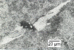
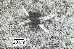
Figure 130: Orientation of butterfly wings. (a) Typical butterfly. (b) Double-winged butterfly after rotating in both directions. Reprinted from [913].

Figure 131: Schematic representation of the structure of a "butterfly" wing as it appears on a section containing the over-rolling direction.
Spheres in Hard White Matter
Hard white matter contains cracks; when two such cracks are parallel, the shearing action fragmentation of the intervening matrix can roll fragments into spheres, as illustrated in Fig. 132.
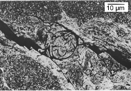
Figure 132: A spherical particle of white matter between approximately parallel cracks [909].
Solidification-induced White-etching Bands
Very large white-etching bands have been observed on the scale of continuously cast billets in 52100 steel [919]. These are caused by electromagnetic stirring, leading to a carbon-depleted zone near the centre of the casting.
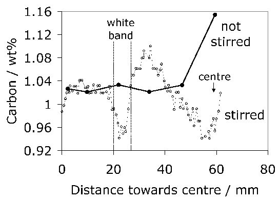
Creep
The term "creep" is used here in a general sense where thermally activated deformation occurs as a function of time at stresses below the yield strength as measured in a tensile test. The observed strain is not necessarily associated with the diffusion of large atoms or dislocation climb. The process might be described better as relaxation.
Creep at low homologous temperatures is thermally activated and attributed to two possible mechanisms: (i) dislocation glide; (ii) time-dependent phase transformation or twinning plasticity. In the former case, the strain increases logarithmically with time and involves either the work-hardening of barriers to dislocation glide, or the gradual exhaustion of weaker barriers [920].
The second mechanism is a consequence of transformation strains [921], due for example to the volume change accompanying the change in crystal structure, or shear strains due to displacive transformations. The strain still varies with the logarithm of time and is thermally activated, but the time-dependence of phase transformation can be less clear at the low homologous temperatures involved. It has been suggested, although there is little direct evidence, that in 52100 steel which is quenched and tempered25, the coarsening of transition carbides of iron leads to plasticity involving the diffusion of carbon atoms from dissolving to growing particles [922]. This leads to a logarithmic variation in strain with time although the details are not established. It is feasible, however, that coarsening occurring under the influence of an external stress may lead to a Greenwood-Johnson type [923] transformation plasticity effect which manifests as time-dependent creep. The strain recorded is very small indeed, Fig. 134.
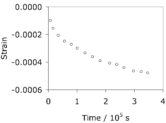
Case-Hardened Bearings
The term "through hardening" implies that the entire component is produced in the martensitic state. This may not be necessary in large components where the heavily loaded regions form a small fraction of the body of the material. Untempered high-carbon martensitic steels can achieve a maximum hardness of about 800 HV [223] but the dissolved carbon tends to make the martensite brittle. One solution is to use a low-carbon steel but to diffuse a larger concentration into the surface which is then transformed into hard martensite, in a process known as case-hardening. This typically gives a strong, wear-resistant layer with a hardness of about 750 HV [925, 924], but the surface itself still lacks ductility. The limiting factor is in fact the static load carrying capacity. Nevertheless, having a tough, unhardened core supporting the working volume of the bearing raceway has advantages, and in some cases hybrid bearings with ceramic rollers running on case-hardened raceways outperform through-hardened steel versions [601].
It is worth emphasising that the case and its mechanical property profile must be designed so that a hardness of about 60 HRC is maintained to beyond the depth where the stresses which do the greatest damage occur [284]. Fig. 135 illustrates that a Hertzian pressure of 4000 MPa could not be tolerated given the strength profile produced in a case-hardened bearing steel.
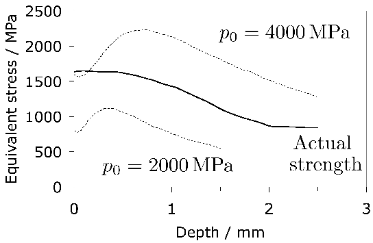
Case-hardening has an advantage in the context of bearings because it results in the development of compressive stresses which extend at least to the depth of the case. This is because the martensite-start temperature of the carbon-rich case is lower than that of the core steel. The latter therefore transforms first on cooling, and the associated transformation strain (expansion) causes the case which is still austenitic, to relax by plastic deformation. On subsequent transformation into martensite, the expansion of the case is constrained by the bulk of the core, leading to the compressive stresses, Fig. 136. It is said that the magnitude of the compressive stress is a function of the difference in the martensite-start temperatures of the case and core [161].
The stress profiles can be modified dramatically if large fractions of retained austenite persist in the case, since as already noted, it is the martensitic transformation strain that is the cause of the compressive stresses. It is not then surprising that steps taken to transform the retained austenite in carburised or carbonitrided cases lead to enhanced fatigue properties [926].
Averbach and co-workers [343, 561] undertook experiments in which both M50 NiL and CBS 1000M were carburised to a depth of 2.5 mm. Fig. 137 shows the distribution of residual stress as a function of depth for these two steels after carburising, austenitisation, and repeated refrigeration and tempering. It is noticeable when comparing against Fig. 136 that the depth of carburising has significantly altered the retained austenite content and hence the stress distribution, with smaller compressive stresses in both alloys, and worrying tensile stresses in the close proximity of the surface of the M50 NiL.
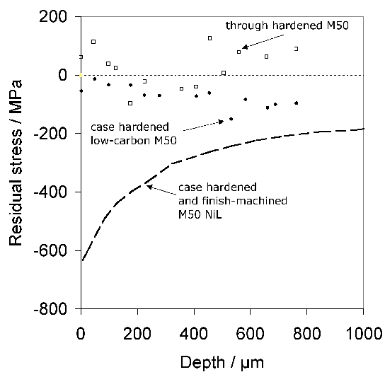
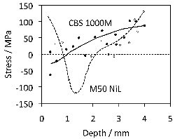
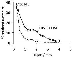
Although not in the context of bearing steels, case-carburised steel isothermally transformed at 200 °C has been shown to lead to extremely fine and hard bainite (620 HV) in the surface layer, with the transformation inducing a compressive stress of about 200 MPa into the surface [927].
Case Depth
Lai and coworkers [933] have developed a method for assessing the adequacy of the hardened layer with respect to indentation and sub-surface fatigue damage arising from the repeated application of load at the same location on the raceway, a process known as standing contact fatigue. First, the depth to which a material becomes indented is given by:
where \(\delta_I \) is the plastic indentation depth, \(D_w \) is the rolling element diameter, \(\sigma_e^{max} \) is the maximum sub-surface von Mises equivalent stress, and \(\sigma_y \) is the yield strength of the material concerned. For a case-hardened surface:
where \(\phi \) is an empirical term which partitions \(\delta_I \) into a term due to the deformation of the case and of the substrate.
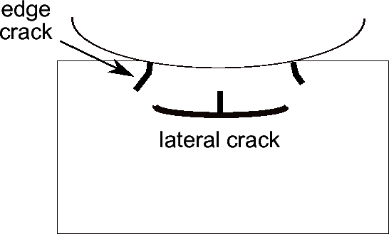
Wind Turbine Bearings
The radius of wind turbine blades has increased from 5 to 70 metres over the past 25 years resulting in an increase in power output to about 10 MW [934]. The rotation rate of the blades is such as to keep the tip velocity below that of sound in air, so mills with large blades must rotate slowly. The slow turning motion of the blades is transmitted to a gearbox via a main shaft that is supported on large bearings, Fig. 139.
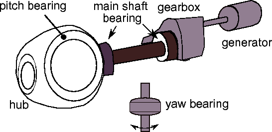
In excess of 60% of gearbox failures are attributed to bearings; although such failures are much less frequent than those associated with electrical components, they are much more expensive to repair [935]. Yaw and pitch bearings are case-hardened to about 58 HRC or induction-hardened to some 56 HRC. A change in raceway hardness from 58 to 56 HRC can reduce the \(L_{10} \) life by 30% [935, 936].
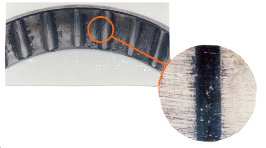
The main shaft is usually supported by spherical roller bearings because they can cope with both axial and radial loads and accommodate shaft misalignment. Experience in the wind turbine industry suggests that these bearings in particular suffer from early failure, i.e. much earlier than say the L10 life. Some of the failures are attributed to damage from wear which leads to micropitting [935]. Work on carburised gear steels indicates that the key factors other than material type influencing the development of micropits in contact experiments are surface finish, lubricant, load, temperature, speed and slide-to-roll ratio; the last two have the greatest effect on pit propagation, whereas the load is most responsible for initiation [937].
Fig. 141a shows the initial stages of such damage with two distinct wear tracks forming on the raceway. The stress concentrations resulting from the microscopic pits in this region then lead to fatigue spalling as illustrated in Fig. 141b. There is evidence that this kind of damage begins with sliding shear as opposed to rolling contact, between the rollers and raceway [935]. If this is the cause for most early failures, then the solution lies in engineering design rather than material improvements. Early work on the theory of micropitting suggests that there are three parameters which significantly influence the development of these pits [938]. The first is the contact area between the raceway and rolling element, the distance between asperities and the Stribeck parameter λ, which is the ratio of the lubrication film thickness to composite surface roughness (section 27). Pitting is diminished when the asperities are deformed elastically during the operation of the bearing.
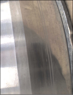
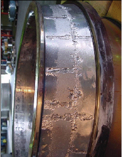
One problem with large bearing rings, such as those associated with wind turbines, is that the amount of deformation the steel experiences between the casting and the final assembly is necessarily limited. The deformation, in addition to producing the required shape, is useful in refining the structure, enhancing chemical homogeneity and breaking up inclusions. The role of deformation processing on inclusions is well-known, but recent work confirms this in the context of modern 52100 type steel, where the oxysulphide inclusions were characterised using the statistics of extreme values, and the L10 life was shown to vary by approximately an order of magnitude as a function of the reduction ratio [939]. One solution proposed a long time ago is to use deformed strip which is profile rolled into circular form and butt-welded [940]. However, there are no details available and the process does not seem to have been adopted.
Critique
The purpose here is not to reflect conclusions or derived concepts which have been stated in context, but rather, to highlight a few of the interpretations which may be helpful in defining progress or in encouraging discussion:
- Hypereutectoid bearing steels are often supplied in a spheroidised condition. One method designed to reduce the cost of the spheroidising heat treatment is to generate divorced pearlite during cooling. There is no theory currently available to balance the competition between the lamellar and divorced forms of pearlite whilst at the same time accounting for all the rate-controlling solutes present in the steel.
- Bainitic microstructures in the 52100 type steels in some respects outperform those which contain tempered martensite. Some process-related work has been done to reduce the time-scale of the heat treatments necessary to generate the strong bainite, but another unexplored approach might involve small modifications to the steel composition using established theory in order to examine the practicality of accelerating the bainite reaction.
- Chemical segregation due to solidification is a popular parameter in discussions of the relative merits of bearing alloys. There have been considerable advances in technologies aimed at reducing segregation. However, a systematic study using well-developed casting models combined with thermodynamic phase stability databases, may reveal alloys which are better suited to homogeneous solidification. The particular aspect that should be examined in such work would be the propensity to form coarse carbides in solute enriched zones.
- In comparison with the wider subject of steel metallurgy, there has been negligible work on the use of magnetic fields to control the evolution of structure, and or retained austenite in bearing steels. Some speculative work on possible benefits, in spite of obvious expense, would be stimulating.
- There is a large literature on uniaxial fatigue testing, over loading-frequencies ranging from a few Hertz to tens of kHz. The results from such tests are sensitive to specimen shape, size and surface condition. They cannot in general be used in design and the damage mechanisms are not comparable to those encountered in rolling contact fatigue. A debate on the role of such tests in the design of bearing steels would be useful. Torsion-compression tests may approximate the stress fields in rolling contact deformation, but evidence is needed to confirm that the damage mechanisms, including the formation of White matter, are similar.
- A large amount of the literature on rolling-contact fatigue experiments concerns tests which are conducted at contact stresses far greater than those experienced in service. Whilst this is understandable as a means of accelerating tests, there is strong evidence that the damage mechanisms are not identical to those responsible for L10 life.
- Whilst there is no doubt that presence of diffusible hydrogen leads to a deterioration of properties, there seems to be an overemphasis on its role in locally enhanced plasticity as the mechanism for embrittlement. The influence of hydrogen on reducing the stress required for cleavage has largely been neglected even though it is evident that macroscopic ductility is severely compromised in strong steels. There is a clear need for critical experiments to resolve these interpretations, and possibly a focus on improving the toughness of bearing steels so as to make them more resistant to hydrogen-induced effects.
- More fundamental work on the mechanical tempering of martensitic microstructures would be useful in understanding the formation and control of dark-etching zones.
- There is a missing factor in mathematical models of White matter evolution during rolling contact fatigue. Whilst the orientation of bands has been correlated with finite element models, the factors which lead to the localisation of strain localisation that is necessary for this kind of structural change, do not feature in any model. There is therefore no way of estimating either the frequency, size or shape of the bands. Experiments designed to test or alter these parameters are similarly lacking.
- The toughness of 52100 type steels is a relatively neglected property when it comes to the development process. There is evidence that impurities such as phosphorus play a role in embrittling the austenite grain boundaries. Failure at these boundaries is obvious in fractographic observations of rolling contact fatigue experiments. Microcracking resulting from decohesion at those boundaries contributes to nuclei for White matter generation in the form of butterflies. The embrittlement must, from knowledge available in the broader field of strong steels, exacerbate the detrimental influence of hydrogen.
- The Lundberg-Palmgren theory and its adaptations have been incredibly effective in representing the life of engineered bearings on the basis of experimental data. The form of the equation used is simple. Given that there is a degree of empiricism, and that the most general method for empirical analysis is the neural network, it would be useful for the industry to exploit this technique using the same data as are necessary for the current model. [941, 946, 943, 945, 944, 683, 942].
- The transformation strains resulting from the decomposition of retained austenite have largely been assumed to be isotropic. There is much work outside of the bearing steels field which suggests otherwise and more fundamental research should now be possible with the availability of techniques which simultaneously measure phase fractions, crystallography and structure. Any anisotropy would imply consequences on residual stress development.
- More research is needed on the continued use of alloys and processes which have been tremendously successful in small bearings, but are now being applied to very large bearings for arduous environments such as those being applied in windmills. History suggests that there were major breakthroughs in alloy development when the need arose for tougher aeroengine bearings. Perhaps a similar push to look at alternative alloys may prove fruitful when it comes to large bearings.
Acknowledgements
I am grateful to Professor Lindsay Greer for the provision of laboratory facilities at the University of Cambridge, and to support from the World Class University Programme of the National Research Foundation of Korea, Ministry of Education, Science and Technology, project number R32-10147.
I am especially grateful to John Beswick for giving me access to his enormous library of literature on bearings, for addressing my occasional queries, and for thorough, constructive comments on a draft of this manuscript. Many colleagues have been generous in providing me with publications and micrographs. I had interesting discussions with Professors Dong Woo Suh and Nagraj Arakere.
Appendix 1: Stribeck Curve
For the vast majority of engineering applications, bearing steels are designed on the assumption that the component in service will be reasonably well-lubricated. The Stribeck curve [38] defines three regimes of friction during lubricated rolling contact. The curve relates the friction coefficient (ratio of the normal force FN to the force of kinetic friction FF) to the ratio λ (specific film thickness ratio):
Where tfilm is the minimum oil film thickness and troughness is the composite surface roughness given by (troughness(1) + troughness(2))1/2. Aeroengine bearings are typically finished to a roughness better than 0.05 µm [314]. The parameter λ depends on relative speed, roughness, and lubricant viscosity.
Regime I: Partial contact where λ < 1. High friction due to metal-to-metal contact.
Regime II: Mixed lubrication where 1 < λ < 3.
Regime III: Full film lubrication where metal contact is avoided.
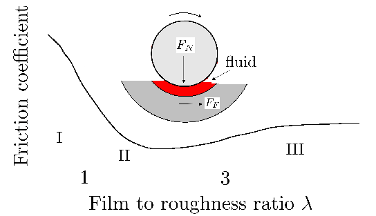
Figure 142: Different regimes of friction during lubricated rolling contact.
Appendix 2: Useful Empirical Relationships
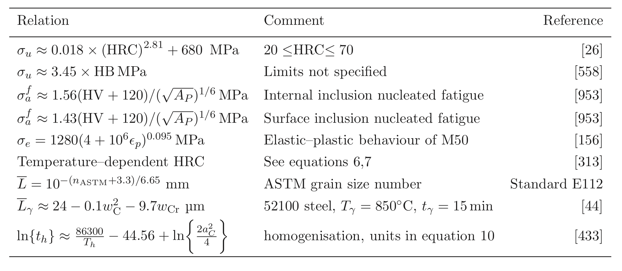 |
Bibliography
- 1
- E. V. Zaretsky.
Selection of rolling-element bearing steels for long-life applications.
In J. J. C. Hoo, editor, Effect of steel manufacturing process on the quality of bearing steels, pages 5-43, Philadelphia, USA, 1988. ASTM. - 2
- E. V. Zaretsky.
Rolling bearing steels - a technical and historical perspective.
Materials Science and Technology, 27:in press., 2011. - 3
- E. N. Bamberger.
Effect of materials - metallurgy viewpoint.
In P. M. Ku, editor, Interdisciplinary Approach to the Lubrication of Concentrated Contacts, number SP-237 in NASA, pages 409-437, Washington, D. C., USA, 1970. NASA. - 4
- H. K. D. H. Bhadeshia.
Mechanical bearings.
Technical Report https://www.phase-trans.msm.cam.ac.uk/2010/types/index.html, University of Cambridge, Cambridge, U. K., 2010. - 5
- E. V. Zaretsky, W. J. Anderson, and R. J. Parker.
The effect of contact angle on rolling-contact fatigue and bearing load capacity.
Tribology Transactions, 5:210-219, 1962. - 6
- J. Aylen.
Open versus closed innovation: development of the wide strip mill for steel in the United States during the 1920s.
R &Management, 40:67-80, 2010. - 7
- R. J. Parker, H. R. Singer, and S. I. Pinel.
Endurance tests with large-bore tapered-roller bearings to 2.2 million dn.
Technical report, NASA, Lewis Research Centre, Cleveland, Ohio, USA, 1981. - 8
- I. A. Polonsky and L. M. Keer.
On www.phase-trans.msm.cam.ac.uk etching band formation in rolling bearings.
Journal of the Mechanics and Physics of Solids, 43:637, 1995. - 9
- E. N. Bamberger.
Materials for rolling element bearings.
In W. J. Anderson, editor, Bearing Design - Historical Aspects, Present Technology and Future Problems, pages 1-46, San Antonio, Texas, 1980. ASME. - 10
- J. Cappel, M. Weinberg, and R. Flender.
The metallurgy of roller-bearing steels.
Steel Grips, 2:261-268, 2004. - 11
- F. Hengerer.
The history of SKF3.
Ball Bearing Journal, 231:2-11, 1987. - 12
- K. Tsubota, T. Sato, Y. Kato, K. Hiraoka, and R. Hayashi.
Bearing steels in the 21st century.
In J. J. C. Hoo and W. B. Green, editors, Bearing Steels: into the 21st Century, pages 202-215, Pennsylvania, USA, 1998. American Society for Testing of Materials. - 13
- Anonymous.
The effect of carbide network on the life of AISI 52100 in rolling contact fatigue.
Technical Report May 6, Federal-Mogul Corporation, Derbyshire, U. K., 1982. - 14
- P. Gembalova, J. Boruta, E. Grycz, and K. M. Cmiel.
Hot forming parameters research of bearing steel.
Archives of Civil and Mechanical Engineering, 721-28, 2007. - 15
- S. Chattopadhyay and C. M. Sellars.
Kinetics of pearlite spheroidisation during static annealing and during hot deformation.
Acta Metallurgica, 30:157-170, 1982. - 16
- S. Chakraborty.
Ball bearing steel and the role of mini-steel plants in India.
Indian Insitute of Metals News, 12:25-38, 2009. - 17
- G. T. Hahn, V. Bhargava, and Q. Chen.
The cyclic stress-strain properties, hysteresis loop shape, and kinematic hardening of two high-strength bearing steels.
Metallurgical & Materials Transactions A, 21:653-665, 1990. - 18
- S. Muramoto, H. Matsunaga, S. Moriyama, and M. Endo.
Crack size dependency of shear mode fatigue crack threshold in bearing steel.
Key Engineering Materials, 385-387:449-452, 2008. - 19
- H. Swahn, P. C. Becker, and O. Vingsbo.
Electron-microscope studies of carbide decay during contact fatigue in ball bearings.
Metal Science, 10:35-39, 1976. - 20
- G. E. Hollox, R. A. Hobbs, and J. M. Hampshire.
Lower bainite bearings for adverse environments.
Wear, 68:229-240, 1981. - 21
- V. M. Pchelkina.
Increasing the quality and properties of bearing parts by surface hardening with the use of induction heating.
Metal Science and Heat Treatment, 30:168-172, 1988. - 22
- Yu. M. Efimenko, A. B. Kuslitskii, D. V. Chaban, G. V. Karpenko, and B. A. Movchan.
Effect of electron-beam melting upon the properties of grade ShKh15 ball-bearing steel.
Soviet Materials Science, 1:333-335, 1966. - 23
- A. Adachi and Z. Morita.
On the distortion of ball bearing steel.
Technology Reports of Osaka University, 6(200):133-139, 1956. - 24
- C. M. Suh and J. H. Kim.
Fatigue characteristics of bearing steel in very high cycle fatigue.
Journal of Mechanical Science and Technology, 23:420-425, 2009. - 25
- T. Sakai, B. Lian, M. Takeda, K. Shiozawa, N. Oguma, Y. Ochi, M. Nakajima, and T. Nakamura.
Statistical duplex S-N characteristics of high carbon chromium bearing steel in rotating bending in very high cycle regime.
International Journal of Fatigue, 32:497-504, 2010. - 26
- K. Tosha, D. Ueda, H. Shimoda, and S. Shimizu.
A study on P-S-N curve for rotating bending fatigue test for bearing steel.
Tribology Transactions, 51:166-172, 2008. - 27
- Y. Matsubara and H. Hamada.
A novel method to evaluate the influence of hydrogen on fatigue properties of high strength steels.
In J. M. Beswick, editor, Bearing Steel Technology - Advances and State of the Art in Bearing Steel Quality Assurance, pages 153-166, West Conshohocken, PA, USA, 2007. ASTM International. - 28
- J. M. Beswick.
Steel with a composition of iron, carbon, phophorus and molybdenum.
Technical Report US Patent 4,961,904, U. S. Patent Office, 1990. - 29
- H.-J. Christ, C. Sommer, H. Mughrabi, A. Voskamp, J. Beswick, and F. Hengerer.
Fatigue behaviour of three variants of the roller bearing steel SAE 52100.
Fatigue & Fracture of Engineering Materials & Structures, 15:855-870, 1992. - 30
- H. Harada, T. Mikami, M. Shibata, D. Sokai, A. Yamamoto, and H. Tsubakino.
Microstructural changes and crack initiation with www.phase-trans.msm.cam.ac.uk etching area formation under rolling/sliding contact in bearing steel.
ISIJ International, 45:1897-1902, 2005. - 31
- D. E. Diesburg, D. V. Doane, and J. L. Mihelich.
Critical alloying elements in bearing steels.
In Critical Materials in Bearings, pages 1-24, USA, 1984. Vanderbilt University. - 32
- P. Daguier, O. Roesch, and W. Trojahn.
New development in through hardened bearing steel grades for use in contaminated lubricants.
Journal of ASTM International, 3:JAl14045, 2007. - 33
- Anonymous.
Crucible 52CB bearing steel data sheet.
Technical Report 8-62, Crucible Steel Company of America, Pittsburgh, USA, 1962. - 34
- J. S. Lee.
Characteristics of vanadium alloyed carbonitrided steel for rolling bearing applications.
Journal of ASTM International, 3:JAI100422, 2007. - 35
- R. W. Neu and H. Sehitoglu.
Measurement of transformation strain during fatigue loading.
In C. Amazallag, editor, Automation in Fatigue and Fracture: Testing and Analysis, pages 581-597, Philadelphia, USA, 1994. ASTM International. - 36
- J. D. Dougherty, T. S. Srivatsan, and J. Padovan.
Cyclic stress response, strain resistance and fracture behavior of modified 1070 steel.
Engineering Fracture Mechanics, 53:829-847, 1996. - 37
- P. V. Dimitry, P. J. McDonough, G. Beck, R. Eberhard, and H. W. Zock.
Development of 5280 rolling bearing steel for improved performance and productivity.
In J. M. Beswick, editor, Bearing Steel Technology, pages 3-26, Pennsylvania, USA, 2002. ASTM. - 38
- M. Woydt and R. Wäsche.
The history of the Stribeck curve and ball bearing steels: The role of Adolf Martens.
Wear, 268:1542-1546, 2010. - 39
- F. Borik and R. D. Chapman.
The effect of microstructure on the fatigue strength of a high carbon steel.
Trans. ASM, 53:447-463, 1961. - 40
- H. Chu, C. Chen, and J. Yang.
Rolling contact bearing steel for operation at 120 to 250 C.
In J. J. C. Hoo, editor, Creative use of bearing steels, pages 185-196, Philadelphia, USA, 1993. ASTM. - 41
- NPL.
MTDATA.
Software, National Physical Laboratory, Teddington, U.K., 2006. - 42
- M. Melander.
The single-shot induction hardening cycle: A computational approach.
Technical Report LiTH-IKP-R-265, Linköping University, Sweden, 1982. - 43
- C. A. Stickels.
Carbide refining heat treatment for 52100 bearing steels.
Metallurgical Transactions, 5:865-874, 1974. - 44
- J. M. Beswick.
Effect of prior cold work on the martensite transformation in SAE 52100.
Metallurgical & Materials Transactions A, 15:299-306, 1984. - 45
- R. A. Grange.
The rapid heat treatment of steel.
Metallurgical Transactions, 2:65-78, 1971. - 46
- F. Peilloud and G. Duragne.
Optimisation du traitement thermique de i'acier 100 Cr 6.
Mémoires et études scientifiques de la revue de métallurgie, 81:135-144, 1984. - 47
- A. Ray, S. Ray, and S. R. Mediratta.
Effect of carbides on the austenite grain growth characteristics in 1Cr-1C and 6Cr-1Mo-1C steels.
Journal of Material Science, 25:5070-5076, 1990. - 48
- F. Hengerer, J. Beswick, and A. Kerrigan.
Evaluation of the continuous casting method for bearing steel production-- SKF experience.
In J. J. C. Hoo, editor, Creative use of bearing steels, Philadelphia, USA, 1993. ASTM. - 49
- K. Monma, R. Maruta, T. Yamamoto, and Y. Wakikado.
Effect of particle sizes of carbides and amounts of undissolved carbide on the fatigue life of bearing steel.
Journal of the Japan Institute of Metals, 32:1198-1204, 1968. - 50
- R. Österlund, O. Vingsbo, L. Vincent, and P. Guiraldenq.
Butterflies in fatigued ball bearings - formation mechanisms and structure.
Scandinavian Journal of Metallurgy, 11:23-32, 1982. - 51
- J. M. Beswick.
The effect of chromium in high carbon bearing steels.
Metallurgical & Materials Transactions A, 18:1897-1906, 1987. - 52
- J. M. Beswick.
The effects of alloying elements in high carbon bearing steels.
Ball Bearing Journal, 231:2-11, 1988. - 53
- H. K. D. H. Bhadeshia.
Theoretical analysis of changes in cementite composition during the tempering of bainite.
Materials Science and Technology, 5:131-137, 1989. - 54
- J. B. Kelley and G. Krauss.
Effect of chromium and microstructure on the bending fatigue of 0.75Mo-1.8Ni-0.80C steels.
In Proceedings of the 4th International Congress on Heat Treatment of Materials, volume 1, pages 147-163, Berlin, Germany, 1985. Arbeitsgemeinschaft Wärmebehandlung und Werkstofftechnik. - 55
- J. Wadsworth and O. D. Sherby.
Influence of chromium on superplasticity in ultra-high carbon steels.
Journal of Materials Science, 13:2645-2649, 1978. - 56
- A. Yamamoto, K. Inoue, and H. Tsubakino.
Analysis of spherical carbides formed in chromium added hypereutectoid bearing steels.
Materials Science Forum, 539-543:4866-4871, 2007. - 57
- H. K. D. H. Bhadeshia.
The driving force for martensitic transformation in steels.
Metal Science, 15:175-177, 1981. - 58
- H. K. D. H. Bhadeshia.
Thermodynamic extrapolation and the martensite-start temperature of substitutionally alloyed steels.
Metal Science, 15:178-150, 1981. - 59
- M. Guillot and G. Dudragne.
Optimisation of the thermal treatment of a roller bearing steel 100 Cr 6.
Memoires Etudes Scientifiques Rev. Metallurg., 79:493, 1982. - 60
- J. M. Beswick.
Fracture and fatigue crack propagation properties of hardened 52100 steel.
Metallurgical & Materials Transactions A, 20:1961-1973, 1989. - 61
- Y. Hirotsu and S. Nagakura.
Crystal structure and morphology of the carbide precipitated from martensitic high-C steel during the 1st stage of tempering.
Acta Materialia, 20:645-655, 1972. - 62
- G. Hägg.
Pulverphotogramme eines neuen eisencarbides.
Zeitschrift für Kristallographie, 89:92-94, 1934. - 63
- V. H. Borchers and K. Doffin.
Kinetik der bildung des karbids Fe C in stahl 100Cr6.
Archiv für das Eisenhüttenwesen, 40:493-498, 1969. - 64
- T. L. Carter, R. H. Butler, H. R. Bear, and W. J. Anderson.
Investigation of factors governing fatigue life with the rolling-contact fatigue spin rig.
Tribology Transactions, 1:23-32, 1958. - 65
- G. Ya. Andreev, V. I. Kushakov, and I. E. Chernikova.
The effect of rapid heating on the properties of ShKh15 steel in assembling rolling bearing units.
Chemical and Petroleum Engineering, 12:809-812, 1976. - 66
- K. Z. Shepelyakovskii, A. N. Kuznetsov, and V. T. Gubenko.
Influence of low-temperature electric tempering cycles on the properties of bearing steel.
Metal Science and Heat Treatment, 25:254-257, 1983. - 67
- E. D. Scott and J. Blakewell.
The assessment of ball bearing steels of modified chemical composition.
Wear, 46:273-279, 1978. - 68
- F. R. Bonte.
Bearing steels.
Technical Report U.S. Patent 2,413,602, U. S. Patent Office, 1946. - 69
- K. M. Vedula and R. W. Heckel.
Spheroidization of binary Fe-C alloys over a range of temperatures.
Metallurgical Transactions, 1:9-18, 1970. - 70
- C. V. Darragh, J. J. Donze, and P. C. Weigel.
New bearing steel combines high hardenability, low cost.
Metal Progress, 100:74-75, 1971. - 71
- H. Brandis, F. Berentzen, S. Engineer, and W. Schmidt.
Development of a new ball bearing steel.
Härterei-technische Mitteilungen, 39:173-179, 1984. - 72
- J. D. Crawford and W. H. Chang.
Vacuum melted molybdenum steel for ball and roller applications.
Technical Report 3560A, Climax Molybdenum Company, Ann Arbor, Michigan, USA, 1963. - 73
- J. D. Crawford.
Laboratory investigation of bearing steels for service up to 500 F.
Technical Report L-225, Climax Molybdenum Company, Ann Arbor, Michigan, USA, 1964. - 74
- A. G. Allten and P. Payson.
The effect of silicon on the tempering of martensite.
Trans. ASM, 45:498-532, 1953. - 75
- A. G. Allten.
Discussion to ``the effect of silicon on the kinetics of tempering''.
Trans. ASM, 46, 812-829 1954. - 76
- W. S. Owen.
The effect of silicon on the kinetics of tempering.
Trans. ASM, 46:812-829, 1954. - 77
- G. W. Lorimer R. M. Hobbs and N. Ridley.
Effect of silicon on the microstructure of quenched and tempered medium carbon steels.
Journal of the Iron and Steel Institute, 210:757-764, 1972. - 78
- E. Kozeschnik and H. K. D. H. Bhadeshia.
Influence of silicon on cementite precipitation in steels.
Materials Science and Technology, 24:343-347, 2008. - 79
- H. Nakashima.
Trends in materials and heat treatments for rolling bearings.
Technical Report Technical Review No. 76, NTN Corporation, Osaka, Japan, 2008. - 80
- A. S. Kagan, A. G. Spektor, and R. I. Tsil'man.
Decomposition of martensite in steel ShKh15 in the process of quenching.
Metal Science and Heat Treatment, 23:691-693, 1981. - 81
- A. S. Kagan, A. G. Spektor, and R. I. Tsil'man.
Decomposition of martensite in steel ShKh15 in the process of quenching.
Metal Science and Heat Treatment, 23:691-693, 1982. - 82
- I. M. Andersson-Drugge and T. Lund.
A ferritic-pearlitic steel with eutectoid composition.
In J. J. C. Hoo, editor, Creative use of bearing steels, pages 171-184, Pennsylvania, USA, 1993. American Society of Testing Methods. - 83
- N. N. Kachanov.
Hardenability of bearing steel.
Metal Science and Heat Treatment, 4:48-51, 1962. - 84
- N. N. Kachanov.
The effect of certain factors on hardenability of ShKh15 steel.
Metal Science and Heat Treatment, 4:499-502, 1962. - 85
- R. Eberhard and O. Zwirlein.
Neue härtbarkeitsprüfmethode für stähle hoher durchhärtbarkeit.
Härterei-technische Mitteilungen, 39:152-155, 1984. - 86
- W. Hewitt.
Hardenability - its prediction from chemical composition.
Heat Treatment of Metals, 2:33-38, 1981. - 87
- R. R. Leppänen and J. Beswick.
Microalloyed steel rolling bearings.
Technical Report 6333001 B1, United States Patent, Ovaka Steel, Hallefors, Sweden, 2001. - 88
- J. M. Beswick.
SKF 3 as a structural steel for hub units.
Ball Bearing Journal, 231:32-41, 1988. - 89
- S. V. Benktander.
Automotive hub bearing units - European experience.
SAE Technical Paper Series, 810757:1-8, 1981. - 90
- P. C. Becker.
Microstructural changes around non-metallic inclusions caused by rolling-contact fatigue of ball-bearing steels.
Metals Technology, 8:234-243, 1981. - 91
- T. Y. Hsu.
Heat treating process for stabilization of retained austenite in a 1C-1. 5Cr ball bearing steel.
Industrial Heating, 54:22-23, 1987. - 92
- H. K. D. H. Bhadeshia.
Geometry of Crystals.
2nd edition, Institute of Materials, 2001. - 93
- H. K. D. H. Bhadeshia.
The lower bainite transformation and the significance of carbide precipitation.
Acta Metallurgica, 28:1103-1114, 1980. - 94
- H. Vetters, J. Dong, H. Bornas, F. Hoffman, and H.-W. Zoch.
Microstructure and fatigue strength of the roller-bearing steel 100Cr6 (SAE 52100) after two-step bainitisation and combined bainitic-martensitic heat treatment.
International Journal of Materials Research, 97:1432-1440, 2006. - 95
- H. K. D. H. Bhadeshia.
A thermodynamic analysis of isothermal transformation diagrams.
Metal Science, 16:159-165, 1982. - 96
- H.-S. Yang and H. K. D. H. Bhadeshia.
Uncertainties in the dilatometric determination of the martensite-start temperature.
Materials Science and Technology, 23:556-560, 2007. - 97
- H. Lange and K. Mathieu.
On the progress of austenite decomposition in the supercooled state in iron-nickel-carbon alloys.
Mitteilungen Kaiser-Wilhelm-Institut für Eisenforschung, 20:125-134, 1938. - 98
- W. Jellinghaus.
Anregung der zwischenstufen-umwandlung des stahles durch kleine mengen von α-eisen.
Archiv für das Eisenhüttenwesen, 23:459-470, 1952. - 99
- R. H. Goodenow, R. H. Barkalow, and R. F. Hehemann.
Bainite transformations in hypoeutectoid steels.
In Physical properties of martensite and bainite, special report 93, pages 135-141, London, 1969. Iron and Steel Institute. - 100
- H. K. D. H. Bhadeshia.
Bainite in Steels, 2nd edition.
Institute of Materials, London, 2001. - 101
- T. Lund, S. Larsson, and P. Ölund.
Method of complete bainite hardening.
Technical Report 6149743, United States Patent, Hofors, Sweden, 2000. - 102
- H. Vetters, J. Dong, and H.-W. Zoch.
Effect of residual austenite on properties of tool steel following shortened treatments in lower bainitic phase.
International Heat Treatment and Surface Engineering, 3:131-135, 2009. - 103
- J. Dong, H. Vetters, F. Hoffmann, and H. W. Zoch.
Microstructure and fatigue strength of the bearing steel 52100 after shortened bainitic treatment.
Journal of ASTM International, 7:JAI 102511, 2010. - 104
- J. M. Hampshire, J. V. Nash, and G. E. Hollox.
Materials evaluation by flat washer testing.
In J. J. C. Hoo, editor, Rolling contact fatigue testing of bearing steels, pages 46-66, Pennsylvania, USA, 1982. American Society for Testing of Materials. - 105
- A. Basu, J. Chakraborty, S. M. Shariff, G. Padmanabham and. S. V. Joshi, G. Sundararajan, J. Dutta Majumdar, and I. Manna.
Laser surface hardening of austempered (bainitic) ball bearing steel.
Scripta Materialia, 56:887-890, 2007. - 106
- K. S. Park, S. J. Cho, K. Y. Lee, G. S. Kim, and C. S. Lee.
Effect of volume fraction of undissolved cementite on the high cycle fatigue properties of high carbon steels.
International Journal of Fatigue, 29:1863-1867, 2007. - 107
- E. B. Mikus, T. J. Hughel, J. M. Gerty, and A. C. Knusden.
The dimensional stability of a precision ball bearing material.
Trans. ASM, 52:307-320, 1960. - 108
- H. Brandis.
Vergleichende untersuchungen an DEW-100 Cr 6 und zwei niedriglegierten wälzlagerstählen amerikanischer entwicklung.
Technical Report 227/72, Deutsche Edelstalwerke Aktiengesellschaft Krefeld Forschungsinstitut, Germany, 1972. - 109
- E. V. Zaretsky, R. J. Parker, W. J. Anderson, and S. T. Miller.
Effect of component differential hardness on residual stress and rolling-contact fatigue.
Technical Report NASA TN D-2640, NASA Lewis Research Center, Cleveland, Ohio, USA, 1965. - 110
- E. V. Zaretsky, R. J. Parker, and W. J. Anderson.
Effect of component differential hardness on rolling-contact fatigue and load capacity.
Technical Report NASA TN D-2640, NASA Lewis Research Center, Cleveland, Ohio, USA, 1965. - 111
- D. W. Reichard, R. J. Parker, and E. V. Zaretsky.
Residual stress and subsurface hardness changes induced during rolling contact.
Technical Report NASA Technical Note D-4456, NASA, 1968. - 112
- M. J. Neal, editor.
Tribology Handbook.
Butterworth, London, U.K., 1973. - 113
- J. A. Eckel, P. C. Glawas, J. O. Wolfe, and B. J. Zorc.
Clean engineered steels - progress at the end of the twentieth century.
In J. K. Mahaney Jr, editor, Advances in the Production and Use of Steel with Improved Internal Cleanliness, pages 1-10, Pennsylvania, USA, 1999. ASTM. - 114
- W. Luty.
Oxygen as a criterion to assess the degree of purity and the resistance to pitting of antifriction bearing steel.
Archiv für das Eisenhüttenwesen, 42:49-53, 1971. - 115
- Y. Unigame, K. Hiraoka, I. Takasu, and Y. Kato.
Evaluation procedures of nonmetallic inclusion in steel for highly reliable bearings.
Journal of ASTM International, 3:34-41, JAI14030, 2007. - 116
- T. Lund and S. Lane.
Determination of oxygen and oxidic non-metallic inclusion contents in rolling bearing steels.
Ball Bearing Journal, 231:36-47, 1987. - 117
- T. B. Lund and L. J. P. Ölund.
Improving production, control and properties of bearing steels intended for demanding applications.
In J. K. Mahaney Jr, editor, Advances in the Production and Use of Steel with Improved Internal Cleanliness, pages 32-48, Philadelphia, USA, 1999. ASTM. - 118
- K. Furumura, Y. Murakami, and T. Abe.
Development of long life bearing steel for full film lubrication and for poor and contaminated lubrication.
Motion and Control, 1:30-36, 1996. - 119
- L. Zhang and B. G. Thomas.
Inclusions in continuous casting of steel.
In XXIV National Steelmaking Symposium, pages 138-183, Morelia, Mexico, 2003. - 120
- T. Lund and Åkesson.
Oxygen content, oxidic microinclusions, and fatigue properties of rolling bearing steels.
In J. J. C. Hoo, editor, Effect of steel manufacturing process on the quality of bearing steels, pages 308-330, Philadelphia, USA, 1988. ASTM. - 121
- W. B. Green Jr, B. I. Diamondstone, and J. J. C. Hoo.
Current status of round-robin testing of oxygen content in bearing steels.
In J. J. C. Hoo, editor, Effect of Steel Manufacturing Processes on the Quality of Bearing Steels, pages 198-210, Philadelphia, USA, 1988. ASTM. - 122
- I. G. Davies, M. A.Clarke, and D. Dulieu.
Ladle refining: an integral part of bearing steel manufacture.
In J. J. C. Hoo, editor, Effect of Steel Manufacturing Processes on the Quality of Bearing Steels, pages 375-389, Philadelphia, USA, 1998. ASTM. - 123
- Y. Liu, W. Wu, L. Liu, M. Liu, and Y. Li.
Thermodynamics behavior of titanium for BOF smelting bearing steel.
Journal of Iron and Steel Research, International, 13:74-78, 2006. - 124
- W. Wu, Y. Liu, and Z.-L. Zue.
Titanium content control for bearing steel.
Journal of Iron and Steel Research, International, 15:29-32, 2008. - 125
- T. Sakai, Y. Sato, and N. Oguma.
Characteristic S-N properties of high-carbon-chromium-bearing steel under axial loading in long-life fatigue.
Fatigue & Fracture of Engineering Materials & Structures, 25:765-773, 2002. - 126
- T. Lund and J. Åkesson.
Cleanliness requirements on rolling bearing steels.
Technical Report 1/1986, SKF, Sweden, 1986. - 127
- T. B. Lund.
Sub-surface initiated rolling contact fatigue--influence of non-metallic inclusions, processing history, and operating conditions.
Journal of ASTM International, 7:JAI102559, 2010. - 128
- B. V. Molotilov and P. I. Yugov.
Metallurgy of bearing steel.
Steel in Translation, 38:565-568, 2008. - 129
- E. D. Scott.
The role of nitrogen content on the rolling contact fatigue performance of En31 ball bearing steels.
Wear, 25:339-344, 1973. - 130
- D. Scott and P. J. McCullagh.
The effect of residual gas content on the performance of rolling bearing materials.
Wear, 34:227-235, 1975. - 131
- E. D. Scott and P. J. McCullagh.
Hardness changes in rolling contact-their significance in ball-bearing steel performance.
Wear, 24:119-126, 1973. - 132
- Ya. N. Gladkii, V. N. Simin'kovich, G. A. Khasin, L. V. Lomovtseva, V. N. Shcherbina, and Yu. V. Gerasimov.
Effect of melting technology and extra-furnace refining on fatigue and crack resistance of high-strength low-tempered steels.
Materials Science, 14:424-428, 1978. - 133
- R. Schlatter and J. P. Stroup.
Improved M50 aircraft bearing steel through advanced vacuum melting process.
Journal of Vaccum Science and Technology, 9:1326-1333, 1972. - 134
- A. W. Cramb.
Impurities in Engineering Materials: impact, reliability and control.
Marcel Dekker AG, Basel, Switzerland (ed. C. L. Briant), 1999. - 135
- T. Imran, B. Jacobson, and A. Shariff.
Quantifying diffused hydrogen in AISI-52100 bearing steel and in silver steel under tribo-mechanical action: Pure rotating bending, sliding-rotating bending, rolling-rotating bending and uni-axial tensile loading.
Wear, 261:86-95, 2006. - 136
- M. A. T. Andersson, P. G. Jönsson, and M. M. Nzotta.
Application of the sulphide capacity concept on high-basicity ladle slags used in bearing-steel production.
ISIJ International, 39:1140-1149, 1999. - 137
- D. A. Mirzayev, E. A. Fominykh, O. K. Tokovoi, N. I. Vorob'ev, D. V. Shaburov, and Il L. Yakovleva.
Scanning electron microscopy of the flake structure in the forgings of structural alloy steel containing 0.4% carbon.
The Physics of Metals and Metallography, 103:292-298, 2007. - 138
- S. Baeckstr'om.
Effect of sulphide inclusions on the endurance of ball bearings.
In Proc. Soviet-Swedish Symposium on Clean Steel, volume 169, pages 170-177, Stockholm, Sweden, 1971. Royal Swedish Academy of Engineering Sciences. - 139
- P. H. Frith.
Effect of inclusions and carbide distribution produced by various types of melting furnace on the fatigue properties of ferrous alloys.
Revue de Metallurgie, 64:531-548, 1967. - 140
- C. M. Lyne and A. Kasak.
Effecct of sulphur on the fatigue behaviour of bearing steel.
Trans. ASM, 61:10-13, 1968. - 141
- W. T. Cook.
Effect of sulphur on the fatigue properties of 1C-Cr bearing steel.
Iron and Steel, 43:363-366, 1970. - 142
- M. Kinoshi and A. Koyanagi.
Effect of nonmetallic inclusions on rolling-contact fatigue life in bearing steels.
In Bearing Steels: the rating of nonmetallic inclusions, pages 138-149, Philadelphia, USA, 1975. ASTM. - 143
- K. Furumura and K. Hirakawa.
The development of long life carburized steels for rolling bearings.
NSK Bearing Journal, 638:1-13, 1979. - 144
- K. Narita, T. Onoye, and K. Yamamoto.
Effect of non-metallic inclusions on the rolling fatigue life of 1%C-Cr bearing steel.
Tetsu-to-Hagane, 66:S1135, 1980. - 145
- B. Forest, J. Saleil, P. H. Damie, G. Auclair, G. Baudry, D. Benoit, M. Bobadilla, and M. Wintz.
Precipitation of non-metallic inclusions during the solidification of continuously cast bearing steel.
In 2nd European Continuous Casting Conference, volume 1, pages 321-328, Dusseldorf, Germany, 1994. METEC. - 146
- R. Baum, K. Böhnke, J. Otto, and H. D. Pflipsen.
Improved properties of bearing steels by advanced metallurgical processing.
In J. J. C. Hoo, editor, Creative use of bearing steels, pages 252-270, Philadelphia, USA, 1992. ASTM. - 147
- C. Qing, S. Eryu, Z. Dongmai, G. Juwen, and F. Zonghe.
Measurement of the critical size of inclusions initiating contact fatigue cracks and its application in bearing steel.
Wear, 147:285-294, 1991. - 148
- S. I. Gubenko and A. M. Galkin.
Nature of red-shortness of steel.
Metals Science and Heat Treatment, 26:732-736, 1984. - 149
- G. Zhang, Q. Yang, Y. Wu, and B. Su.
Laser transformation hardening of precision V-slideway.
In Heat Treatment of Materials, 3rd International Congress, volume 2, pages 9-18, London, U.K., 1983. Maney. - 150
- M. S. Devgun and P. A. Mollan.
Experimental study of laser heat-treated bearing steel.
Journal of Materials Processing Technology, 23:41-54, 1990. - 151
- D. W. Hetzner.
Refining carbide size distributions in M1 high speed steel by processing and alloying.
Materials Characterization, 46:175-182, 2001. - 152
- K. Kobs, H. Dimigen, C. J. M. Gerritsen, J. Politiek, L. J. van Ijzendoorn, R. Oechsner, A. Lluge, and H. Ryssel.
Friction reduction and zero wear for 52100 bearing steel by high-dose implantation of carbon.
Applied Physics Letters, 57:1622-1624, 1990. - 153
- M. Wang.
Analysis of improvement of anti-contact fatigue for bearing steel by ion implantation.
In 3rd Internatonals Conference on Measuring Technology and Mechatronics Automation, number 5720821 in 1, pages 467-470, Washington, D. C., USA, 2011. IEEE Computer Society. - 154
- F. M. Kustas and M. S. Misra.
Application of ion implantation to improve the wear resistance of 52100 bearing steel.
Thin Solid Films, 122:279-286, 1984. - 155
- D. Jeddi and H.-P. Lieurade.
Effect of retained austenite on high cycle fatigue behavior of carburized 14NiCr11 steel.
Procedia Engineering, 2:1927-1936, 2010. - 156
- D. Nelias, C. Jacq, G. Lormand, G. Dudragne, and A. Vincent.
New methodology to evaluate the rolling contact fatigue performance of bearing steels with surface dents: Application to 32CrMoV13 (Nitrided) and M50 steels.
Journal of Tribology, 127:611-622, 2005. - 157
- C. F. Jatczak.
Specialty carburizing steels for elevated temperature service.
Metal Progress, 113:70-78, 1978. - 158
- L. Ma, M. Q. Wang, J. Shi, W. J. Hui, and H. Dong.
Influence of niobium microalloying on rotating bending fatigue properties of case carburized steels.
Materials Science & Engineering A, 498:258-265, 2008. - 159
- Y. Liu, M. Wang, J. Shi, W. Hui, G. Fan, and H. Dong.
Fatigue properties of two case hardening steels after carburization.
International Journal of Fatigue, 31:292-299, 2009. - 160
- D. Carlson, R. Pitsko, A. J. Chidester, and J. R. Imudo.
The effect of bearing steel composition and microstructure on debris dented rolling element bearing performance.
In J. Beswick, editor, Bearing Steel Technology, pages 330-345, Pennsylvania, USA, 2002. ASTM International. - 161
- J. Beswick.
Private communication, 2011. - 162
- E. N. Bamberger and D. J. Koreger.
Rolling element fatigue life of a carburised modified M50 bearing steel.
Technical Report CR-168295, NASA Lewis Research Center, Cleveland, Ohio, USA, 1984. - 163
- H. J. Böhmer, F. J. Ebert, and W. Trojahn.
M50NiL bearing material - heat treatment, material properties and performance in comparison with M50 and RBD.
Lubrication Engineering, 48:28-35, 1992. - 164
- V. A. Gavrilov, I. I. Trusova, A. A. Fralovskii, and L. I. Kurganskaya.
Induction hardening of bearing parts.
Metal Science and Heat Treatment, 29:591-596, 1987. - 165
- K. R. M. Rao, S. Mukherjee, P. M. Raole, and I. Manna.
Low energy isothermal plasma-immersion ion implantation of nitrogen for enhanced hardness of AISI 52100 ball bearing steel.
Surface & Coatings Technology, 150:80-87, 2002. - 166
- M. Jacobson and F. Gunnberg.
Effects of hard turning on the fatigue life of ball bearings.
Proceedings of the Institution of Mechanical Engineers, Part B: Journal of Engineering Manufacture, 218:1855-1859, 2004. - 167
- M. Jacobson.
Hard turning of bearing steels: Controlling residual stress and improving fatigue life.
PhD thesis, Chalmers University of Technology, Gothenburg, Sweden, 2004. - 168
- M. Jacobson.
Surface integrity of hard-turned M50 steel.
Proceedings of the Institution of Mechanical Engineers, 216:47-54, 2002. - 169
- T. L. Carter, E. V. Zaretsky, and W. J. Anderson.
Effect of hardness and other mechanical properties on rolling-contact fatigue life of four high-temperature bearing steels.
Technical Report NASA-TN-D-270, NASA Lewis Research Center, Cleveland, Ohio, USA, 1960. - 170
- W. Li, Y. Wang, and M. F. Yan.
Wear rate, frictional temperature, and energy consumption of steel 52100 with different microstructures during sliding.
Journal of Materials Science, 40:5635-5640, 2005. - 171
- S. S. Manson.
Fatigue: a complex subject - some simple approximations.
Experimental Mechanics, 5:193-226, 1964. - 172
- T. V. Duggan.
A theory for fatigue crack propagation.
Engineering Fracture Mechanics, 9:735-747, 1977. - 173
- D. V. Ramsamooj and T. A. Shugar.
Model prediction of fatigue crack propagation in metal alloys in laboratory air.
International Journal of Fatigue, 23:S287-S300, 2001. - 174
- R. Dimitriu and H. K. D. H. Bhadeshia.
Fatigue crack growth rate model for metallic alloys.
Materials and Design, 31:2134-2139, 2010. - 175
- M. Nakajima, K. Tokaji, H. Itoga, and T. Shimizu.
Effect of loading condition on very high cycle fatigue behavior in a high strength steel.
International Journal of Fatigue, 32:475-480, 2010. - 176
- C. Li and J. L. Wang.
Effect of pre-quenching on martensite-bainitic microstructure and mechanical properties of GCr15 bearing steel.
Journal of Material Science, 28:2112-2118, 1993. - 177
- J. Shi and C. R. Liu.
On predicting chip morphology and phase transformation in hard machining.
International Journal of Advanced Manufacturing Technology, 27:645-654, 2005. - 178
- C. Sommer, H.-J. Christ, and H. Mughrabi.
Non-linear elastic behaviour of the roller bearing steel SAE 52100 during cyclic loading.
Acta Metallurgica and Materialia, 39:1177-1187, 1991. - 179
- J. M. Hampshire.
The role of materials in the design and application of rolling contact bearings.
Materials and Design, 7:192-197, 1986. - 180
- E. Kerscher and K.-H. Lang.
Influence of thermal and thermomechanical treatments on the fatigue limit of a bainitic high-strength bearing steel.
Procedia Engineering, 2:1731-1739, 2010. - 181
- H. Mayer, W. Haydn, R. Schuller, S. Issler, B. Furtner, and M. Bacher-Höchst.
Very high cycle fatigue properties of bainitic high carbon-chromium steel.
International Journal of Fatigue, 31:242-249, 2009. - 182
- C. A. Stickels.
Plastic deformation of quenched and tempered 52100 bearing steel in compression.
Metallurgical & Materials Transactions A, 8:63-70, 1977. - 183
- D. Umbrello, J. Hua, and R. Shivpuri.
Hardness-based flow stress and fracture models for numerical simulation of hard machining AISI 52100 bearing steel.
Materials Science & Engineering A, 374:90-100, 2004. - 184
- R. J. Kar, R. M. Horn, and V. F. Zackay.
The effect of heat treatment on microstructure and mechanical properties in 52100 steel.
Metallurgical Transactions A, 10:1711-1717, 1979. - 185
- C. A. Stickels.
Rolling contact fatigue tests of 52100 bearing steel using a modified NASA ball test rig.
Wear, 199-210, 1984. - 186
- I. S. Chung.
The influence of thermomechanical processing and heat treatment on the fatigue resistance and fractographic characteristics of a high-carbon bearing steel.
Master's thesis, Naval Postgraduate School, Monterey, California, 1979. - 187
- T. R. McNelley, M. R. Edwards, A. Doig, D. H. Boone, and C. W. Schultz.
The effect of prior heat treatments on the structure and properties of warm-rolled AlSl 52100 steel.
Metallurgical & Materials Transactions A, 14:1427-1433, 1983. - 188
- D. W. Kum, T. Oyama, J. Wadsworth, and O. D. Sherby.
The impact properties of laminated composites containing ultrahigh carbon steels.
Journal of the Mechanics and Physics of Solids, 31:173-186, 1983. - 189
- E. S. Kayali, H. Sunada, T. Oyama, J. Wadsworth, and O. D. Sherby.
The development of fine structure superplasticity in cast ultrahigh carbon steels through thermal cycling.
Journal of Materials Science, 14:2688-2692, 1979. - 190
- G. R. Speich, L. J. Cuddy, C. R. Gordon, and A. J. DeArdo.
Formation of ferrite from control-rolled austenite.
In A. R. Marder and J. I. Goldstein, editors, Phase Transformations in Ferrous Alloys, pages 341-389, Warrendale, Pennsylvania, USA, 1984. TMS-AIME. - 191
- F. Xie, Y. Wang, Y. Ziang, and Q. Zhang.
Influence of heat treatment for the microstructure in GCr15 bearing steel.
Applied Mechanics and Materials, 44-47:2385-2389, 2011. - 192
- J.-H. Liu.
Research on low temperature finish rolling of GCr15 bearing steel bar.
Iron and Steel (Peking), 40:49-52, 2005. - 193
- A. Garg and T. R. McNelley.
Estimation of martensite carbon content in as-quenched AISI 52100 steel by X-ray diffraction.
Materials Letters, 4:214-218, 1986. - 194
- T. Y. Hsu, Y. X. Chen, and W. Y. Chen.
Effect of isothermal martensite on properties of an AISI 52100 ball bearing steel.
Metallurgical Transactions A, 18:1531-1532, 1987. - 195
- Z. Xu, Y. X. Chen, and W. Y. Chen.
Application of isothermal martensite in GCr15 ball-bearing steel.
Iron and Steel (Peking), 25:47-50, 1990. - 196
- V. Raghavan and A. R. Entwisle.
Isothermal martensite kinetics in iron alloys.
In Physical properties of martensite and bainite, special report 93, pages 29-37, London, U.K., 1965. Iron and Steel Institute. - 197
- D. S. Sarma, J. A. www.phase-trans.msm.cam.ac.ukman, and S. R. Keown.
The structure of burst and isothermal martensites in an Fe-24Ni-0.5C wt% alloy.
Journal of Materials Science, 14:693-698, 1979. - 198
- S. Kajiwara.
Morphology and crystallography of the isothermal martensite in Fe Ni Mn alloys.
Philosophical Magazine, 43:1483-1503, 1981. - 199
- S. Kajiwara.
Continuous observation of isothermal martensite formation in Fe Ni Mn alloys.
Acta Metallurgica, 32:407-413, 1984. - 200
- H. Okamoto and M. Oka.
Isothermal martensite transformation in a 1.80 wt%c steel.
Metallurgical transactions A, 16:2257-2262, 1985. - 201
- Y. Tomota, K. Kuroki, T. Mori, and I. Tamura.
Tensile deformation of two ductile phase alloys: flow curves of α/γ Fe-Cr-Ni alloys.
Materials Science and Engineering, 24:85-94, 1976. - 202
- H. K. D. H. Bhadeshia and D. V. Edmonds.
Analysis of the mechanical properties and microstructure of a high-silicon dual phase steel.
Metal Science, 14:41-49, 1980. - 203
- Q. Furnemont, M. Kempf, P. J. Jacques, M. Göken, and F. Delannay.
On the measurement of the nanohardness of the constitutive phases of TRIP-assisted multiphase steels.
Materials Science and Engineering A, 328A:26-32, 2002. - 204
- M. Sherif, C. Garcia-Mateo, T. Sourmail, and H. K. D. H. Bhadeshia.
Stability of retained austenite in TRIP-assisted steels.
Materials Science and Technology, 20:319-322, 2004. - 205
- C. Simsir, M. Dalgiç, T. Lübben, A. Irretier, M. Wolff, and H. W. Zoch.
The Bauschinger effect in the supercooled austenite of SAE 52100 steel.
Acta Materialia, 58:4478-4491, 2010. - 206
- S.-L. Liao, L.-W. Zhang, C.-X. Yue, J.-B. Pei, and H.-J. Gao.
Hot deformation behaviors and flow stress model of GCr15 bearing steel.
Journal of the Central South University of Technology, 15:575-580, 2008. - 207
- C. X. Yue, L. W. Zhang, S. L. Liao, J. B. Pei, H. J. Gao, Y. W. Jia, and X. J. Lian.
Dynamic recrystallisation kinetics of GCr15 bearing steel.
Materials Research Innovations, 12:213-216, 2008. - 208
- G. Xiong, Y. Wang, B. He, and L. Zhao.
Study on the recrystallization behaviour of hot deformed austenite in GCr15 bearing steel.
Advanced Materials Research, 194-196:84-88, 2011. - 209
- C. Zener and J. H. Hollomon.
Effect of strain rate upon plastic flow of steel.
Journal of Applied Physics, 15:22-32, 1944. - 210
- L. Zhu, W. Lu, and Y. Han.
Study on high temperature mechanical properties of bearing steel GCr15.
Materials Science Forum, 575-578:1101-1105, 2008. - 211
- D. Oelschlägel and V. Weiss.
Superplasticity of steels during the reversible austenite to ferrite transformation.
Trans. ASM, 59:143-154, 1966. - 212
- M. Moriera de Freitas and D. Francois.
Formation de phase blanche en fatigue de roulement.
Scripta Metallurgica, 17:683-696, 1983. - 213
- W. Wasserbäch.
Non-linear elastic behaviour and third-order elastic constants of a roller-bearing steel and some standard steels.
Physica Status Solidi B, 164:121-125, 1991. - 214
- S. S. Brenner.
Tensile strength of whiskers.
Journal of Applied Physics, 27:1484-1491, 1956. - 215
- H. K. D. H. Bhadeshia.
High-strength steels.
In J. A. Charles, G. W. Greenwood, and G. C. Smith, editors, Future Developments of Metals and Ceramics, pages 25-74, London, U.K., 1992. Institute of Materials. - 216
- I. Linares Arregui and B. Alfredsson.
Elastic-plastic characterization of a high strength bainitic roller bearing steel-experiments and modelling.
International Journal of Mechanical Sciences, 52:1254-1268, 2010. - 217
- D. Umbrello, A. D. Jayal, S. Caruso, O. W. Dillon, and I. S. Jawahir.
Modeling of www.phase-trans.msm.cam.ac.uk and dark layer formation in hard machining of AISI 52100 bearing steel.
Machining Science and Technology, 14:128-147, 2010. - 218
- F. C. Akbasoglu and D. V. Edmonds.
Rolling contact fatigue and fatigue crack propagation in 1C-1.5Cr bearing steel in bainitic condition.
Metallurgical Transactions A, 21:889-893, 1990. - 219
- Y. Wang, T. C. Lei, and C. Q. Gao.
Influence of isothermal hardening on the sliding wear behaviour of 52100 bearing steel.
Tribology International, 23:47-53, 1990. - 220
- M. Perez, C. Sidoroff, A. Vincent, and C. Esnouf.
Microstructural evolution of martensitic 100Cr6 bearing steel during tempering: From thermoelectric power measurements to the prediction of dimensional changes.
Acta Materialia, 57:3170-3181, 2009. - 221
- M. Y. Huh, K .K. Bae, and S. J. Kim.
A study on the mechanical properties and sub-structures of 1.0%C-1.4%Cr bearing steel.
Journal of the Korean Institue of Metals, 20:987-994, 1982. - 222
- H. K. D. H. Bhadeshia and D. V. Edmonds.
Bainite in silicon steels: a new composition property approach i.
Metal Science, 17:411-419, 1983. - 223
- H. K. D. H. Bhadeshia and D. V. Edmonds.
Bainite in silicon steels: a new composition property approach ii.
Metal Science, 17:420-425, 1983. - 224
- K. Hokkirigawa, K. Kato, and Z.Z. Li.
The effect of hardness on the transition of the abrasive wear mechanism of steels.
Wear, 123:241-251, 1988. - 225
- J. L. Hurley, A. L. Kitchin, and R. R. Crawford.
Cold forging of alloy steels.
Metal Engineering Quarterly, 11:36-43, 1971. - 226
- A. R. Marder and A. O. Benscoter.
Microcracking in plate martensite of AISI 52100 steel.
Metallurgical & Materials Transactions B, 1:3234-3237, 1970. - 227
- C. A. Apple and G. Krauss.
Microcracking and fatigue in a carburized steel.
Metallurgical Transactions, 4:1195-1200, 1973. - 228
- R. P. Brobst and G. Krauss.
The effect of austenite grain size on microcracking in martensite of an Fe-1.22C alloy.
Metallurgical Transactions, 5:457-462, 1974. - 229
- R. A. Grange.
On the nature of microcracks in high-carbon martensite.
Trans. ASM, 62:1024-1027, 1969. - 230
- H. N. G. Wadley and R. Mehrabian.
Acoustic emission for materials processing: a review.
Materials Science & Engineering, 65:245-263, 1984. - 231
- A. R. Marder, A. O. Benscoter, and G. Krauss.
Microcracking sensitivity in Fe-C plate martensite.
Metallurgical Transactions, 1:1545-1549, 1970. - 232
- R. G. Davies and C. L. Magee.
Microcracking in ferrous martensites.
Metallurgical Transactions, 3:307-313, 1972. - 233
- J. Lyman.
High crabon steel microcracking during hardening.
Journal of Engineering Materials and Technology, 106:253-256, 1984. - 234
- A. R. Marder and A. O. Benscoter.
Microcracking in tempered plate martensite.
Metallurgical Transactions, 5:778-780, 1974. - 235
- T. A. Balliett and G. Krauss.
The effect of the first and second stages of tempering on microcracking in martensite of an Fe-1.22 C alloy.
Metallurgical Transactions A, 7:81-86, 1976. - 236
- S. Chatterjee and H. K. D. H. Bhadeshia.
TRIP-assisted steels: cracking of high carbon martensite.
Materials Science and Technology, 22:645-649, 2006. - 237
- M. G. Mendiratta and G. Krauss.
The development of martensitic microstructure and microcracking in an Fe-1.86C alloy.
Metallurgical Transactions, 3:1755-1760, 1972. - 238
- M. G. Mendiratta, J. Sasser, and G. Krauss.
Effect of dissolved carbon on microcracking in martensite of an Fe-1.39C alloy.
Metallurgical Transactions, 3:351-353, 1972. - 239
- N. Capatina, M. Teodorescu, E. Taru, and A. Udvuleanu.
Research on the machinability of bearing steels.
Bulletin of the University of Galatina, Part 5:39-44, 1979. - 240
- J. V. Lyons and M. J. Hudson.
Machining properties of high-carbon chromium bearing steels.
Technical Report Speical Report 94, Iron and Steel Institute, London, U.K., 1967. - 241
- W. Li, Y. Wang, and X. Z. Yang.
Frictional hardening and softening of steel 52100 during dry sliding.
Tribology Letters, 18:353-357, 2005. - 242
- E. Brinksmeier, R. Rentsch, and T. Sackmann.
Consideration of core segregations on the formability of bearing steel.
Materialwissenschaft und Werkstofftechnik, 37:40-44, 2006. - 243
- N. V. Luzginova, L. Zhao, and J. Sietsma.
Bainite formation kinetics in high carbon alloyed steel.
Materials Science and Engineering A, 481-482:766-769, 2008. - 244
- G. L'owisch and M. Dalgic.
The influence of the temperature on the stress-strain curves of a bearing steel and a case hardening steel.
Materialwissenschaft und Werkstofftechnik, 37:134-141, 2006. - 245
- J. M. O'Brien and W. F. Hosford.
Spheroidization of medium-carbon steels.
Journal of Materials Engineering and Performance, 6:69-72, 1997. - 246
- V. P. Lyashenko, V. N. Klimova, I. Ya. Sokol, and B. B. Diomidov.
Optimization of annealing practice for rapidly cooled SkKh15 steel.
Steel in the USSR, 16:289-291, 1986. - 247
- W. Hewitt.
The spheroidise annealing of high carbon steel and its effect on subsequent heat treatment.
Heat Treatment of Metals, 3:56-62, 1982. - 248
- J. H. Hong, Y. H. Lee, and M. Y. Huh.
Study for the behavious of carbide on mechanical properties of bearing steel.
Journal of the Korean Institue of Metals, 17:519-527, 1979. - 249
- N. Gupta and S. K. Sen.
Spheroidisation treatment for steels.
Defence Science Journal, 56:665-676, 2006. - 250
- K. E. Thelning.
Steel and its heat treatment.
Butterworths, London, U.K., 2nd edition, 1986. - 251
- L. Karmazin.
Experimental study of the austenitization process of hypereutectoid steel alloyed with small amounds of silicon, manganese and chromium, and with an initial structure of globular cementite in a ferrite matrix.
Materials Science & Engineering A, 142:71-77, 1991. - 252
- S. Gadea and V. Fiterau.
Influence of the initial structure on the martensite of quenched steel for bearings.
Metalurgia (Bucharest), 29:382-388, 1977. - 253
- P. H. Ebner.
Protective gas annealing of ball bearing wire in coil form without decarburisation.
Wire, 27:118-121, 1978. - 254
- S. P. Panasenko, V. I. Shumeiko, D. N. Zhebrakov, L. I. Prokhorova, and B. A. Tulupov.
Production of drawn, turned ShKh15 steel of 10-15 mm dia. in 0-4 t coils.
Steel in the USSR, 15:600-601, 1985. - 255
- T. Oyama, O. D. Sherby, J. Wadsworth, and B. Walser.
Application of the divorced eutectoid transformation to the development of fine-grained, spheroidized structures in ultrahigh carbon steels.
Scripta Metallurgica, 18:799-804, 1984. - 256
- K. Honda and S. Saito.
On the formation of spheroidal cementite.
Journal of the Iron and Steel Institute, 102:261-267, 1920. - 257
- J. H. Whitley.
The formation of globular pearlite.
Journal of the Iron and Steel Institute, 105:339-357, 1922. - 258
- S. L. Gertsman.
Research and special projects report for 1965.
Technical report, Canadian Department of Mines and Technical Surveys, Otawa, Canada, 1966. - 259
- G. B. Lur'e and Ya. I. Shteinberg.
Microstructure of the surface layer of gray cast iron after hardening-finishing.
Metal Science and Heat Treatment, 11:351-353, 1969. - 260
- I. E. Dolzhenkov and I. N. Lotsmanova.
Effect of the method of spheroidizing carbides on the wear resistance of steel ShKh15.
Metal Science and Heat Treatment, 16:536-538, 1974. - 261
- I. G. Uzlov, V. V. Parusov, and I. I. Dolzhenkov.
Mechanism and kinetics of the transformation of austenite to divorced pearlite.
Metal Science and Heat Treatment, 22:366-367, 1980. - 262
- J. D. Verhoeven and E. D. Gibson.
The divorced eutectoid transformation in steel.
Metallurgical & Materials Transactions A, 29:1181-1189, 1998. - 263
- R. F. Mehl and W. C. Hagel.
The austenite:pearlite reaction.
Progress in Metal Physics, 6:74-134, 1956. - 264
- J. D. Verhoeven.
The role of the divorced eutectoid transformation in the spheroidization of 52100 steel.
Metallurgical & Materials Transactions A, 31:2431-2438, 2000. - 265
- L. E. Heron.
Spheroidise annealing of steel tube for bearings.
Metallurgia, 80:53-58, 1969. - 266
- N. Ridley.
The pearlite reaction.
In A. R. Marder and J. I. Goldstein, editors, Phase Transformations in Ferrous Alloys, pages 201-236, Warrendale, Pennsylvania, USA, 1984. TMS-AIME. - 267
- E. L. Brown and G. Krauss.
Retained carbide distribution in intercritically austenitized 52100 steel.
Metallurgical & Materials Transactions A, 17:31-36, 1986. - 268
- T. Ando and G. Krauss.
The isothermal thickening of cementite allotriomorphs in a 1.5Cr-1C steel.
Acta Metallurgica, 29:351-363, 1981. - 269
- K. H. Kim, J. S. Lee, and D. L. Lee.
Effect of silicon on the spheroidization of cementite in hypereutectoid high carbon chromium bearing steels.
Metals and Materials International, 16:871-876, 2010. - 270
- K. H. Kim, J. S. Lee, and D. L. Lee.
Influence of silicon on the spheroidization of cementite in hypereutectoid bearing steels.
Materials Science Forum, 654-656:154-157, 2010. - 271
- K. Z. Shepelyakovskii, A. G. Spektor, A. N. Kuznetsov, V. T. Gubenko, and V. S. Zdanovskii.
Rapid spheroidizing annealing of roller bearings with induction heating.
Metal Science and Heat Treatment, 18:78-80, 1976. - 272
- I. E. Dolzhenikov, A. F. Grinev, I. N. Lotsmanova, I. I. Andrianova, D. A. Shevchak, and G. I. Mirtoshkina.
Influence of spheroidizing treatment on structure and properties of bearing tubes, rings, and roller bearings.
Stal, 6:552-554, 1978. - 273
- K. Ryttberg, M. Knutson Wedel, V. Recina, P. Dahlman, and L. Nyborg.
The effect of cold ring rolling on the evolution of microstructure and texture in 100Cr6 steel.
Materials Science & Engineering A, 527:2431-2436, 2010. - 274
- W. Luty.
Effect of bainitic initial structure on the properties of rolling bearing steel closer to the conventional curing.
Härterei-technische Mitteilungen, 32:210-214, 1977. - 275
- F. A. Butterfield III and T. R. McNelley.
Porosity associated with insoluble carbides in VIM-VAR AISI M-50 steel and its probable effects on rolling contact fatigue.
Journal of Tribology, 108:352-357, 1986. - 276
- A. Garg, T. R. McNelley, and J. L. Perry.
Analysis of microporosity associated with insoluble carbides in VIM-VAR AISI M-50 steel.
Metallography, 20:89-98, 1987. - 277
- F. Borik.
Modified Si-Mo grade bearing steel.
Technical Report L-255-08, AMAX Materials Research Center, Michigan, USA, 1984. - 278
- F. Borik.
Bearing steel.
Technical Report 4,581,079, U. S. Patent Office, 1986. - 279
- Y. K. Sun and D. Wu.
Effect of ultrafast cooling on microstructure of large section bars of bearing steel.
Journal of Iron and Steel Research International, 16:61-65, 2009. - 280
- S. Backström.
Structure in annealed bearing steel.
Sweden Meka Federal Technical Bulletin, 52:71-73, 1972. - 281
- V. N. Ipatova.
Effect of a repeat annealing on the carbide network in bearing steels.
Stal, 12:1133-1137, 1977. - 282
- E. G. Jackson.
Rolling contact fatigue evaluation of bearing materials and lubricants.
Tribology Transactions, 2:121-128, 1959. - 283
- E. N. Bamberger.
Status of understanding for bearing materials (n-84-25047 15-37).
In Tribology in the 80's, volume 2, pages 773-794, Cleveland, Ohio, USA, 1984. NASA Lewis Research Centre. - 284
- H.-J. Böhmer.
Residual stresses and materials behaviour of M50NiL and RBD.
In J. J. C. Hoo, editor, Creative use of bearing steels STP 1195, pages 34-48, Pennsylvania, USA, 1993. ASTM International. - 285
- K. Clemons, C. Lorraine, G. Salgado, A. Taylor, J. Ogren, P. Umin, and O. S. Es-Said.
Effects of heat treatments on steels for bearing applications.
Journal of Materials Engineering and Performance, 16:592-596, 2007. - 286
- M. I. Sinel'nikov, A. A. Skrynchenko, E. S. Anzina, G. I. Antipenko, E. I. Moshkevich, and L. Ya. Konter.
Development and production of new high temperature bearing steel 8Kh4M4V2F1-Sh.
Steel in the USSR, 15:439-441, 1985. - 287
- A. Iqbal and J. E. King.
The role of primary carbides in fatigue crack propagation in aeroengine bearing steels.
International Journal of Fatigue, 12:234-244, 1990. - 288
- C. M. Tomasello, J. L. Maloney, P. C. Ward, and J. P. Materkowski.
A new corrosion resistant, martensitic stainless steel for improved performance in minature bearings.
In J. J. C. Hoo and W. B. Green Jr, editors, Bearing Steels: into the 21st Century, pages 437-446, Philadelphia, USA, 1998. ASTM. - 289
- S. Tanaka, K. Yamamura, and M. Oohori.
The development of bearing steels with long life and high corrosion resistance.
In J. M. Beswick, editor, Bearing Steel Technology, pages 416-424, West Conshohocken, PA, USA, 2002. ASTM International. - 290
- Anonymous.
MRC's bearings.
Power Transmission Engineering, February:17-18, 2007. - 291
- H. J. Böhmer, Th. Hirsch, and E. Streit.
Rolling contact fatigue behaviour of heat resistant bearing steels at high operational temperatures.
Mat.-wiss. u. Werkstofftech., 30:533-541, 1999. - 292
- Anonymous.
Böhler N360 brochure.
Technical Report N360DE, Böhler Edelstahl GMBH &, Kapfenberg, Austria, 2011. - 293
- A. Tronche.
Private communication.
XD15NW, December 2010. - 294
- E. Streit, P. Nicolich, and C. Guglielmi.
Development and evaluation of advanced cryogenic bearings for turbo pumps.
In Space Launcher Liquid Propulsion, pages 1-11, Liege, Belgium, 2002. Centre National d'Etudes Spatiales (CNES). - 295
- M. A. Ragen, D. L. Anthony, and R. F. Spitzer.
A comparison of the mechanical and physical properties of contemporary and new ahoys for aerospace bearing applications.
In J. M. Beswick, editor, Bearing Steel Technology, pages 362-374, Philadelphia, USA, 2002. ASTM. - 296
- D. Popgoshev and R. Valori.
Rolling contact fatigue evaluation of advanced bearing steels.
In J. J. C. Hoo, editor, Rolling contact fatigue evaluation of advanced bearing steels, pages 342-357, Pennsylvania, USA, 1982. ASTM. - 297
- T. J. Kinkus and G. B. Olson.
Microanalytical evaluation of a prototype stainless bearing steel.
Surface Science, 266:391-396, 1992. - 298
- V. I. Levitas, A. V. Idesman, G. B. Olson, and E. Stein.
Numerical modelling of martensitic growth in an elastoplastic material.
Philosophical Magazine A, 82:429-462, 2002. - 299
- D. P. Davies.
Gear materials in helicopter transmissions.
Metals and Materials, June:342-348, 1986. - 300
- J. C. Clark.
Fracture failure modes in lightweight bearings.
Journal of Aircraft, 12:383-387, 1975. - 301
- D. McCormick.
Roller bearings pick up the pace.
Design Engineering, 52:29-32, 1981. - 302
- T. A. Harris, M. A. Ragen, and R. F. Spitzer.
The effect of hoop and material residual stresses on the fatigue life of high speed, rolling bearings.
Tribology Transactions, 35:194-198, 1992. - 303
- E. N. Bamberger and E. V. Zaretsky.
Endurance and failure characterisitic of main-shaft jet engine bearing at dn.
dn.
Journal of Lubrication Technology, 98:580-585, 1976. - 304
- R. P. Shevchenko.
Lubricant requirements for high temperature bearings.
Technical report, Society of Automotive Engineers, Warrendale, Pennsylvania, USA, 1966. - 305
- E. N. Bamberger.
Fatigue life of 120 mm bore ball bearings at 600 F with fluorocarbon, polyphenyl ether and synthetic paraffin base lubricants.
Technical Report TN D-4850, NASA, Cleveland, Ohio, USA, 1968. - 306
- A Garvaglia, M. Santoro, and V. Wagner.
Alcune partieolarita metallurgiehe di cuscinetti a rotolamento in acciaio rapido tipo M-50.
la metallurgia italiana, 7:321-331, 1978. - 307
- W. E. Burd.
A carburising gear steel for elevated temperatures.
Metal Progress, 127:33-35, 1985. - 308
- P. K. Pearson.
The history and future of aircraft turbine engine bearing steels.
In J. J. C. Hoo, editor, Bearing Steels: into the 21st Century, pages 335-353, 1998. - 309
- J. E. Bridge, G. N. Maniar, and T. V. Philip.
Carbides in M50 high-speed steel.
Metallurgical Transactions, 2:2209-2214, 1971. - 310
- A. Iqbal and M. S. Baig.
Heat treatment response of triple and quinuple tempered M50 high speed steel.
European Journal of Scientific Research, 17:150-159, 1997. - 311
- R. A. Baughman.
Effect of hardness, surface finish, and grain size on rolling-contact fatigue life of M50 bearing steel.
Journal of Basic Engineering, 82:287-294, 1960. - 312
- R. J. Parker, E. V. Zaretsky, and M. W. Dietrich.
Rolling-element fatigue lives of four M-series steels and AISI 52100.
Technical Report D-7033, NASA Lewis Research Center, Cleveland, Ohio, USA, 1971. - 313
- J. L. Chevalier, E. V. Zaretsky, and R. J. Parker.
A new criterion for predicting rolling element fatigue lives of through hardened steels.
Journal of Lubrication Technology, 95:287-293, 1973. - 314
- J. F. Braza, P. K. Pearson, and C. J. Hannigan.
The performance of 52100, M-50 and M-50 NiL steels in radial bearings.
In International Off-Highway &Congress, number 932470 in SAE Technical Paper Series, pages 1-13, Warrendale, Pennsylvania, USA, 1993. Society of Automobile Engineers. - 315
- H. E. Kline.
The effect of heat treat variables on the microstruture and high cycle fatigue endurance limit of M50 steel for bearing applications.
Technical Report 22-0751, Airsearch Manufacturing Company of Arizona, Arizona, USA, 1978. - 316
- J. C. Clark.
Fracture tough bearing for high stress applications.
In Propulsion Conference, pages AIAA-85-1138, 1-8, New York, USA, 1985. American Institute of Aeronautics and Astronautics. - 317
- H. H. Coe and E. V. Zaretsky.
Effect of interference fits on roller bearing fatigue life.
ASLE Transactions, 30:131-140, 1987. - 318
- J. Kinder.
Materials for rolling element bearings.
In Rolling element bearings - towards the 21st Century, pages 41-52, London, U.K., 1990. Institute of Mechanical Engineers. - 319
- J. A. Rescalvo and B. L. Averbach.
Fracture anf fatigue in M50 and 18-4-1 high-speed steels.
Metallurgical Transactions A, 10:1265-1271, 1979. - 320
- D. J. Schmatz and V. F. Zackay.
Mechanical properties of deformed metastable austenitic UHS steel.
Trans. ASM, 51:476-494, 1959. - 321
- E. N. Bamberger.
The effect of ausforming on the rolling contact fatigue life of a typical bearing steel.
Journal of Lubrication Technology, 89:63-75, 1967. - 322
- R. J. Parker and E. V. Zaretsky.
Rolling-element fatigue life of ausformed M50 steel balls.
Technical Report D-4954, NASA Lewis Research Center, Cleveland, Ohio, USA, 1968. - 323
- J. A. Rescalvo.
Bearing fracture at high DN.
Rev. Metal. CENIM, 16:257-261, 1980. - 324
- T. A. Harris, J. Skiller, and R. F. Spitzer.
On the fatigue life of M50 NiL rolling bearings.
Tribology Transactions, 35:731-737, 1992. - 325
- E. N. Bamberger.
Status of understanding for bearing materials.
In W. F. Loomis, editor, Tribology in the 80's, volume 2, pages 773-794, Cleveland, Ohio, USA, 1984. NASA Lewis Research Center. - 326
- C. C. Law, K. P. Gumz, A. V. Kang, L. S. Lin, and J. E. Morral.
Physical metllurgy of carburized M50NiL.
In Propulsion Conference, pages AIAA 90-2288, Washington, D. C., USA, 1990. American Institute of Aeronautics and Astronautics. - 327
- D. Wensing.
Development of case hardened bearing steels for extreme environments.
Internal Report SKF Report AL67M042, SKF GmbH, Germany, 1988. - 328
- D. W. Hetzner and W. van Geertruyden.
Crystallography and metallography of carbides in high alloy steels.
Materials Characterisation, 59:825-841, 2008. - 329
- T. Holm.
Synthetic heat-treating atmospheres.
Advanced Materials and Processes, 10:45-47, 1989. - 330
- H. J. Böhmer, H. W. Zoch, and H. Schlicht.
Untersuchungen zum gasaufkohlen des neuen hochlegierten einsatzstahles M50 NiL.
High Temperature Materials and Processes, 41:258-262, 1986. - 331
- E. R. Petty.
Physical Metallurgy of Engineering Materials.
George Allen and Unwin Ltd., London, U.K., 1970. - 332
- E. C. Bain.
Alloying Elements in Steel.
American Society of Materials, Cleveland, Ohio, USA, 1939. - 333
- A. S. Keh and W. C. Leslie.
Structure and properties of engineering materials.
In Materials Science Research, volume 1, N. Y. USA, 1963. Plenum Publishing. - 334
- J. Gordine and I. Codd.
The influence of Si up to 1.5 wt% on the tempering of a spring steel.
Journal of the Iron and Steel Institute, 207:461-467, 1969. - 335
- F. B. Pickering.
The development of ultrahigh strength steels - a historical case study.
In Phase Transformations, volume 2, pages VI-7. Institution of Metallurgists, London, 1979. - 336
- H. K. D. H. Bhadeshia.
Advances in the kinetic theory of carbide precipitation.
Materials Science Forum, 426-432:35-42, 2003. - 337
- H. K. D. H. Bhadeshia, M. Lord, and L.-E. Svensson.
Silicon-rich bainitic steel welds.
Transactions of JWRI, 32:91-96, 2003. - 338
- J. F. Braza and P. K. Pearson.
Tribological and metallurgical evaluation of ferritic nitrocarburized M-50 and M-50 NiL steels.
In J. J. C. Hoo, editor, Creative use of bearing steels, pages 49-60, Philadelphia, USA, 1993. ASTM. - 339
- P. K. Pearson and M. M. Dezzani.
Rolling contact behaviour of nitrided surfaces.
In Advanced Materials and Processes for Aerospace Transmissions, pages 1-14, London, U.K., 1993. Institution of Mechanical Engineers. - 340
- Y. P. Chiu.
An approach for fatigue cracking failure prediction of ceramic rolling elements under Hertzian loading.
Tribology Transactions, 42:289-295, 1999. - 341
- N. Tsushima.
Crack propagation of rolling contact fatigue in ball bearing steel due to tensile strain.
Tribology Transactions, 47:567-575, 2004. - 342
- L. S. Lyakhovich, L. G. Voroshnin, and A. N. Rostovtsev.
Effect of chromium on the depth and properties of the carburized case on low-carbon steel.
Metal Science and Heat Treatment, 17:648-650, 1975. - 343
- B. L. Averbach, B. Lou, P. K. Pearson, R. E. Fairchild, and E. N. Bamberger.
Fatigue crack propagation in carburized high alloy bearing steels.
Metallurgical Transactions A, 16:1253-1265, 1985. - 344
- E. Streit and W. Trojahn.
Duplex hardening of aerospace bearings.
In J. M. Beswick, editor, Bearing Steel Technology, pages 386-398, Philadelphia, USA, 2002. ASTM. - 345
- E. Streit, J. Brock, and P. Poulin.
Performance evaluation of ``duplex hardened" hearings for advanced turbing engine applications.
Journal of ASTM International, 3:JAI14049, 2007. - 346
- H. J. Böhmer, T. Lösche, F. J. Ebert, and E. Streit.
The influence of heat generation in the contact zone on bearing fatigue behaviour.
Trans. ASME, 121:462-467, 1999. - 347
- A. Nakajima and T. Mawatari.
Effect of slip ratio on rolling contact fatigue of bearing steel rollers lubricated with traction oil.
Solid Mechanics and Its Applications, 134:333-344, 2006. - 348
- A. P. Bond.
Effects of molybdenum on the pitting potentials of ferritic stainless steels at various temperatures.
Journal of Electrochemical Society, 120:603-606, 1973. - 349
- P.C. Bastias, G. T. Hahn, C. A. Rubin, V. Gupta, and X. Leng.
Analysis of rolling contact spall life in 440C bearing steel.
Wear, 171:169-178, 1994. - 350
- S. Tanaka, K. Yamamura, and M. Oohori.
Excellent stainless bearing steel (ES1).
Motion and Control, 8:23-26, 2000. - 351
- H. V. Squires and S. J. Radcliffe.
A comparison of the performance of AISI 52100 and AISI 440C ball bearings in a corrosive environment.
Journal of Materials Science, 18:3611-3620, 1983. - 352
- I. Pichard, D. Girodin, G. Dudragne, and J.-Y. Moraux.
Metallurgical and tribological evaluation of 32CrMoV13 deep nitrided steel and XD15N high nitrogen martensitic steel for aerospace applications.
In J. J. C. Hoo and W. B. Green Jr, editors, Bearing Steels: into the 21st Century, pages 391-405, Philadelphia, USA, 1998. ASTM. - 353
- M. Heitkemper, A. Fischer, Ch. Bohne, and A. Pyzalla.
Laser surface treatment of the high nitrogen steel X30CrMoN15 1.
Materialwissenschaft und Werkstofftechnik, 31:918-922, 2000. - 354
- F.-J. Ebert.
An overview of performance characteristics, experiences and trends of aerospace engine bearings technologies.
Chinese Journal of Aeronautics, 20:378-384, 2007. - 355
- I. Hucklenbroich, G. Stein, H. Chin, W. Trojahn, and E. Streit.
High nitrogen martensitic steel for critical components in aviation.
Materials Science Forum, 318-320:161-166, 1999. - 356
- W. Trojahn, E. Streit, H. Chin, and D. Ehlert.
Progress in bearing performance of advanced nitrogen alloyed stainless steel, Cronidur 30.
In J. J. C. Hoo and W. B. Green, editors, Bearing Steels: into the 21st Century, pages 447-459, Philadelphia, USA, 1998. ASTM. - 357
- W. Trojahn, E. Streit, H. A. Chin, and D. Ehlert.
Progress in bearing performance of advanced nitrogen alloyed stainless steel, Cronidur 30.
Materialwseenschaft und Werkstofftechnik, 30:605-611, 1999. - 358
- O. Bayer, E. Streit, and W. Trojahn.
Leistungssteigerung und wirtschaftlichkeitsverbesserung bei hochgenauigkeitslagern durch Cronidur 30 (performance and efficiency improvement in high-precision bearings of cronidur 30).
Härterei-technische Mitteilungen, 55:41-44, 2000. - 359
- E. Streit, W. Trojahn, and H.-W. Zoch.
Surface:hardened corrosion resistant rolling element bearings.
Mat.-wiss. u. Werkstofftech., 31:137-141, 2000. - 360
- B. Richter and W. Prause.
Pitting corrosion of nitrogen alloyed austenitic CrNiMnMoN steels in 3%#31518#>NaCl solution.
Werkstoffe und Korrosion, 27:856-865, 1976. - 361
- J. E. Truman, M. J. Coleman, and K. R. Pirt.
Note on the influence of nitrogen content on resistance to pitting corrosion of stainless steel.
British Corrosion Journal, 12:236-238, 1977. - 362
- U. Mudail Kamachi, R.K.Dayal, T. P. S. Gill, and J. B. Gnanamoorthy.
Influence of nitrogen addition on microstructure and pitting corrosion resistance of austenitic weld metals.
Werkstoffe und Korrosion, 37:637-643, 1986. - 363
- H. Berns, W. Trojahn, and H.-W. Zoch.
On the benefits of nitrogen in bearing steels.
In Bearing steels at the millennium, pages 119-123, France, 2000. Ascometal. - 364
- J. A. Wright, J. T. Sebastian, C. P. Kern, and R. J. Kooy.
Design, development and application of new, high-performance gear steels.
Gear Technology, January:46-53, 2010. - 365
- C.E. Campbell and G.B. Olson.
Systems design of high performance stainless steels ii. prototype characterization.
Journal of Computer-Aided Materials Design, 7:171-194, 2001. - 366
- A. Kajinic, R. B. Dixon, and B. A. Hann.
Wear and corrosion resistant PM tool steels for advanced bearing applications.
In J. M. Beswick, editor, Bearing Steel Technology, pages 349-361, Philadelphia, USA, 2002. ASTM. - 367
- W. Park, M. R. Hilgon, A. R. Leveille, P. C. Ward, D. E. McClintock, and D. W. Smith.
Microstructure, fatigue life and load capacity of PM tool steel REX20 for bearing applications.
Lubrication Engineering, 55:20-30, 1999. - 368
- P. K. Pearson, J. H. Moll, J. H. Hannigan, and D. R. Atwell.
Evaluation of P/M tool steels for bearing applications.
In Powder Metallurgy and Particulate Materials, pages 155-163, New Jersey, USA, 1994. Metal Powder Industries Federation. - 369
- M. J. O'Brien, N. Presser, and E. Y. Robinson.
Failure analysis of three silicon nitride balls used in hybrid bearings.
Engineering Failure Analysis, 55:453-473, 2003. - 370
- K. Tsubota.
Evaluation of bearing steels produced by powder metallurgy process.
In J. J. C. Hoo, editor, Creative Use of Bearing Steels, pages 95-105, Philadelphia, USA, 1993. ASTM. - 371
- V. Ya. Bulanov, T. A. Pumpyanskaya, V. I. Deryabina, A. E. Yachmenev, and S. A. Plekhanov.
Technology for the production of roller-bearing races by the method of powder metallurgy.
Metal Science and Heat Treatment, 23:676-677, 1981. - 372
- J. Billy and A. Salak.
Microstructural changes in roller-bearing rings manufactured by powder metallurgy.
Kovove Materialy, 23:277-285, 1985. - 373
- M. Selecka and A. Salak.
Durability and failure of powder forged rolling bearing rings.
Wear, 236:47-54, 1999. - 374
- H. Styri.
Fatigue strength of ball bearing races and heat-treated. 52ioo steel specimens.
Proceedings of ASTM, 51:682-700, 1951. - 375
- V. Pasarica, J. Croitoru, S. Constantinescu, E. Dobrescu, and E. Cioaca.
The origin and content of alumina nonmetallic inclusions in ball bearing steel.
Metalurgia (Bucharest), 33:329-349, 1981. - 376
- Yu. A. Gudim, A. Yu. Gudim, and A. Yu. Katargin.
Causes of contamination of high quality steel with inclusions of refining slag and methods of producing clean metal.
Steel in the USSR, 21:256-259, 1991. - 377
- W. Gong, Z. H. Jiang, and D. P. Zhan.
Application of Al-Mg alloy in bearing steel.
Materials Science Forum, 620-622:387-390, 2009. - 378
- B. M. Glasgal.
Bearing steel 20/20 - a steelmaker's view point - a look back 20 years and a look forward 20 years.
In J. J. C. Hoo and W. B. Green, editors, Bearing Steels: into the 21st Century, pages 189-201, Pennsylvania, USA, 1998. American Society for Testing of Materials. - 379
- E. D. Scott.
The effect of steelmaking, vacuum melting and casting techniques on the life of rolling bearings.
Vacuum, 19:167-169, 1969. - 380
- V. V. Polyakov, P. I. Yugov, V. M. Volnkin, and I. I. Esipenko.
Optimum slag formation regime in making high carbon steel in 160 and 300 t converters.
Steel in the USSR, 20:565-567, 1990. - 381
- A. P. Stovpchenko and L. B. Medovar.
Acid process in modern steelmaking.
Russian Metallurgy(Metally), 2008:542-544, 2008. - 382
- A. Randak, A. Stanz, and H. Vöge.
Influence of melting practice and hot forming on type and amount of nonmetallic inclusions in bearing steels.
In Bearing Steels: the rating of nonmetallic inclusions, pages 150-162, Philadelphia, USA, 1975. ASTM. - 383
- F. H'ofer, H. Abratis, H.-G. Geck, and P. Patel.
Recent advances in steel cleanliness.
Steel Research, 64:48-53, 1993. - 384
- H. E. Chandler.
What users should know about clean steel technology.
Metal Progress, 120:52-59, 1981. - 385
- P. G. Dressel, K.-J. Kremer, H. Spitzer, H. Voge, and L. Weber.
New developments in the production and testing of bearing steels.
In Effect of Steel Manufacturing Processes on the Quality of Bearing Steels, pages 293-307, Philadelphia, USA, 1988. ASTM. - 386
- J. Åkesson and T. Lund.
SKF MR produced rolling bearing steels.
Ball Bearing Journal, 23:12-19, 1986. - 387
- K. Doi, S. Okushima, and K. Shiwaku.
Production of super clean bearing quality steel by BOF-CC process.
In 70th Steelmaking Conference, pages 77-81, New York, USA, 1987. Iron and Steel Society Inc. - 388
- T. Gladman.
Developments in inclusions control and their effects on steel properties.
Ironmaking and Steelmaking, 19:457-463, 1992. - 389
- J. H. Son, I. H. Jung, S. M. Jung, H. Gaye, and H. G. Lee.
Chemical reaction of glazed refractory with Al-deoxidized and Ca-treated molten steel.
ISIJ International, 50:1422-1430, 2010. - 390
- T. Uesugi.
Production of high-carbon chromium bearing steel in vertical type continuous caster.
Testu to Hagane, 71:1631-1638, 1985. - 391
- K. Furumura, Y. Murakami, and T. Abe.
Development of bearing steels for long life rolling bearings under clean lubrication and contaminated lubrication.
In J. J. C. Hoo, editor, Creative use of bearing steels, pages 199-210, Philadelphia, USA, 1993. ASTM. - 392
- K. J. Kremer, H. P. Jung, G. Peschke, and F. Rakoski.
Advances in the production of bearing steels by modern secondary metallurgy and continuous casting.
In J. J. C. Hoo, editor, Creative use of bearing steels, pages 271-283, Warrendale, Pennsylvania, USA, 1993. ASTM. - 393
- B. Bombardelli, G. Pacchiani, H. Holzner, and J. J. C. Hoo.
The distribution and quantitative relationship of oxygen and inclusions in high carbon ball bearing steel.
In J. J. C. Hoo, editor, Effect of steel manufacturing process on the quality of bearing steels, pages 166-188, Philadelphia, USA, 1988. ASTM. - 394
- R. Baum, K. B'ohnke, T. Boeckers, and H. Klemp.
Properties of through hardening bearing steels produced by BOF blowing metallurgy and by electric arc furnace with ladle metallurgy.
Steel Research, 58:432-438, 1987. - 395
- K. Kumagi, Y. Takata, T. Yamada, and K. Mori.
Fatigue life of high-carbon chromium ball bearing steel produced by electric furnace - vacuum slag cleaner - ladle furnace - RH degassing - curved continuous caster.
In J. J. C. Hoo, editor, Effect of Steel Manufacturing Processes on the Quality of Bearing Steels, pages 348-359, Philadelphia, USA, 1988. ASTM. - 396
- C. P. Church, T. M. Kerbs, and J. P. Rowe.
The application of vacuum degassing to bearing steel.
Journal of Metals, 18:62-68, 1966. - 397
- A. A. Conrad, C. W. Darby, R. T. Morelli, J. S. Adams, and D. Troost.
Degassing improves quality, extends fatigue life of steel.
SAE Journal, 74:53-56, 1966. - 398
- S. Ganguly, I. Chakrabarti, M. D. Maheshwari, and T. Mukherjee.
Ultra clean steel for anti-friction bearing applications.
In J. M. Beswick, editor, Bearing Steel Technology, pages 47-68, Philadelphia, USA, 2002. ASTM. - 399
- T. Okamoto, S. Matsuo, and K. Kishitake.
Dendrite arm spacings in iron-carbon-chromium alloys.
Trans. Iron Steel Institute of Japan, 18:289-294, 1978. - 400
- M. C. Flemings.
Application of solidification theory to large castings and ingots.
In Solidification of Metals, pages 277-288, London, U.K., 1968. Iron and Steel Institute. - 401
- D. R. Poirier.
Microsegregation and homogenization of low alloy steel.
Master's thesis, Masschusetts Institute of Technology, Boston, USA, 1963. - 402
- G. Hirt, H. Shimahara, I. Seidl, F. üthe, D. Abel, A. Schöbohm, and R. Kopp.
Semi-solid forging of 100Cr6 and X210CrW12 steel.
CRIP Annals - Manufacturing Technology, 54(257-260), 2005. - 403
- L. Rogal, J. Dutkiewicz, T. Czeppe, J. Boaraski, and B. Olszowaska-Soieraj.
Characteristics of 100Cr6 bearing steel after thixoforming process performed with prototype device.
Trans. of Nonferrous Metals Society of China, 20:s1033-s1036, 2010. - 404
- W. Puttgen, W. Bleck, B. Hallstedt, and P. J. Uggowitzer.
Microstructure control and structure analysis in the semi-solid state of different feedstock materials for the bearing steel 100Cr6.
Solid State Phenomena, 2006:177-180, 116-117. - 405
- B. Crawshaw and A. D. Choudhury.
Solidification behaviour in alloy steel ingots and influence of heterogeneity on wrought product.
In Solidification of Metals, pages 377-392, London, U.K., 1968. Iron and Steel Institute. - 406
- L. W. Proud and E. J. Wynne.
Hot workability of high-carbon chromium bearing steel.
Technical Report Special Report 108, Iron and Steel Institute, London, U.K., 1968. - 407
- P. M. Gerashchenko, V. T. Zhadan, I. L. Shturgunov, V. V. Zaikin, and V. M. Kapsheeva.
Influence of heating schedules before rolling on properties and structure of ShKh15 steel.
Steel in the USSR, 17(224-226), 1987. - 408
- V. M. Blinov, I. V. Doronin, A. E. Antoschenkov, and Yu. A. Lukina.
Deformability of ShKh15 steel during cold plastic deformation.
Russian Metallurgy(Metally), 2:140-142, 2007. - 409
- P. K. Pearson and T. W. Dickinson.
The role of carbides in performance of high-alloy bearing steels.
In J. J. C. Hoo, editor, Effect of steel manufacturing process on the quality of bearing steels, pages 113-131, Philadelphia, USA, 1988. ASTM. - 410
- B. Bersch, H. de Boer, W. D. Brand, H. Ehrhardt, F. J. Flossdorf, W. Gebel, H. Gulden, H. J. Kohler, K. Richter, and G. Roth.
Einfluss der seigerungen bei strangguss auf die werkstoffeigenschaften.
Stahlanwendung und Werkstofftechnik, 106:323-331, 1986. - 411
- D. J. Stephenson, D. Veselovac, S. Manley, and J. Corbett.
Ultra-precision grinding of hard steels.
Precision Engineering, 25:336-345, 2001. - 412
- D. Thiery, R. Bettinger, A. Krumpholz, and P. Valentin.
Aluminum-free roller bearing steel.
Stahl und Eisen, 117:79-89, 1997. - 413
- J. Volkmuth.
Influence of steel making and further processing on the distortion of bearing steel components.
Journal of ASTM International, 3:JAI14042, 2007. - 414
- T. I. Malinovskaya, A. H. Kurasov, G. V. Glaskova, and Ya. I. Spektor.
Effect of homogenization of dendritic segregation of chromium and manganese in steel ShKh15.
Metal Science and Heat Treatment, 17:609-610, 1975. - 415
- M. Bobadilla, M. Martinot, D. Benoit, and J. Saleil.
Solidification process in 52100 steel.
In ASCOMETAL Bearing Steel Symposium, pages 1-29, Aires, France, 1989. Ascometal. - 416
- O. Bode.
Contribution to the understanding and susceptibility to macrosegregation in the rolling bearing steel 100Cr6 through the use of electromagnetic stirring.
PhD thesis, Technical University of Clausthal, Germany, 1996. - 417
- O. Bode, K. Schwerdtfeger, H. G. Geck, and F. Höfer.
Influence of casting parameters on void volume and centre segregation in continuously cast 100Cr6 blooms.
Ironmaking and Steelmaking, 35:137-145, 2008. - 418
- V. I. Antipov, L. V. Vinogradov, E. M. Lazarev, Yu. E. Mukhina, A. E. Antoshchenkov, D. I. Doronin, Yu. A. Lukina, and I. V. Kochetova.
Increasing the hardness of ShKh15 steel in its products.
Russian Metallurgy(Metally), 2009:334-337, 2009. - 419
- R. Kiessling and S. Beckström.
Electron probe X-ray microanalysis.
Jernkontorets Annaler, 145:255-260, 1961. - 420
- J. Krejci, L. karmazin, and J. Skarek.
Bands and chemical heterogeneities in a bearing steel.
Metallic Materials, 26:79-88, 1988. - 421
- R. D. Doherty and D. A. Melford.
Solidification and microsegregation in killed steel ingots with particular reference to 1C-1.5Cr steel.
Journal of the Iron and Steel Institute, 204:1131-1143, 1966. - 422
- T. Haisch and E. J. Mittemeijer.
Electrochemical machining: the role of steel microstructure in high-rate anodic dissolution.
JOM Journal of the Minerals, Metals and Materials Society, 54:38-41, 2002. - 423
- B. N. Singh.
Recent trends in iron and steelmaking technology.
Bulletin of Materials Science, 12:435-447, 1989. - 424
- G. Baudry, G. Camus, B. Debyser, G. Giroud, and G. Jacob.
Production of bearing steels through a rotary continuous casting machine in the Dunes works.
La Revue de Métallurgie, 86:343-350, 1989. - 425
- G. Baudry, J. Saleil, G. Giroud, G. Duplomb, J. H. Bulit, D. Girodin, G. Dudragne, and G. Jacob.
Fatigue property evaluation of bearing steels issued from rotary continuous casting.
Revue de Metallurgie, 89:877-886, 1992. - 426
- G. Baudry, G. Duplomb, G. Giroud, J. Saliel, and G. Jacob.
Use of rotary continuous cast steel for production of tubes for bearing steels.
In J. J. C. Hoo, editor, Creative use of bearing steels STP 1195, pages 293-307, Philadelphia, USA, 1993. ASTM. - 427
- M. C. Fleming.
Solidification processing.
Metallurgical Transactions, 5:2121-2134, 1974. - 428
- Anonymous.
Soft reduction of continuous cast strand to improve centreline segregation.
Transactions of the Iron and Steel Institute of Japan, 28:413-413, 1988. - 429
- G. Akaishi, K. Doi, Y. Matsushima, I. Takagi, and Y. Fukuzaki.
Production of high-carbon ball and roller bearing steel in BOF-LF-CC process.
Wire Journal International, 32:92-97, 1999. - 430
- R. Thome and K. Harste.
Princples of billet soft-reduction and consequences for continuous casting.
ISIJ International, 46:1839-1844, 2006. - 431
- K. Kim, K. Oh, J. Lee, and D. Lee.
Quantitative relationship between degree of center segregation and large carbide size in continuously cast bloom of high carbon chromium bearing steel.
Journal of ASTM International, 7:DOI: 10.1520/JAI102533, 2010. - 432
- K. Kim, K. Oh, J. Lee, and D. Lee.
Quantitative relationship between degree of center segregation and large carbide size in continuously cast bloom of high carbon chromium bearing steel.
Journal of ASTM International, 7:JAI 102533, 2010. - 433
- K. Okamoto, S. Shiko, and T. Ota.
Dissolution of massive carbide in high carbon, chromium steel by soaking.
Trans. Iron Steel Institute of Japan, 7:197-204, 1967. - 434
- G. Molinder.
A quantitative study of the formation of austenite and the solution of cementite at different austenitizing temperatures for a 1.27% steel.
Acta Metallurgica, 4:565-571, 1957. - 435
- J. Ågren.
Computer simulations of diffusion-controlled precipitation and dissolution of carbide particles in steel.
Materials Science & Engineering, 55:135-141, 1982. - 436
- L. Höglund, B. Jonsson, Z-Ki Liu, and J. Ågren.
An experimental and theoretical study of cementite dissolution in an Fe-Cr-C alloy.
Metallurgical transactions A, 22:1745-1752, 1991. - 437
- M. Bobadilla, J. M. Jolivet, J. Y. Lamant, and M. Larrecq.
Continuous casting of steel: a close connection between solidification studies and industrial process development.
Materials Science and Engineering A, 173:275-285, 1993. - 438
- L. Pochmarski W. Polanschütz and K. Abendstein.
Electromagnetic improvement of the inner quality of continuously casted blooms.
Radex Rundschau, 75:364-37, 1987. - 439
- J. Li, J.-H. Ma, C.-J. Song, Z.-J. Li, Y.-Li. Gao, and Q.-J. Zhai.
Columnar to equiaxed transition during solidification of small ingot by using electric current pulse.
Journal of Iron and Steel Research International, 16:7-12, 2009. - 440
- J. H. Ma, J. Li, Y. L. Gao, L. X. Jia, Z. Li, and Q. J. Zhai.
Effect of peak value and discharge frequency of electric current pulse on solidification structure of Fe-1C-1.5Cr bearing steel.
Ironmaking and Steelmaking, 36:286-290, 2009. - 441
- R. Tinscher, H. Bomas, and P. Mayr.
Mechanical properties of a spray deposited bearing steel.
Materials Science & Engineering A, 326:11-19, 2002. - 442
- C. Cui, U. Fritsching, A. Schulz, K. BaucKhage, and P. Mayr.
Spray forming of homogeneous 100Cr6 bearing steel billets.
Journal of Materials Processing Technology, 168:496-504, 2005. - 443
- C. Cui, A. Schulz, U. Fritsching, K. Bauckhage, and P. Mayr.
Spray forming of tubular bearing steel preforms.
International Journal of Powder Metallurgy, 40:49-53, 2004. - 444
- C. Cui, U. Fritsching, A. Schulz, K. Bauckhage, and P. Mayr.
Control of cooling during spray forming of bearing steel billets.
Materials Science & Engineering A, 383:158-165, 2004. - 445
- C. Cui, U. Fritsching, A. Schulz, K. BaucKhage, and P. Mayr.
Spray formed bearing steel insensitive to distortion: Part i material characterization.
Journal of Materials Science, 39:5639-5645, 2004. - 446
- C. Cui, A. Schulz, U. Fritsching, and R. Kohlmann.
Spray forming of homogeneous 20MnCr5 steel of low distortion potential.
Materialwissenschaft und Werkstofftechnik, 37:34-39, 2006. - 447
- N. V. Abashkina, A. I. Repina, V. S. Ivanov, and O. A. Popov.
Contact fatigue strength of powder steel ShKh15.
Metal Science and Heat Treatment, 32:623-626, 1990. - 448
- R. T. Cundill.
Powder metallurgy in the manufacture of bearings.
Ball Bearing Journal, 231:42-48, 1988. - 449
- G. K. Bhat and A. E. Nehrenberg.
A study of the metallurgical properties that are necessary for satisfactory bearing performance and the development of improved bearing alloys for service up to 1000 f.
Technical Report AD-142117; WADC-TR-57-343, Crucible Steel Company of America, Pittsburgh, USA, 1957. - 450
- M. Krucinski and J. Sroka.
The effect of vacuum degassing on the content and morphology of non-metallic inclusions in bearing steels.
Hutnik (Katowice), 45:281-285, 1978. - 451
- D. Scott and J. Blakewell.
The effect of some manufacturing variables on the performance of high-speed tool-steel ball bearings.
Wear, 18:19-28, 1971. - 452
- N. Farbas.
Investigation through stereometric methods of non-metallic inclusion distribution in steels.
Metalurgia (Bucharest), 30:138-141, 1978. - 453
- T. J. Baker and R. Johnson.
Overheating and fracture toughness.
Journal of the Iron and Steel Institute, 211:783-791, 1973. - 454
- T. V. Rajan, C. P. Sharma, and A. Sharma.
Heat treatment, principles and techniques.
Prentice-Hall of India, New Delhi, India, 2006. - 455
- R. Schlatter.
Double vacuum melting of high performance bearing steels.
Industrial Heating, 41:40-55, 1974. - 456
- L. Zheng and X. Minghua.
Study of vacuum carbon deoxidation of high carbon chromium-bearing steel.
Journal of ASTM International, 3:19-24, JAI14024, 2007. - 457
- Anonymous.
Ball bearing steel with longer fatigue life.
Trans. Iron Steel Institute of Japan, 27:164, 1987. - 458
- R. Baum, K. Böhnke, T. Boeckers, and H. Klemp.
Effect of steel manufacturing process on the quality of bearing steels.
In J. J. C. Hoo, editor, Effect of steel manufacturing process on the quality of bearing steels, pages 360-375, Philadelphia, USA, 1987. ASTM. - 459
- V. I. Pobirovskii and V. T. Troshchenko.
Sensitivity of ShKh15 steel to stress concentrations after different heat treatments.
Metal Science and Heat Treatment, 8:194-197, 1966. - 460
- M. Kawakami, T. Takenaka, and M. Ishikawa.
Electrode reactions in DC electroslag remelting of steel rod.
Ironmaking and Steelmaking, 29:287-292, 2002. - 461
- T. Lund, L. Edling, and A. Stenholm.
SKF MR premium bearing quality - an alternative to ESR/VAR steels.
Technical Report 2/1985, SKF, Sweden, 1985. - 462
- W. Trojahn, K. Janser, and O. Roesch.
Experiences in using ultrasonic testing of bearing steel for demanding applications.
Journal of ASTM International, 3:27-33 JAI100425, 2007. - 463
- W. J. Anderson and T. L. Carter.
Effect of fiber orientation, temperature and dry powder lubricants on rolling contact fatigue.
Tribology Transactions, 2:108-120, 1959. - 464
- S. Ito, N. Tsushima, and H. Muro.
Accelerated rolling contact fatigue test by a cylinder-to-ball rig.
In J. J. C. Hoo, editor, Rolling Contact Fatigue Testing of Bearing Steels, pages 125-135, Warrendale, Pennsylvania, USA, 1982. ASTM. - 465
- A. H. Nahm.
Effect of grain flow orientation on rolling contact fatigue life of AISI M50.
Trans. ASME, 104:330-334, 1982. - 466
- S. Fujita, S. Matsuoka, and Y. Murakami.
Effect of hydrogen on mode II fatigue behavior and microstructural change of bearing steel under cyclic torsion with a compressive axial mean stress.
Transactions of the Japan Society of Mechanical Engineers A, 75:201-210, 2009. - 467
- S. Fujita, S. Matsuoka, Y. Murakami, and G. Marquis.
Effect of hydrogen on mode II fatigue crack behavior of tempered bearing steel and microstructural changes.
International Journal of Fatigue, 32:943-951, 2010. - 468
- J. Courbon, G. Lormand, G. Dudragne, P. Daguler, and A. Vincent.
Influence of inclusion pairs, clusters and stringers on the lower bound of the endurance limit of bearing steels.
Tribology International, 36:921-928, 2003. - 469
- K. Kobayashi, K. Tsubota, T. Sakajo, T. Muraoka, and H. Sugiyama.
Fracture characteristics of bearing quality steels.
Trans. Iron Steel Institute of Japan, 26:B-299, 1986. - 470
- K. S. El'tsov, Yu. A. Shul'te, A. K. Petrov, I. A. Garevskikh, G. I. Antipenko, and S. F. Topchii.
Improving the quality of ball-bearing steel.
Steel in the USSR, 3:639-640, 1973. - 471
- J. Y. Cogne, B. Héritier, and J. Monnet.
Cleanliness and fatigue life of bearing steels.
In Clean Steel 3, pages 26-31, London, U.K., 1986. The Institute of Metals. - 472
- M. Lind and L. Holappa.
Transformation of alumina inclusions by calcium treatment.
Metallurgical & Materials Transactions B, 41:359-366, 2010. - 473
- E. A. Popova and B. M. Lepinskikh.
Nucleation and growth of non-metallic inclusions in bearing and tube steels.
Steel in the USSR, 11:191-193, 1981. - 474
- S. Baeckstr'om.
Endurance of bearings of acid open hearth steel and the effect of sulphide inclusions on endurance.
In Joint Physical Metallurgy Committee, pages 1-9, London, U.K., 1968. Iron and Steel Institue and British Iron and Steel Research Association. - 475
- S. Furuseth and A. Kjekshus.
On the properties of α-MnS and MnS> .
Acta Chimica Scandinavica, 19:1405-1410, 1965. - 476
- Y. Fujioka and H. Muro.
Dimension control in machining of bearing steel in supercooled austenite.
Trans. Iron Steel Institute of Japan, 25:403-410, 1984. - 477
- A. Melander and A. Gustavsson.
An fem study of driving forces of short cracks at inclusions in hard steels.
International Journal of Fatigue, 18:389-399, 1996. - 478
- H. J. B'ohmer.
A new apporach to determine the effect of nonmetallic inclusions on material behaviour in rolling contact.
In J. J. C. Hoo, editor, Creative use of bearing steels, pages 211-221, Philadelphia, USA, 1993. ASTM. - 479
- K. Hashimoto, T. Fujimatsu, N. Tsunekage, K. Hiraoka, K. Kida, and E. C. Santos.
Study of rolling contact fatigue of bearing steels in relation to various oxide inclusions.
Materials and Design, 32:1605-1611, 2011. - 480
- J. Åkesson and T. Lund.
Rolling bearing steelmaking at SKF Steel.
Technical Report 7/84, SKF, Gothenburg, Sweden, 1984. - 481
- N. Tsunekage, K. Hashimoto, T. Fujimatsu, and K. Hiraoka.
Initiation behaviour of crack originated from non-metallic inclusion in rolling contact fatigue.
Journal of ASTM International, 7:JAI102612, 2010. - 482
- H. Bomas, R. Kienzler, S. Kunow, G. Loewisch, and R. Schroeder.
Crack initiation and endurance limit of hard steels under multiaxial cyclic loads.
Strength of Materials, 40:7-11, 2008. - 483
- H. Bomas, M. Bacher-Hoechst, R. Kienzler, S. Kunow, G. Loewisch, and R. Schroeder.
Crack initiation and endurance limit of hard steels under multiaxial cyclic loads.
Fatigue & Fracture of Engineering Materials & Structures, 33:126-139, 2009. - 484
- A. Melander and P. 'Olund.
Detrimental effect of nitride and aluminium oxide inclusions on fatigue life in rotating bending of bearing steels.
Materials Science and Technology, 15:555-562, 1999. - 485
- S. Enekes.
Effects of some metallurgical characteristics on the fatigue life of bearing steels.
Journal of the Iron and Steel Institute, 210:83-88, 1972. - 486
- H. J. B'ohmer.
Some fundamental considerations about rolling contact fatigue.
Ball and Roller Bearing Engineering, 502:1-12, 1992. - 487
- A. V. Dub, N. V. Barulenkova, T. V. Morozova, S. D. Zinchenko S. V. Efimov, V. N. Filatov, and A. M. Lamukhin.
Nonmetallic inclusions in low-alloy tube steel.
Metallurgist, 49:67-72, 2005. - 488
- H. Nordberg.
Fracture properties of high-strength steels.
In H. Nordberg T. Ericsson and I. Nyman, editors, Swedish Symposium on High Performanc Steels for Engineering Application, pages 99-131, Sweden, 1989. Linköping University. - 489
- K. Nakazawa and G. Krauss.
Microstructure and fracture of 52100 steel.
Metallurgical Transactions A, 9:681-689, 1978. - 490
- M. Ciprandi, R. Trippodo, and V. Wagner.
Crack speed preliminary determination and propagation resistance prediction for steels used in aircraft components.
la metallurgia italiana, 72:289-310, 1980. - 491
- G. Krauss.
The effect of austenitising on microstruture and fracture of hardened high carbon steels.
In B. N. Prakash Babu, editor, Wear and Fracture Prevention, pages 147-161, Metals Park, Ohio, USA, 1981. ASM. - 492
- G. Krauss.
The relationship of microstructure to fracture morphology and toughness of hardened hypereutectoid steels.
In D. E. Diesburg, editor, Case-Hardened Steels: Microstructural and Residual Stress Effects, pages 33-58, Warrendale, Pennsylvania, USA, 1983. TMS-AIME. - 493
- R. Bruscato.
Temper embrittlement and creep embrittlement of 2.25cr1mo shielded metal arc weld deposits.
Welding Journal, Research Supplement, 49:148s-156s, 1970. - 494
- S. H. Lalam, H. K. D. H. Bhadeshia, and D. J. C. MacKay.
Bruscato factor in temper embrittlement of welds.
Science and Technology of Welding and Joining, 5:338-340, 2000. - 495
- F. S. Shen and G. Krauss.
The effect of phosphorous content and proeutectoid carbide distribution on the fracture behavior of 52100 steel.
Journal of Heat Treating, 2:238-249, 1981. - 496
- G. Krauss.
Martensitic microstructures in heat treated steels for critical vehicle, machine and power transmission systems.
Journal of the Japan Society for Heat Treatment, 49:10-17, 2008. - 497
- S. H. H. Ibragimov, P. I. Polukhin, A. M. llin, A. m. Galkin, and V. I. Pilyushenko.
Auger spectroscopy of the fracture surface of steel ShKh15.
Russian Metallurgy(Metally), 2:147-149, 1985. - 498
- C. J. McMahon Jr.
Temper brittleness - an interpretive review.
STP 407 127-167, American Society for Testing Materials, 1968. - 499
- C. J. McMahon Jr, A. K. Cianelli, and H. C. Feng.
The influence of Mo on P-lnduced temper embrittlement in Ni-Cr steel.
Metallurgical Transactions A, 8:1055-1057, 1977. - 500
- C. L. Briant and S. K. Banerji.
Intergranular failure in steel: role of grain boundary composition.
International Metals Reviews, 4(164-199), 1978. - 501
- J. Yu and C. J. McMahon Jr.
The effects of composition and carbide precipitation on temper embrittlement of 2.25 Cr-1 Mo steel: Part I. Effects of P and Sn .
Metallurgical & Materials Transactions A, 11:277-289, 1980. - 502
- G. Krauss and C. J. McMahon Jr.
Low toughness and embrittlement phenomena in steels.
In G. B. Olson and W. S. Owen, editors, Martensite, pages 295-322, Ohio, USA, 1992. ASM International. - 503
- T. Ando and G. Krauss.
The effect of phosphorus content on grain boundary cementite formation in AISI 52100 steel.
Metallurgical Transactions A, 12:1283-1290, 1981. - 504
- S.-X. Wu.
Fracture toughness determination of bearing steel using chevron-notch three point bend specimen.
Engineering Fracture Mechanics, 19:221-232, 1984. - 505
- J. Beswick, A. Voskamp, J. v. d. Sanden, M. Verburgh, and S. Horton.
Bearing material/treatment developments at the SKF engineering and research centre.
In J. J. C. Hoo, editor, Creative use of bearing steels, pages 222-234, Philadelphia, USA, 1993. ASTM. - 506
- W. M. Lomer.
Density change of a crystal containing dislocations.
Philosophical Magazine, 2:1053-1054, 1957. - 507
- T. de Cock, C. Capdevila, F. G. Caballero, and C. G. de Andrés.
Interpretation of a dilatometric anomaly previous to the ferrite-to-austenite transformation in a low carbon steel.
Scripta Materialia, 54:949-954, 2006. - 508
- J. Chakraborty, P. P. Chattopadhyay, D. Bhattacharjee, and I. Manna.
Microstructural refinement of bainite and martensite for enhanced strength and toughness in high-carbon low-alloy steel.
Metallurgical & Materials Transactions A, 41:2871-2879, 2010. - 509
- Y. Kawada, H. Nakazawa, and S. Kodama.
The effects of the shapes and the distributions of inclusions on the fatigue strength of bearing steels in rotary bending.
Transactions of the Japan Society of Mechanical Engineers, 29:1674-1683, 1963. - 510
- A. Wöhler.
Uber die festigkeitsversuche mit eisen and stahl (on strength tests of iron and steel).
Zeitschrift für Bauwesen, 20:73-106, 1870. - 511
- G. Sendeckyj.
Constant life diagrams - a historical review.
International Journal of Fatigue, 23:347-353, 2001. - 512
- W. Li, T. Sakai, Q. Li, L. T. Lu, and P. Wang.
Effect of loading type on fatigue properties of high strength bearing steel in very high cycle regime.
Materials Science & Engineering A, 528:5044-5052, 2011. - 513
- G. Oates and D. V. Wilson.
The effects of dislocation locking and strain ageing on the fatigue limit of low-carbon steel.
Acta Metallurgica, 12:21-33, 1964. - 514
- B. Mintz and D. V. Wilson.
Strain ageing during the fatigue of carbon steels.
Acta Metallurgica, 13:947-956, 1965. - 515
- N. J. Petch.
Theory of yield point and of strain ageing in steel.
In J. A. Charles and G. A. Smith, editors, Advances in Physical Metallurgy, pages 11-22, London, U.K., 1990. Institute of Metals. - 516
- B. Pytell, D. Schwerdt, and C. Berger.
Very high cycle fatigue - is there a fatigue limit?
International Journal of Fatigue, doi:10.1016/j.ijfatigue.2010.05.009:doi:10.1016/j.ijfatigue.2010.05.009, 2010. - 517
- E. Zaretsky.
In search of a fatigue limit: a critique of ISO standard 281:2007.
Tribology and Lubrication Technology, 66:30-40, 2010. - 518
- S. Shimizu, K. Tsuchiya, and K. Tosha.
Probabilistic stress-life (P-S-N) study on bearing steel using alternating torsion life test.
Tribology Transactions, 52:806-816, 2009. - 519
- A. Palmgren.
On the carrying capacity and life of ball bearings.
The Ball Bearing Journal, 3:34-44, 1937. - 520
- E. Kerscher, K.-H. Lang, O. Vöhringer, and D. Löhe.
Increasing the fatigue limit of a bearing steel by dynamic strain ageing.
International Journal of Fatigue, 30:1838-1842, 2008. - 521
- E. Kerscher, K.-H. Lang, and D. Löhe.
Increasing the fatigue limit of a high-strength bearing steel by thermomechanical treatment.
Materials Science & Engineering A, 483-484:415-417, 2008. - 522
- T. Svensson and J. de Maré.
Random features of the fatigue limit.
Extremes, 2:165-176, 1999. - 523
- Y. Murakami and M. Endo.
Effects of defects, inclusions and inhomogeneities on fatigue strength.
International Journal of Fatigue, 16:163-182, 1994. - 524
- J. Lankford and F. N. Kusenberger.
Initiation of fatigue cracks in 4340 steel.
Metallurgical Transactions, 4:553-559, 1973. - 525
- H. W. Höppel, M. Prell, L. May, and M. Göken.
Influence of grain size and precipitates on the fatigue lives and deformation mechanisms in the VHCF-regime.
Procedia Engineering, 2:1025-1034, 2010. - 526
- B. Y. Choi, J. H. Shin, G. W. Bang, and K. B. Yoon.
Metallographic study on rolling contact fatigue of 0.44%C-1.71 %Mn induction-hardened bearing steels.
Wear, 192:1-5, 1996. - 527
- G. Chai.
The formation of subsurface non-defect fatigue crack origins.
International Journal of Fatigue, 28:1533-1539, 2006. - 528
- G. Qian, Y. Hong, and C. Zhou.
Investigation of high cycle and very-high-cycle fatigue behaviors for a structural steel with smooth and notched specimens.
Engineering Failure Analysis, 17:doi:10.1016/j.engfailanal.2010.06.002, 2010. - 529
- Y. Akinawa, N. Miyamoto, H. Tsuru, and K. Tanaka.
Notch effect on fatigue strength reduction of bearing steel in the very high cycle regime.
International Journal of Fatigue, 28:1555-1565, 2006. - 530
- K. Shiozawa and L. Lu.
Very high-cycle fatigue behaviour of shot-peened high-carbon-chromium bearing steel.
Fatigue & Fracture of Engineering Materials & Structures, 25:813-822, 2002. - 531
- W. Li, T. Sakai, Q. Li, L. T. Lu, and P. Wang.
Reliability evaluation on very high cycle fatigue property of GCr15 bearing steel.
International Journal of Fatigue, 32:1096-1107, 2010. - 532
- S. O. A. El-Helieby and G. W. Rowe.
A quantitative comparison between residual stresses and fatigue properties of surface-ground bearing steel (En 31).
Wear, 58:155-172, 1980. - 533
- C. R. Sohar, A. Betzwar-Kotas, C. Gierl, B. Weiss, and H. Danninger.
Influence of surface residual stresses on gigacycle fatigue response of high chromium cold work tool steel.
Materialwissenschaft und Werkstofftechnik, 39:248-257, 2008. - 534
- K. Shiozawa, T. Hasegawa, Y. Kashiwagi, and L. Lu.
Very high cycle fatigue properties of bearing steel under axial loading condition.
International Journal of Fatigue, 31:880-888, 2009. - 535
- T. Sakai.
Review and prospects for current studies on very high cycle fatigue of metallic materials for machine structural use.
Journal of Solid Mechanics and Materials Engineering, 3:425-439, 2009. - 536
- K. Slámecka, J. Pokluda, M. Klanlcová, S. Major, and I. Dvorák.
Quantitative fractography of fish-eye crack formation under bending-torsion fatigue.
International Journal of Fatigue, 32:921-928, 2010. - 537
- S. Harish, A. Bensely, D. Mohan Lai, A. Rajadurai, and G. B. Lenkey.
Microstructural study of cryogenically treated En 31 bearing steel.
Journal of Materials Processing Technology, 209:3351-3357, 2009. - 538
- N. S. Kalsi, R. Sehgal, and V. S. Sharma.
Cryogenic treatment of tool materials: a review.
Materials and Manufacturing Processes, 25:1077-1100, 2010. - 539
- M. J. Peet, P. Hill, M. Rawson, S. Wood, and H. K. D. H. Bhadeshia.
Fatigue of extremely fine bainite.
Materials Science and Technology, 27:119-123, 2011. - 540
- C. Berger, B. Pyttel, and D. Schwerdt.
Beyond HCF - is there a fatigue limit?
Materialwissenschaft und Werkstofftechnik, 39:769-776, 2008. - 541
- A. Puskár.
Ultrasonic fatigue testing equipment and new procedures for complex material evaluation.
Ultrasonics, 31:61-67, 1993. - 542
- Y. Furuya, S. Masuoka, T. Abe, and K. Yamaguchi.
Gigacycle fatigue properties for high-strength low-alloy steel at 100 Hz, 600 Hz, and 20 kHz.
Scripta Materialia, 46:157-162, 2002. - 543
- C. Bathias.
Gigacycle fatigue properties of bearing steels.
Journal of ASTM International, 7:JAI102712, 2010. - 544
- H. Mayer.
Ultrasonic torsion and tension-compression fatigue testing: Measuring principles and investigations on 2024-T351 aluminium alloy.
International Journal of Fatigue, 28:1446-1455, 2006. - 545
- C. Bathias.
Piezoelectric fatigue testing machines and devices.
International Journal of Fatigue, 28:1438-1445, 2006. - 546
- Y. J. Chen, B. S. Wei, and W. N. Hsu.
Ultrasonic fatigue testing of aluminium and magnesium alloys.
Journal of the Chinese Society of Mechanical Engineers, 29:299-308, 2008. - 547
- Y. Furuya.
Size effects in gigacycle fatigue of high-strength steel under ultrasonic fatigue testing.
Procedia Engineering, 2:485-490, 2010. - 548
- H. Uyama, Y. Mine, and Y. Murakami.
Effects of test frequency on fatigue behaviour in a tempered martensitic steel with hydrogen charge.
Journal of the Society of Materials Science, Japan, 55:726-731, 2006. - 549
- R. Ebara.
The present situation and future problems in ultrasonic fatigue testing - mainly reviewed on environmental effects and materials' screening.
International Journal of Fatigue, 28:1465-1470, 2006. - 550
- E. A. Neppiras.
Metal fatigue at high frequency.
Proceedings of the Physics Society, B70:393-401, 1957. - 551
- V. A. Kuzmenko.
High frequency fatigue tests as a quick method of determining the fatigue characteristics of materials.
Problemy Prochnosti, No. 10:40-43, 1980. - 552
- V. I. Petukhov, O. M. Smirnov, Z. V. Barantseva, M. M. Borodkina, L. E. Alekseeva, and I .M. Trakhimovich.
The effect of alternating stresses at ultrasonic frequency on the structure and plasticity of metals.
Russian Metallurgy(Metally), 4:110-117, 1987. - 553
- N. Tsutsumi, A. Shiromoto, V. Doquet, and Y. Murakami.
Effect of test frequency on fatigue strength of low carbon steel.
Transactions of the Japan Society of Mechanical Engineers A, 72:317-325, 2006. - 554
- G. M. Dominguez Almaraz.
Prediction of very high cycle fatigue failure for high strength steels, based on the inclusion geometrical properties.
Mechanics of Materials, 40:636-640, 2008. - 555
- G. Baudry, I. Marines, C. Bathias, J. P. Doucet, J. F. Vittori, and S. Rathery.
Very high cycle (gigacycle) fatigue of a wide range of alternative engineering materials used in automotive industry.
In Third International Conference on Very High Cycle Fatigue, pages 1-8. TMS, 2004. - 556
- Y. Furuya, H. Hirukawa, and M. Hayakawa.
Gigacycle fatigue properties of hydrogen-charged JIS-SCM440 low-alloy steel under ultrasonic fatigue testing.
Metallurgical & Materials Transactions A, DOI: 10.1007/s11661-010-0307-2, 2010. - 557
- H. Mayer, W. Haydn, R. Schuller, S. Issler, and M. Bacher-Höchst.
Very high cycle fatigue properties of bainitic high carbon-chromium steel under variable amplitude conditions.
International Journal of Fatigue, 31:1300-1308, 2009. - 558
- Y. Choi.
Influence of tool flank wear on performance of finish hard machined surfaces in rolling contact.
International Journal of Fatigue, 32:390-397, 2010. - 559
- R. O. Ritchie.
Near threshold fatigue-crack propagation in steels.
International Metals Reviews, 4:205-230, 1979. - 560
- B. Jansson.
Factors controlling the threshold for fatigue crack growth in steels - a literature review.
Technical Report IM-2583, Swedish Institute for Metals Research, Stockholm, Sweden, 1990. - 561
- B. L. Averbach and B. Lou.
Fatigue crack propagation through residual stress fields.
In S. R. Vallur, editor, Advances in Fracture Research, pages 1631-1640, 1984. - 562
- B. L. Averbach, B. Lou, P. K. Pearson, R. E. Fairchild, and E. N. Bamberger.
Fatigue crack propagation in carburized X-2M steel.
Metallurgical Transactions A, 16:1267-1271, 1985. - 563
- J. Y. Liu, T. E. Tallian, and J. I. McCool.
Dependence of bearing fatigue life on film thickness to surface roughness ratio.
Tribology Transactions, 18:144-152, 1975. - 564
- H. Pan, S. Dong, Y. Liang, and S. Xie.
Modelling of a steel ball's grade based on image texture features.
Proceedings of the Institution of Mechanical Engineers, 215:1633-168, 2001. - 565
- G. Popescu, A. Gaeblli, G. M. Espejel, and B. Wemekamp.
Micro-plastic material model and residual fields in rolling contacts.
Journal of ASTM International, 3:Paper ID 14603, 2007. - 566
- H. Hertz.
Über die berübrung fester elastiscber Körper (on the contact of elastic solids).
J. reine und angewandte Mathematik, 92:156-171, 1882. - 567
- K. L. Johnson.
Contact Mechanics.
Cambridge University Press, Cambridge, U. K., 1985. - 568
- H. Schlicht, E. Schreiber, and O. Zwirlein.
Effects of materials properties on bearing steel fatigue strength.
In J. J. C. Hoo, editor, Effect of steel manufacturing process on the quality of bearing steels, pages 81-101, Philadelphia, USA, 1988. ASTM. - 569
- Q. X. Huang, J. M. Wang, L. F. Ma, and C. J. Zhao.
Fatigue damage mechanism of oil film bearing sleeve.
Journal of Iron and Steel Research, International, 14:60-68, 2007. - 570
- J. D. Morrow.
Correlation of the pitting fatigue life of bearings with rolling contact rig data.
Journal of Basic Engineering, 88:583-588, 1966. - 571
- D. A. Hills and D. W. Ashelby.
The influence of residual stresses on contact-load-bearing capacity.
Wear, 75:221-239, 1982. - 572
- F. T. Barwell.
The effect of lubrication and nature of superficial layer after prolonged periods of running.
In Symposium on Properties of Metallic Surfaces, Institute of Metals Monograph and Report No. 13, pages 101-122, London, U.K., 1953. Insitute of Metals. - 573
- L. Coelho, A. Dias, H. P. Lieurade, and H. Maitournam.
Experimental and numerical rolling contact fatigue study on the 32CrMoV13 steel.
Fatigue and Fracture of Engineering Materials and Structures, 27:811-823, 2004. - 574
- A. F. Bower and K. L. Johnson.
Plastic flow and shakedown of the rail surface in repeated wheel-rail contact.
Wear, 144:1-18, 1991. - 575
- A. P. Voskamp.
Material response to rolling contact loading.
Journal of Tribology, 107:359-364, 1985. - 576
- P. O. Kettunen and U. F. Kocks.
A possible relation between work hardening and fatigue failure.
Scripta Metallurgica, 1:13-17, 1967. - 577
- H. H. Coe and E. V. Zaretsky.
Effect of speed and press fit on fatigue life of roller-bearing inner-race contact.
Technical Report 2496, NASA, Lewis Research Centre, Cleveland, Ohio, USA, 1985. - 578
- T. Czyzewski.
Influence of a tension stress field introduced in the elastohydrodynamic contact zone on rolling contact fatigue.
Wear, 34:201-214, 1975. - 579
- O. H. Basquin.
The experimental law of endurance.
Proceedings of ASTM, 10:625-630, 1910. - 580
- K. Tanaka and T. Mura.
A theory of fatigue crack initiation at inclusions.
Metallurgical Transactions A, 13:117-123, 1982. - 581
- L. Chen, Q. Chen, and E. Shao.
Study on initiation and propagation angles of subsurface cracks in GCr15 bearing steel under rolling contact.
Wear, 133:205-218, 1989. - 582
- H. E. Boyer.
Failure analysis and prevention, volume 11, chapter Failure of rolling-element bearings, pages 500-505.
American Society for Metals, 2002. - 583
- H. Orihashi, K. Doi, Y. Matsushima, S. Yasuki, Y. Fukuzaki, and S. Nakajima.
Development of long fatigue life steel for bearings.
Kobelco Review, 25:44-46, 2002. - 584
- T. Barski.
Rolling contact fatigue and the significance of residual stresses.
Proceedings of the Fourth International Conference on Residual Stresses, pages 913-915, 1994. - 585
- Y. Matsumoto, M. M. Barash, and C. R. Liu.
Effect of hardness on the surface integrity of ansi 4340 steel.
Journal of Engineering Industry-T ASME, 3:299-305, 1986. - 586
- A. M. Abrao and D. K. Aspinwall.
The surface integrity of turned and ground hardened bearing steels.
Wear, 196:279-284, 1996. - 587
- R. F. Cook and G. M. Pharr.
Direct observation and analysis of indentation cracking in glasses and ceramics.
Journal of the Americal Ceramics Society, 73:787-817, 1990. - 588
- J. F. Knott.
Fundamentals of Fracture Mechanics, chapter 9, pages 234-241.
Butterworths, London, 1981. - 589
- S. Cretu and N. G. Popinceanu.
The influence of residual stress induced by plastic deformation on rolling contact fatigue.
Wear, 105:153-170, 1985. - 590
- N. P. Suh.
The delamination theory of wear.
Wear, 25:111-124, 1973. - 591
- M. Kaneta, H. Yatsuzuka, and Y. Murakami.
Mechanism of crack growth in lubricated rolling / sliding contact.
Transactions of the American Society of Lubrication Engineering, 28:407-414, 1985. - 592
- F. C. Akbasoglu.
The effect of microstructure on the performance of bearing steels with particular reference to their operation with water containing lubricants.
PhD thesis, University of Oxford, Oxford, U.K., 1988. - 593
- H. Matsunaga, S. Muramoto, N. Shomura, and M. Endo.
Shear mode growth and threshold of small fatigue cracks in SUJ2 bearing steel.
Journal of the Society of Materials Science, Japan, 58:773-780, 2009. - 594
- H. Matsunaga, N. Shomur, S. Muramoto, and M. Endo.
Shear mode threshold for a small fatigue crack in a bearing steel.
Fatigue & Fracture of Engineering Materials & Structures, 34:72-82, 2010. - 595
- H. Matsunaga, N. Shomura, S. Muramoto, and M. Endo.
Shear mode threshold for a small fatigue crack in a bearing steel.
Fatigue and Fracture of Engineering Materials and Structures, 34:72-82, 2011. - 596
- H. Pasic and A. Kadic-Galeb.
Short crack propagation in SAE 52100 bearing steel.
In 3rd International Conference on Fatigue and Stress, pages 1-6, Italy, 1989. University of Bologna. - 597
- A. Otsuka, Y. Fujii, and K. Maeda.
A new testing method to obtain mode 2 fatigue crack growth characteristics of hard materials.
Fatigue and Fracture of Engineering Materials and Structures, 27:203-212, 2004. - 598
- A. P. Voskamp.
Microstructural Changes During Rolling Contact Fatigue.
PhD thesis, Technical University of Delft, 1996. - 599
- A. J. Gentile, E. F. Jordan, and A. D. Martin.
Phase transformations in high-carbon, high-hardness steels under contact loads.
Trans. Metall. Soc. AIME, 233:1085-1093, 1965. - 600
- N. Raje, F. Sadeghi, and R. G. Rateick Jr.
A statistical damage mechanics model for subsurface initiated spalling in rolling contacts.
Journal of Tribology, 130:042201, 2008. - 601
- N. A. Branch, N. K. Arakere, V. Svensdsen, and N. H. Forster.
Stress field evolution in ball bearing raceway fatigue spall.
Journal of ASTM International, 7:ID JAI102529 1-18, 2010. - 602
- M. A. Zaccone, J. B. Kelley, and G. Krauss.
Fatigue and strain-hardening of high carbon martensite-austenite .composite microstructures.
In Heat Treatment '87, pages 93-102, London, U.K., 1988. Institute of Metals. - 603
- G. R. Chanani, S. D. Antolovich, and W. W. Gerberich.
Fatigue crack propagation in TRIP steels.
Metallurgical Transactions, 3:2661-2672, 1972. - 604
- A. G. Pineau and R. M. Pelloux.
Influence of strain-induced martensitic transformation on fatigue crack growth rates in stainless steels.
Metallurgical Transactions, 5:1103-1122, 1974. - 605
- R. O. Ritchie, V. A. Chang, and N. E. Paton.
Influence of retained austenite on fatigue crack propagation in HP9-4-20 high strength alloy steel.
Fatigue and Fracture of Engineering Materials and Structures, 1:107-121, 1979. - 606
- R. H. Richman and R. W. Landgraf.
Some effects of retained austenite on the fatigue resistance of carburised steel.
Metallurgical Transactions A, 6:955-964, 1975. - 607
- E. Yajima, T. Miyazaki, T. Sugiyama, and H. Terajima.
Metallographic investigations on rolling fatigue life of ball bearing steel and effects of retained austenite on the fatigue life.
Journal of the Japan Institute of Metals, 36:711-719, 1972. - 608
- R. C. Dommarco, K. J. Kozaczek, P. C. Bastias, G. T. Hahn, and C. A. Rubin.
Residual stresses and retained austenite evolution in SAE 52100 steel under non-ideal rolling contact loading.
Wear, 257:1081-1088, 2004. - 609
- M. A. Zaccone and G. Krauss.
Elastic limit and microplastic response of hardened steels.
Metallurgical & Materials Transactions A, 24:2263-2277, 1993. - 610
- N. P. Suh.
An overview of the delamination theory of wear.
Wear, 44:1-16, 1977. - 611
- S. Borgese.
An electron fractographic study of spalls formed in rolling contact.
Trans. ASME, 67-WA/CF-3:1-6, 1967. - 612
- J. A. Martin and A. D. Eberhardt.
Identification of potential failure nuclei in rolling contact fatigue.
Journal of Basic Engineering, 89:932-942, 1967. - 613
- W. E. Littmann.
The mechanism of contact fatigue (sp-237).
In Interndisciplinary apporach to the lubrication of concentrated contacts, pages 309-377, New York, USA, 1970. NASA. - 614
- I. L. Goldblatt.
Surface fatigue initiated by fatty acids.
Tribology Transactions, 16:150-159, 1973. - 615
- M. F. Frolish, D. I. Fletcher, and J. H. Beynon.
A quantitative model for predicting the morphology of surface initiated rolling contact fatigue cracks in back-up roll steels.
Fatigue and Fracture of Engineering Materials and Structures, 25:1073-1086, 2002. - 616
- C. A. Foord, C. G. Hingley, and A. Cameron.
Pitting of steel under varying speeds and combined stresses.
Transactions of ASME, 91:282-293, 1969. - 617
- M. R. Green, W. M. Rainforth, M. F. Frolish, and J. H. Beynon.
The effect of microstructure and composition on the rolling contact fatigue behaviour of cast bainitic steels.
Wear, 263:756-765, 2007. - 618
- T. Goshima.
Thermomechanical effects on crack propagation in rolling contact fatigue failure.
Journal of Thermal Stresses, 26:615-639, 2003. - 619
- C. J. Polk, W. R. Murphy, and C. N. Rowe.
Determining fatigue crack propagation rates in lubricating environments through the application of a fracture mechanics technique.
ASLE Transactions, 19:23-32, 1976. - 620
- G. S. Reichenbach and W. D. Syniuta.
An electron microscope study of roiling contact fatigue.
ASLE Transactions, 8:217-223, 1965. - 621
- H.-K. Lorösch.
The life of the rolling bearing under varying loads and environmental conditions.
Ball and Roller Bearing Engineering, 1:17-23, 1981. - 622
- H.-K. Lor'osch.
Influence of load on the magnitude of the life exponent for rolling bearings.
In J. J. C. Hoo, editor, Rolling Contact Fatigue Testing of Bearing Steels, pages 275-292, Philadelphia, USA, 1982. ASTM. - 623
- P. R. Eastaugh.
Use of accelerated tests to establish the lubricant-steel interaction on bearing fatigue life.
In J. J. C. Hoo, editor, Rolling Contact Fatigue Testing of Bearing Steel, pages 219-236, Philadelphia, USA, 1982. ASTM. - 624
- T. Andersson.
MR bearing steel-a good alternative to electro slag remelted steel.
Ball Bearing Journal, November:28-35, 1987. - 625
- G. B. Johnston, T. Andersson, E. V. Amerongen, and A. Voskamp.
Experience of element and full-bearing testing of materials over several years.
In J. J. C. Hoo, editor, Rolling Contact Fatigue Testing of Bearing Steels, pages 190-205, Philadelphia, USA, 1982. ASTM. - 626
- P. L. Ko.
Metallic wear -- a review with special references to vibration-induced wear in power plant components.
Tribology International, 20:66-78, 1987. - 627
- Y. Berthier, C. Colombie, G. Lofficial, L. Vincent, and M. Godet.
First and third body effects in fretting - a source and sink problem.
In D. Dowson, C. M. Taylor, M. Godet, and D. Berthe, editors, Mechanisms and Surface Distress, pages 81-87, London, U.K., 1985. Butterworths. - 628
- T. Kolodziejczyk, R. Toscano, S. Fouvry, and G. Morales-Espejel.
Artificial intelligence as efficient technique for ball bearing fretting wear damage prediction.
Wear, 268:309-315, 2010. - 629
- J. J. O'Connor adn D. A. Hills.
A fracture mechanics correlation of fretting fatigue experiments.
In D. Dowson, C. M. Taylor, M. Godet, and D. Berthe, editors, Mechanisms and Surface Distress, pages 57-63, London, U.K., 1985. Butterworths. - 630
- E. G. Paland.
Fretting corrosion in rolling bearings - cause and avoidance.
Technical report, INA Bearing Company Ltd, Sutton Coldfield, U. K., 1982. - 631
- A. Warhadpande, B. Leonard, and F. Sadeghi.
Effects of fretting wear on rolling contact fatigue life of M50 bearing steel.
Tribology and Lubrication Technology, 65:21-22, 2009. - 632
- M. A. Liston.
Rcf life comparison of bearing steels at two stress levels.
Lubrication Engineering, 55:12-19, 1999. - 633
- L. Grunberg, D. T. Jamieson, D. Scott, and R. A. Lloyd.
Hydrogen diffusion in water-accelerated rolling surface fatigue.
Nature, 188:1182-1183, 1960. - 634
- F. G. Rounds.
Effects of base oil viscosity and type on bearing ball fatigue.
Tribology Transactions, 5:172-182, 1962. - 635
- J. A. Ciruna and H. J. Szieleit.
The effect of hydrogen on the rolling contact fatigue life of AISI 52100 and 440C steel balls.
Wear, 24:107-118, 1973. - 636
- K. Tamada and H. Tanaka.
Occurrence of brittle flaking on bearings used for automotive electrical instruments and auxiliary devices.
Wear, 199:245-252, 1996. - 637
- L. Grunberg, D. T. Jamieson, and D. Scott.
Hydrogen penetration in water-accelerated fatigue of rolling surfaces.
Philosophical Magazine, 8:1553-1568, 1963. - 638
- P. Schatzberg and I. M. Felsen.
Effect of water and oxygen during rolling contact lubrication.
Wear, 12:331-342, 1968. - 639
- R. Irving and N. A. Scarlett.
Wear problems associated with lubrication in inert atmospheres.
Wear, 7:244-254, 1964. - 640
- E. A. Deulin and R. A. Nevshupa.
Deuterium penetration into the bulk of a steel ball of a ball bearing due to its rotation in vacuum.
Applied Surface Science, 144-145:283-286, 1999. - 641
- D. Ray, L. Vincent, B. Coquillet, P. Guirandenq, J. Chene, and M. Aucouturier.
Hydrogen embrittlement of a stainless ball bearing steel.
Wear, 65:103-111, 1980. - 642
- H. L. Eschbach, F. Gross, and S. Schulien.
Permeability measurements with gaseous hydrogen for various steels.
Vacuum, 13:543-547, 1963. - 643
- I. Marines, G. Dominguez, G. Baudry, J.-F. Vittori, S. Rathery, J. P. Doucet, and C. Bathias.
Ultrasonic fatigue tests on bearing steel AISI-SAE 52100 at frequency of 20 and 30 kHz.
International Journal of Fatigue, 25:1037-1046, 2003. - 644
- P. Smith and A. T. Stewart.
Effect of aqueous and hydrogen environments on fatigue crack growth in 2Ni-Cr-Mo-V rotor steel.
Metal Science, 13:429-435, 1979. - 645
- Y. Murakami and S. Matsuoka.
Effect of hydrogen on fatigue crack growth of metals.
Engineering Fracture Mechanics, doi:10.1016/j.engfracmech.2010.04.012, 2010. - 646
- Y. Murakami, T. Kanezaki, Y. Mine, and S. Matsuoka.
Hydrogen embrittlement mechanism in fatigue of austenitic stainless steels.
Metallurgical & Materials Transactions A, 39:1327-1339, 2008. - 647
- M. Smialowski.
Hydrogen in steel; effect of hydrogen on iron and steel during production, fabrication and use.
Pergamon Press, Oxford, U. K., 1962. - 648
- D. Brooksbank and K. W. Andrews.
Tessellated stresses associated with some inclusions in steel.
Journal of the Iron and Steel Institute, 207:474-483, 1969. - 649
- S. Yamasaki and H. K. D. H. Bhadeshia.
Modelling and characterisation of molybdenum carbide precipitation and cementite dissolution during tempering of Fe-C-Mo martensitic steel.
Materials Science and Technology, 19:723-731, 2003. - 650
- D. Brooksbank and K. Andrews.
Stress fields around inclusions and their relation to mechanical properties.
Journal of the Iron and Steel Institute, 210:246-255, 1972. - 651
- C. D. Beachem.
A new model for hydrogen-assisted cracking (hydrogen ``embrittlement'').
Metallurgical Transactions, 3:437-451, 1972. - 652
- Yu. Jagodzinski, H. Hänninen, O. Tarasenko, and S. Smuk.
Interaction of hydrogen with dislocation pile-ups and hydrogen induced softening of pure iron.
Scripta Materialia, 43:245-251, 2000. - 653
- H. K. Brinbaum and P. Sofronis.
Hydrogen-enhanced localized plasticity--a mechanism for hydrogen-related fracture.
Materials Science & Engineering A, 176:191-202, 1994. - 654
- J. C. M. Li, R. A. Oriani, and L. S. Darken.
Thermodynamics of stressed solids.
Zeitschrift für Physikalische Chemie Neue Folge, 49:271-290, 1966. - 655
- T. Tabata and H. K. Birnbaum.
Direct observations of hydrogen enhanced crack propagation in iron.
Scripta Metallurgica, 18:231-236, 1984. - 656
- S. M. Myers, M. I. Baskes, H. K. Brinbaum, J. W. Corbett, G. G. DeLeo, S. K. Estreicher, E. E. Haller, P. Jena, N. M. Johnson, R. Kircheim, S. J. Pearton, and M. J. Stavola.
Hydrogen interactions with defects in crystalline solids.
Reviews of Modern Physics, 64:559-617, 1992. - 657
- S. J. Lee, J. A. Ronevich, G. Krauss, and D. K. Matlock.
Hydrogen embrittlement of hardened low-carbon sheet steel.
ISIJ International, 50:294-301, 2010. - 658
- K. Hiraoka, M. Nagao, and T. Isomoto.
Study of flaking process in bearings by www.phase-trans.msm.cam.ac.uk etching area generation.
Journal of ASTM International, 3:234-240, 207. - 659
- A. R. Troiano.
Role of H and other interstitials in the mechanical behaviour of metals.
Trans. ASM, 52:54-80, 1960. - 660
- R. A. Oriani and P. H. Josephic.
Equilibrium aspects of hydrogen-induced cracking of steels.
Acta Metallurgica, 22:1065-1074, 1974. - 661
- N. Takano.
First principles calculation of hydrogen embrittlement in iron.
Key Engineering Materials, 417-418:285-288, 2010. - 662
- H. G. Vaughan and M. E. de Morton.
Change of hardness in steel due to hydrogen.
Nature, 177:1225, 1956. - 663
- H. G. Vaughan and M. E. de Morton.
The influence of hydrogen on the yield-point of mild steel.
Acta Metallurgica, 4:224-225, 1956. - 664
- J. Genne, F. Sidoroff, and L. Vincent.
Fatigue damage and hydrogen embrittlement of high hardness martensites.
In C. J. Beeners, editor, Fatigue '84: Proceedings 2nd International Conference on Fatigue and Fatigue Thresholds, pages 455-462, Warley, U. K., 1984. EMAS Ltd. - 665
- D. G. Ulmer and C. J. Altstetter.
Hydrogen-induced strain localization and failure of austenitic stainless steels at high hydrogen concentrations.
Acta Metallurgica and Materialia, 39:1237, 1991. - 666
- J. F. Knott.
Fundamentals of Fracture Mechanics.
Butterworths, London, 1981. - 667
- A. B. Kuslitskii, B. F. Kachmar, Yu. M. Efimenko, and D. V. Chaban.
Effect of nonmetallic inclusions upon the strength of quench-hardened, hydrogen-embrittled ShKh15 steel.
Materials Science, 1:403-405, 1966. - 668
- Y. Murakami, T. Kanezaki, and Y. Mine.
Hydrogen effect against hydrogen embrittlement.
Metallurgical & Materials Transactions A, 41:DOI: 10.1007/s11661-010-0275-6, 2010. - 669
- J. P. Hirth.
Effects of hydrogen on the properties of iron and steel.
Metallurgical & Materials Transactions A, 11(861-890), 1980. - 670
- Y. Mine, Z. Horita, and Y. Murakami.
Effect of high-pressure torsion on hydrogen trapping in Fe-0.01 mass% C and type 310S austenitic stainless steel.
Acta Materialia, 58:649-657, 2010. - 671
- S. K. Desai, T. Neeraj, and P. A. Gordon.
Atomistic mechanism of hydrogen trapping in bcc Fe--Y solid solution: A first principles study.
Acta Materialia, doi:10.1016/j.actamat.2010.06.011:doi:10.1016/j.actamat.2010.06.011, 2010. - 672
- M. Nagumo, K. Takai, and N. Okuda.
Nature of hydrogen trapping sites in steels induced by plastic deformation.
Journal of Alloys and Compounds, 293-295:310-316, 1999. - 673
- M. Aoki, H. Saito, M. Mori, Y. Ishida, and M. Nagumo.
Deformation microstructures of a low carbon steel characterized by tritium autoradiography and thermal desorption spectroscopy.
Journal of the Japan Institute of Metals, 58:1141-1148, 1994. - 674
- S. Yamasaki and H. K. D. H. Bhadeshia.
Precipitation during tempering of Fe-C-Mo-V and relationship to hydrogen trapping.
Proceedings of the Royal Society of London A, 462:2315-2330, 2006. - 675
- F. G. Wei and K. Tsuzaki.
Hydrogen trapping character of nano-sized NbC precipitates in tempered martensite.
In P. Sofronis B. Somerday and R. Jones, editors, Effects of Hydrogen in Metals, pages 456-463, Ohio, USA, 2009. ASM International. - 676
- J. Takahashi, K. Kawakami, Y. Kobayashi, and T. Tarui.
The first direct observation of hydrogen trapping sites in TiC precipitation-hardening steel through atom probe tomography.
Scripta Materialia, 63:261-264, 2010. - 677
- S. Dorn, T. Hirsch, and P. Mayr.
Structural changes locally compromised ball bearings in the rolling contact fatigue.
Härterei-technische Mitteilungen, 47:284-291, 1972. - 678
- E. L. Armstrong, S. J. Leonardi, W. R. Murphy, and P. S. Wooding.
Evaluation of water-accelerated bearing fatigue in a oil-lubricated ball bearings.
Lubrication Engineering, 34:15-21, 1978. - 679
- R. T. von Bergen and G. E. Hollox.
Effect of lower bainite on rolling contact fatigue of bearing steels.
In Advances in the Physical Metallurgy and Applications of Steels, pages 105-110, London, U.K., 1981. The Metals Society. - 680
- W. Nierlich, J. Gegner, and M. Bruckner.
X-ray diffraction in failure analysis of rolling bearings.
Materials Science Forum, 524-525:147-152, 2006. - 681
- A. Polacco, G. Pugliese, E. Ciulli, G. M. Bragallini, and M. Facchini.
Investigation on thermal distress and scuffing failure under micro-EHL conditions.
In Elastohydrodynamics and Micro-elastohydrodynamics, pages 321-332, Netherlands, 2006. Springer. - 682
- B. Jacobson.
Pitting and micropitting in rolling contacts.
In D. Dowson, C. M. Taylor, M. Godet, and D. Berthe, editors, Mechanisms and Surface Distress, pages 347-350, London, U.K., 1985. Butterworths. - 683
- H. K. D. H. Bhadeshia.
Neural networks in materials science.
ISIJ International, 39:966-979, 1999. - 684
- A. Stienon, A. Fazekas, J.-Y. Buffiere, P. Daguier, F. Merchi, and A. Vincent.
A new methodology for predicting fatigue properties of bearing steels: From X-ray micro-tomography and ultrasonic measurements to the bearing lives distribution.
Journal of ASTM International, 7:JAI102532, 2010. - 685
- C. F. Smith.
Fatigue failure distributions for ball bearings.
Journal of Lubrication Technology, 95:123-131, 1973. - 686
- J. I. McCool.
Analysis of sets of two-parameters Weibull data arising in rolling contact endurance testing.
In J. J. C. Hoo, editor, Rolling Contact Fatigue Testing of Bearing Steels, pages 293-319, Warrendale, Pennsylvania, USA, 1982. ASTM. - 687
- R. L. Schaeffer and J. T. McCalve.
Probability and Statistics for Engineers.
PWS-Kent Publishing Company, Boston, USA, 3rd edition, 1990. - 688
- T. E. Tallian and J. I. McCool.
A new model for fatigue life dispersion in rolling contact.
Wear, 47:147-154, 1978. - 689
- G. Lundberg and A. Palmgren.
Dynamic capacity of rolling bearings.
Acta Polytechnica - Mechanical Engineering Series, 1:4-51, 1947. - 690
- W. Weibull.
A statistical theory of the strength of materials.
Acta Ploytechnica Scandinavica, 77:1-34, 1939. - 691
- E. Ioannides and T. A. Harris.
A new fatigue life model for rolling bearings.
Journal of Tribology, 107:367-378, 1985. - 692
- G. E. Hollox, A. P. Voskamp, and E. Ioannides.
Failsafe rating of ball bearing components.
Ball Bearing Journal, 231:20-27, 1987. - 693
- E. Ioannides, G.Bergling, and A. Gabelli.
An analytical formulation for the life of rolling bearings.
Acta Ploytechnica Scandinavica, 137:1-80, 1999. - 694
- J. I. McCool.
Load ratings and fatigue life prediction for ball and roler bearings.
Journal of Lubrication Technology, 91:16-22, 1970. - 695
- N. G. Popinceanu, M. D. Gafitanu, S. S. Cretu, E. N. Diaconescu, and L. T. Hostiuc.
Rolling bearing fatigue life and EHL theory.
Wear, 45:17-32, 1977. - 696
- F. R. Morrison, J. I. McCoola, and N. J. Ninos.
M50 steel bearing materials factors for rolling element life calculations.
Technical Report AL79T013, SKF Technology Services, Pennsylvania, USA, 1979. - 697
- J. Beswick, A. Gabelli, E. Ioannides, J. H. Tripp, and A. P. Voskamp.
Rolling bearing life models and steel internal cleanliness.
In J. K. Mahaney Jr, editor, Advances in the Production and Use of Steel with Improved Internal Cleanliness, pages 12-25, Pennsylvania, USA, 1999. ASTM. - 698
- E. N. Bamberger, T. A. Harris, W. M. Kacmarsky, C. A. Moyer, R. J. Parker, J. J. Sherlock, and W. C. Zaretsky.
Life adjustment factors for ball and roller bearings.
Technical report, The American Society of Mechanical Engineers, New York, USA, 1971. - 699
- T. Lösche.
New aspects in the realistic prediction of the fatigue life of rolling bearings.
Wear, 134:357-375, 1989. - 700
- P. J. Withers and H. K. D. H. Bhadeshia.
Residual stress part 1 - measurement techniques.
Materials Science and Technology, 17:355-365, 2001. - 701
- P. J. Withers and H. K. D. H. Bhadeshia.
Residual stress part 2 - nature and origins.
Materials Science and Technology, 17:366-375, 2001. - 702
- N. Kuhn.
On springback behaviour of low-carbon steel sheet after stretch bending.
Journal of the Australian Institute of Metals, 12:71-76, 1967. - 703
- G. E. Hollox and R. T. von Bergen.
Distortion in the heat treatment of bearings.
Heat Treatment of Metals, 5:27-31, 1978. - 704
- H. Muro, T. Tsushima, and M. Nagafuchi.
Initiation and propagation of surface cracks in rolling fatigue of high hardness steel.
Wear, 35:261-282, 1975. - 705
- J. J. Bush, W. L. Grube, and G. H. Robinson.
Microstructural and residual stress changes in hardened steel due to rolling contact.
ASM Transactions, 54:390-412, 1961. - 706
- E. Kula and V. Weiss.
Residual Stress and Relaxation.
Plenum Publishing Corporation, 1982. - 707
- E. Orowan.
Causes and effects of internal stresses.
In G. M. Rassweiler and W. L. Grbe, editors, Internal Stresses and Fatigue of Metals, pages 59-80, Amsterdam, Holland, 1959. Elsevier. - 708
- A. Melander.
A finite-element study of the notch effect at surface inclusions.
International Journal of Fatigue, 12:154-164, 1990. - 709
- K. W. Andrews and D. Brooksbank.
Stresses associated with inclusions in steel: a photoelastic analogue and the effects of inclusions in proximity.
Journal of the Iron and Steel Institute, 210:765-776, 1972. - 710
- G. Lucas and L. Weigel.
X-ray measurement of residual stresses in martensite and austenite of quenched steels.
Materialprüfung, 6:149-156, 1964. - 711
- M. Hishiki, K. Matsuura, and T. Hori.
The residual stress in steel balls after heat-treatment.
Bulletin of the Japan Society of Precision Engineering, 6:21-22, 1971. - 712
- D. P. Koistinen and R. E. Marburger.
A general equation prescribing the extent of the austenite-martensite transformation in pure iron-carbon alloys and plain carbon steels.
Acta Metallurgica, 7:59-60, 1959. - 713
- E.D. Doyle, Y.C. Wong, and M.I. Ripley.
Residual stress evaluation in martensitic stainless steel as a function of gas quenching pressure using thermal neutrons.
Physica B, 865:897-899, 2006. - 714
- Y. K. Chou and C. J. Evans.
www.phase-trans.msm.cam.ac.uk layers and thermal modeling of hard turned surfaces.
International Journal of Machine Tools & Manufacture, 39:1863-1881, 1999. - 715
- Y. B. Guo and M. E. Barkey.
Modelling of rolling contact fatigue for hard machined components with process-induced residual stress.
International Journal of Fatigue, 26:605-613, 2003. - 716
- M. Liu, J. Takagi, and A. Tsukuda.
Effect of tool nose radius and tool wear on residual stress distribution in hard turning of bearing steel.
Journal of Materials Processing Technology, 150:234-241, 2004. - 717
- V. M. Hauk, R. W. M. Oudelhoven, and G. J. H. Vaessen.
The state of residual stress in the near surface region of homogeneous and heterogeneous materials after grinding.
Metallurgical Transactions A, 13:1239-1244, 1982. - 718
- K. Neailey.
Surface integrity of machined components: microstructural aspects.
Metals and Materials, 4:93-96, 1988. - 719
- T. G. Dawson and T. R. Kurfess.
Quantification of tool wear using www.phase-trans.msm.cam.ac.uk light interferometry and three-dimensional computational metrology.
Int. J. Mach. Tool Manu., 45:591-596, 2005. - 720
- Y. Matsumoto, D. Madaga, D. W. Hoeppner, and T. Y. Kim.
Effect of machinning process on the fatigue strength of hardened AISI 4340 steel.
Journal of Engineering Industry-T ASME, 113:154-159, 1991. - 721
- S. O. A. El-Helieby and G. W. Rowe.
A quantitative comparison between residual stress and fracture properties of surface-ground bearing steel.
Wear, 58:155-172, 1979. - 722
- S. O. A. El-Helieby and G. W. Rowe.
Grinding cracks and microstructural changes in ground steel surfaces.
Metals Technology, 8:58-66, 1981. - 723
- E. Brinksmeier, J. T. Cammett, W. König, P. Leskovar, J. Peters, and H. K. Tönshoff.
Resdual stresses - measurement and causes in machining processes.
CRIP Annals - Manufacturing Technology, 31:491-510, 1982. - 724
- K. Neailey.
Surface intergrity of machined components - residual stresses and fatigue.
Metallic Materials, 4:141-145, 1988. - 725
- F. P. Smaglenko, B. A. Gryaznov, and S. S. Gorodetskii.
Influence of machining methods on the residual-stress distribution and fatigue strength of steel ShKh15 specimens.
Strength of Materials, 9:145-150, 1977. - 726
- I. L. Khudobin.
Formation of residual stresses in the surface layer of ShKh15 steel components ground with the use of coolant.
Soviet Engineering Research, 8:54-57, 1988. - 727
- N.H. Loh, S.C. Tam, and S. Miyazawa.
Statistical analyses of the effects of ball burnishing parameters on surface hardness.
Wear, 129:235-243, 1989. - 728
- C. S. Lee, I. S. Cho, Y. S. Pyoun, and I. G. Park.
Study of inner microcracks on rolling contact fatigue of bearing steels using ultrasonic nanocrystalline surface modification.
Key Engineering Materials, 462-463:979-984, 2011. - 729
- C. J. Lee and R. I. Murakami.
Fatigue properties of aluminum alloy (A6061-T6) with ultrasonic nano-crystal surface modification.
International Journal of Modern Physics B, 24:2512-2517, 2010. - 730
- C. M. Suh, M. H. Lee, and Y. S. Pyoun.
Fatigue characteristics of SKD-61 by ultrasonic nanocrystal surface modification technology under static load variation.
International Journal of Modern Physics B, 24:2645-2650, 2010. - 731
- A. Cherif, Y. Pyoun, and B. Scholtes.
Effects of ultrasonic nanocrystal surface modification (UNSM) on residual stress state and fatigue strength of AISI 304.
Journal of Materials Engineering and Performance, 19:282-286, 2010. - 732
- Y. S. Pyoun, J. H. Park, C. M. Suh, I. Cho, C. S. Lee, I. G. Park, A. Amanov, A. Gafurov, and J. Park.
Tribological characteristics of radial journal bearings by ultrasonic nanocrystal surface modification technology.
International Journal of Modern Physics B, 24:3011-3016, 2010. - 733
- A. Amanov, Y. S. Pyoun, I. S. Cho, C. S. Lee, and I. G. Park.
The evaluation of the micro-tracks and micro-dimples on the tribological characteristics of thrust ball bearings.
Journal of Nanoscience and Nanotechnology, 11:710-704, 2011. - 734
- M. Vrbka, I. Krupka, O. Samanek, P. Svoboda, M. Vaverka, and M. Hartl.
Effect of surface texturing on lubrication film formation and rolling contact fatigue within mixed lubricated non-conformal contacts.
Meccanica, 45:DOI 10.1007/s11012-010-9288-x, 2010. - 735
- D. Umbrello, G. Ambrogio, L. Fillce, and R. Shivpuri.
An ANN approach for predicting subsurface residual stresses and the desired cutting conditions during hard turning.
Journal of Materials Processing Technology, 189:143-152, 2007. - 736
- D. Umbrello, G. Ambrogio, L. Fillce, and R. Shivpuri.
A hybrid finite element method-artificial neural network approach for predicting residual stresses and the optimal cutting conditions during hard turning of AISI 52100 bearing steel.
Materials & Design, 29:873-883, 2008. - 737
- N. Chakraborti.
Genetic algorithms in materials design and processing.
International Materials Reviews, pages 246-260, 2004. - 738
- M. S. Joo, J. H. Ryu, and H. K. D. H. Bhadeshia.
Domains of steels with identical properties.
Materials and Manufacturing Processes, 24:53-58, 2009. - 739
- R. L. Scott, R. K. Kepple, and M. H. Miller.
The effect of processing induced near-surface residual stress on ball bearing fatigue.
Rolling Contact Phenomena, 1:301-316, 1962. - 740
- T. A. Harris.
Rolling Bearing Analysis.
Chichester Wiley, New York, USA, 2001. - 741
- R. Österlund and O. Vingsbo.
Phase changes in fatigued ball bearings.
Metallurgical & Materials Transactions A, 11:701-707, 1980. - 742
- H. Muro and N. Tsushima.
Microstructural, microhardness and residual stress changes due to rolling contact.
Wear, 15:309-330, 1970. - 743
- I. V. Rivero and C. O. Ruud.
Deviation of residual stress patterns in 52100 bearings steel due to inherent microstructural transformations after rolling contact.
Materials Characterization, 53:381-393, 2004. - 744
- A. J. Gentle, A. F. Jordan, and A. D. Martin.
Phase transformations in high-carbon, high-hardness steels under contact loads.
Journal of Engineering Industry-T ASME, 36:329-340, 1965. - 745
- F. Hengerer, U. Brockmüller, and P. O. Sörström.
Through-hardening or case-hardening for tapered roller bearings?
In J. J. C. Hoo, editor, Creative use of bearing steels, pages 21-33, Philadelphia, USA, 1993. ASTM. - 746
- J. Gegner, W. Nierlich, P.-J. Wilbrandt, R. Kirchheim, and A. Ochsner.
Characterization of decarburisation processes during austenitising of the rolling bearing steel 100cr6 part 1: Correlation between rim zone properties and carbon concentration profile.
Materialwissenschaft und Werkstofftechnik, 34:701-710, 203. - 747
- J. Gegner, A. Ochsner, P.-J. Wilbrandt, R. Kirchheim, and W. Nierlich.
Characterization of decarburisation processes during austenitising of the rolling bearing steel 100cr6 part 2: Modelling of the carbon concentration profile by means of the finite element method.
Materialwissenschaft und Werkstofftechnik, 34:711-702, 2003. - 748
- N. Xu, C. A. Stickels, and C. R. Peters.
The effect of furnace atmosphere carbon potential on the development of residual stresses in 52100 bearing steel.
Metallurgical & Materials Transactions A, 15:2101-2102, 1984. - 749
- R. J. Parker and E. V. Zaretsky.
Effect of residual stresses induced by pre-stressing on rolling-element fatigue life.
Technical Report TN D-6995, NASA Lewis Research Center, Cleveland, Ohio, USA, 1972. - 750
- W. H. Burr.
Ultrasonic rating of bearing steel cleanliness.
In Bearing Steels: the rating of nonmetallic inclusions (ASTM STP 575), pages 178-188, Ohio, USA, 1975. ASTM. - 751
- F. Ruby-Meyer, E. Hénault, M. Rocher-Bakour, and F. Merchi.
Improvement of inclusion cleanness in bearing steel and Ca-treated steel.
Revue de Metallurgie, 104(585-590), 2007. - 752
- R. K. Everett, K. E. Simmonds, and A. B. Geltmacher.
Spatial distribution of voids in HY-100 steel by X-ray tomography.
Scripta Materialia, 44:165-169, 2001. - 753
- K. Fujisaki, H. Yokota, H. Nakatsuchi, Y. Yamagata, T. Nishikawa, T. Udagawa, and A. Makinouchi.
Observation of three-dimensional internal structure of steel materials by means of serial sectioning with ultrasonic elliptical vibration cutting.
Journal of Microscopy, 237:89-95, 2010. - 754
- H. V. Atkinson and G. Shi.
Characterization of inclusions in clean steels: a review including the statistics of extremes methods.
Progress in Materials Science, 48:457-520, 2003. - 755
- E. F. Macks.
The fatigue spin rig--a new apparatus for rapidly evaluating materials and lubricants for rolling contact.
Lubrication Engineering, 9:254-258, 1953. - 756
- J. Ma, B. Zhang, D. Zu, E.-H. Han, and W. Ke.
Effects of inclusion and loading direction on the fatigue behavior of hot rolled low carbon steel.
International Journal of Fatigue, ???:doi:10.1016/j.ijfatigue.2009.12.005, 2010. - 757
- F. B. Abudala, J. T. Evans, and B. A. Shaw.
Characterization of retained austenite in case carburized gears and its influence on fatigue performance.
Gear Technology, 20:12-16, 2003. - 758
- E. S. Alley and R. W. Neu.
Microstructure-sensitive modeling of rolling contact fatigue.
International Journal of Fatigue, 32:841-850, 2010. - 759
- E. S. Alley, K. Swamiphakdi, P. I. Anderson, and R. W. Neu.
Modelling the influence of microstructure in rolling contact fatigue.
Journal of ASTM International, 7:JAI102629, 2010. - 760
- W. W. Gerberich, G. Thomas, E. R. Parker, and V. F. Zackay.
Metastable austenites: decomposition and strength.
In Second International Conference on Strength of Metals and Alloys, pages 894-899, Ohio, USA, 1970. ASM International. - 761
- H. K. D. H. Bhadeshia, H. Abreu, and S. Kundu.
Calculation of crystallographic texture due to displacive transformations.
International Journal of Materials Research, 99:342-346, 2008. - 762
- R. L. Bannerjee.
X-ray determination of retained austenite.
Journal of Heat Treating, 2:147-150, 1981. - 763
- M. J. Dickson.
Significance of texture parameters in phase analysis by X-ray diffraction.
Journal of Applied Crystallography, 2:176-180, 1969. - 764
- M. Fenkner.
The determination of residual austenite in hardened ball-bearing steel by measurement of the velocity of sound waves.
Materials Evaluation, 27:11-22, 1969. - 765
- P. W. Mason and P. S. Prevéy.
Iterative Taguchi analysis: Optimizing the austenite content and hardness in 52100 steel.
Journal of Materials Engineering and Performance, 10:14-21, 2001. - 766
- S. Matas and R. F. Hehemann.
Retained austenite and the tempering of martensite.
Nature, 187:685-686, 1960. - 767
- R. T. Howard and M. Cohen.
Austenite transformation above and within the martensite range.
Trans. A.I.M.E., 176:364-400, 1948. - 768
- M. Cohen.
Retained austenite.
Trans. ASM, 41:35-94, 1949. - 769
- R. W. Neu and H. Sehitoglu.
Transformation of retained austenite in carburized 4320 steel.
Metallurgical & Materials Transactions A, 22:1491-1500, 1991. - 770
- N. F. Kennon and P. B. Burgess.
The second stage of tempering.
Metals Forum, 1:185-190, 1978. - 771
- A. Saha Podder and H. K. D. H. Bhadeshia.
Thermal stability of austenite retained in bainitic steels.
Materials Science & Engineering A, 527:2121-2128, 2010. - 772
- G. Lucas and H. Nützel.
Investigations on the transformation of the retained austenite in low-alloy steels with about 1 % C.
Archiv für das Eisenhüttenwesen, 37:981-987, 1966. - 773
- R. L. Banerjee.
X-ray determination of retained austenite.
Journal of Heat Treating, 2:147-149, 1981. - 774
- H. K. D. H. Bhadeshia.
On the carbon content of retained-austenite in quenched steels.
Metal Science, 17:151-152, 1983. - 775
- S. J. Barnard, G. D. W. Smith, M. Sarikaya, and G. Thomas.
Carbon atom distribution in a dual phase steel, an atom probe study.
Scripta Metallurgica, 15:387-392, 1981. - 776
- S. G. Fletcher and M. Cohen.
The dimensional stability of steel, part I - subatmospheric transformation of retained austenite.
Trans. ASM, 34:216-249, 1945. - 777
- R. L. Banerjee.
Effect of room temperature aging on low temperature transformation of retained austenite.
Journal of Heat Treating, 3:353-355, 1983. - 778
- S. G. Fletcher, B. L. Averback, and M. Cohen.
The dimensional stability of steel, part II - further experiments on subatmospheric transformations.
Trans. ASM, 40:703-727, 1948. - 779
- J. Franklin, P. Hill, and C. Allen.
The effect of heat treatment on retained austenite in a 1% carbon/chromium bearing steel.
Heat Treatment of Metals, 2:46-50, 1979. - 780
- P. G. Winchell and M. Cohen.
The strength of martensite.
Trans. ASM, 55:347-361, 1962. - 781
- J. W. Christian.
The strength of martensite.
In A. Kelly and R. Nicholson, editors, Strengthening Methods in Crystals, pages 261-329, Netherlands, 1971. Elsevier. - 782
- R. L. Banerjee.
An X-ray diffraction study of the low-temperature transformation of retained austenite.
Journal of Heat Treating, 3:48-50, 1983. - 783
- P. J. Jacques, S. Allain, O. Bouaziz, A. De, A. F. Gourgues, B. M. Hance, Y. Houbaert, J. Huang, A. Iza-Mendia, S. E. Kruger, M. Radu, L. Samek, J. Speer, L. Zhao, and S. van der Zwaag.
On measurement of retained austenite in multiphase TRIP steels -- results of blind round robin test involving six different techniques.
Materials Science and Technology, 25:567-574, 2009. - 784
- University of Cambridge and NPL.
Materials Algorithms Project, www.phase-trans.msm.cam.ac.uk/map/mapmain.html. - 785
- W. Steven and A. G. Haynes.
The temperature of formation of martensite and bainite in low alloy steels.
Journal of the Iron and Steel Institute, 183:349-359, 1956. - 786
- J. Wang, P. J. van der Wolk, and S. van der Zwaag.
Determination of martensite start temperature in engineering steels, part I, empirical relations describing the effect of steel chemistry.
Materials Transactions JIM, 41:761-768, 2000. - 787
- T. Sourmail and C. Garcia-Mateo.
A model for predicting the martensite-start temperature of steels.
Computational Materials Science, 34:213-218, 2005. - 788
- A. Puskar and V. Paur.
Tempering of hardened antifriction bearing steel in ultrasonic field.
Hutnicke Listy, 28:421-425, 1973. - 789
- S. Kundu, K. Hase, and H. K. D. H. Bhadeshia.
Crystallographic texture of stress-affected bainite.
Proceedings of the Royal Society A, 463:2309-2328, 2007. - 790
- S. Chatterjee, M. Murugananth, and H. K. D. H. Bhadeshia.
δ-TRIP steel.
Materials Science and Technology, 23:819-827, 2007. - 791
- F. Hengerer, W. Nierlich, J. Volkmuth, and H. Nützel.
Dimensional stability of high carbon bearing steels.
Ball Bearing Journal, 231:26-31, 1988. - 792
- A. Kroon and H. Nützel.
Bearing steel development.
Ball Bearing Journal, 234:40-47, 1989. - 793
- L. Kaufman and M. Cohen.
Thermodynamics and kinetics of martensitic transformation.
Progress in Metal Physics, 7:165-246, 1958. - 794
- Y. Imai, M. Izumiyama, and M. Tsuchiya.
Thermodynamic study on the transformation of austenite into martensite in Fe-N and Fe-C systems.
Scientific Reports: Research Institute of Tohoku University, A17:173-192, 1965. - 795
- J. R. Patel and M. Cohen.
Criterion for the action of applied stress in the martensitic transformation.
Acta Metallurgica, 1:531-538, 1953. - 796
- H. K. D. H. Bhadeshia.
Possible effects of stress on steel weld microstructures.
In H. Cerjak and H. K. D. H. Bhadeshia, editors, Mathematical Modelling of Weld Phenomena - II, pages 71-118, London, U.K., 1995. Institute of Materials. - 797
- I. Tamura.
Deformation induced martensitic transformation and transformation-induced plasticity in steels.
Metal Science, 16:245-254, 1982. - 798
- S. Chatterjee and H. K. D. H. Bhadeshia.
TRIP-assisted steels: Stress or strain-affected martensitic transformation.
Materials Science and Technology, 23:1101-1104, 2007. - 799
- E. S. Perdahcioüglu, H. J. M. Geijselaers, and M. Groen.
Influence of plastic strain on deformation-induced martensitic transformations.
Scripta Materialia, 58:947-950, 2008. - 800
- H. J. M. Geijselaers and E. S. Perdahciouglu.
Mechanically induced martensitic transformation as a stress-driven process.
Scripta Materialia, 60:29-31, 2009. - 801
- C. A. Stickels and C. R. Peters.
Compressive strain-induced austenite transformation in 52100 steel.
Metallurgical & Materials Transactions A, 8:1193-1195, 1977. - 802
- E. S. Machlin and M. Cohen.
Burst phenomenon in the martensitic transformation.
Trans. Metall. Soc. AIME, 191:746-754, 1951. - 803
- H. C. Fiedler, B. L. Averbach, and M. Cohen.
The effect of deformation on the martensitic transformation.
Transactions of the American Society for Metals, 47:267-290, 1955. - 804
- W. C. Leslie and R. L. Miller.
The stabilization of austenite by closely spaced boundaries.
ASM Transactions Quarterly, 57:972-979, 1964. - 805
- J. R. Strife, M. J. Carr, and G. S. Ansell.
Effect of austenite prestrain above the Md temperature on the Ms > temperature in Fe-Ni-Cr-C alloys.
Metallurgical Transactions A, 8A:1471-1484, 1977. - 806
- V. Raghavan.
Kinetics of Martensitic Transformations, chapter 11, pages 197-226.
eds G. B. Olson and W. S. Owen, ASM International, Ohio, US, 1992. - 807
- K. Tsuzaki, S. Fukasaku, Y. Tomota, and T. Maki.
Effect of prior deformation of austenite on the gamma-epsilon martensitic transformation in Fe-Mn alloys.
Trans. JIM, 32:222-228, 1991. - 808
- H. K. D. H. Bhadeshia.
The bainite transformation: Unresolved issues.
Materials Science & Engineering A, 273-275:58-66, 1999. - 809
- S. Chatterjee, H. S. Wang, J. R. Yang, and H. K. D. H. Bhadeshia.
Mechanical stabilisation of austenite.
Materials Science and Technology, 22:641-644, 2006. - 810
- M. Maalekian, E. Kozeschnik, S. Chatterjee, and H. K. D. H. Bhadeshia.
Mechanical stabilisation of eutectoid steel.
Materials Science and Technology, 23:610-612, 2007. - 811
- G. S. Ansell, P. J. Brofman, T. J. Nichol, and G. Judd.
Effect of austenite strength on the transformation to martensite in Fe-Ni and Fe-Ni-C alloys.
In G. B. Olson and M. Cohen, editors, International Conference on Martensitic Transformations ICOMAT '79, pages 350-355, 1979. - 812
- P. J. Brofman and G. S. Ansell.
On the effect of fine grain size on the martensite-start temperaure in Fe-27Ni-0.025C alloys.
Metallurgical Transactions A, 14A:1929-1931, 1983. - 813
- S. J. Lee and Y. K. Lee.
Effect of austenite grain size on martensitic transformation of a low alloy steel.
Materials Science Forum, 475-479:3169-3172, 2005. - 814
- R. Huang, L. Xi, X. Li, C. R. Liu, H. Qiu, and J. Lee.
Residual life predictions for ball bearings based on self-organising map and back propagation neural networks methods.
Mechanical Systems and Signal Processing, 21:193-207, 2006. - 815
- H. S. Yang and H. K. D. H. Bhadeshia.
Austenite grain size and the martensite-start temperature.
Scripta Materialia, 60:493-495, 2009. - 816
- J. A. Martin.
Plastic indentation resistance as a function of retained austenite in rolling element bearing steel.
Tribology Transactions, 5:341-346, 1962. - 817
- R. E. Cech and D. Turnbull.
Heterogeneous nucleation of the martensite transformation.
Journal of Metals, 206:124-132, 1956. - 818
- G. B. Olson and M. Cohen.
A general mechanism of martensitic nucleation, parts i-iii.
Metallurgical Transactions A, 7A:1897-1923, 1976. - 819
- E. Swallow and H. K. D. H. Bhadeshia.
High resolution observations of displacements caused by bainitic transformation.
Materials Science and Technology, 12:121-125, 1996. - 820
- T. Y. Hsu, C. Yexin, and C. Weiye.
Heat treating process for stabilization of retained austenite in a 1C-1.5Cr ball bearing steel.
In International Congress on Heat Treatment of Materials, pages 616-623, Budapest, Hungary, 1986. International Federation for Heat Treatment of Materials. - 821
- K. R. Satyanarayan, W. Eliasz, and A. P. Miodownik.
The effect of a magnetic field on the martensite transformation in steels.
Acta Materialia, 16:877-887, 1968. - 822
- T. Kakeshita, K. Shimizu, S. Kijima, Z. Yu, and M. Date.
Magnetic field induced martensitic transformations in Fe Ni C invar and non invar alloys.
Trans. JIM, 26:630-637, 1985. - 823
- T. Kakeshita, H. Shirai, K. Shimizu, K. Sugiyama, K. Hazume, and M. Date.
Magenetic field induced transformation from paramagnetic austenite to ferromagnetic martensite FeMnC alloy.
Trans. JIM, 28:891-897, 1987. - 824
- C. Gheorghies and I. I. Stefanescu.
Effects of thermomagnetic treatment on microstructure and mechanical properties of rolling bearing steel.
Journal of Iron and Steel Research, International, 17:46-52, 2010. - 825
- P. Mayr.
Dimensional alteration of parts due to heat treatment.
In E. Macheraud and V. Haure, editors, Residual Stress in Science and Technology, volume 1. DGM-Informationsgesellschaft-Verlag, Oberursel, Germany, 1987. - 826
- B. L. Averbach, M. Cohen, and S. G. Fletcher.
The dimensional stability of steel, part iii - decomposition of martensite and austenite at room temperature.
Trans. ASM, 40:728-743, 1948. - 827
- H. K. D. H. Bhadeshia.
Bainite: Overall transformation kinetics.
Journal de Physique Colloque, C4 43:443-448, 1982. - 828
- M. Takahashi and H. K. D. H. Bhadeshia.
Interpretation of dilatometric data for transformations in steels.
Journal of Materials Science Letters, 8:477-478, 1989. - 829
- M. Onink, F. D. Tichelaar, C. M. Brackman, E. J. Mittemeijer, and S. van der Zwaag.
Quantitative analysis of dilatation by decompostion of Fe-C austenites; calculation of volume change upon transformation.
Z. Metallkunde, 87:1-32, 1996. - 830
- C. Garcia de Andrés, F. G. Caballero, and C. Capdevila.
Dilatometric characterisation of pearlite dissolution in 0.1C-0.5Mn low carbon low manganese steel.
Scripta Metallurgica, 38:1835-1842, 1998. - 831
- J. Z. Zhao, C. Mesplont, and B. C. de Cooman.
Quantitative analysis of the dilatation during an isothermal decomposition of austenites.
Materials Science & Engineering A, A332:110-116, 2002. - 832
- H. F. Palermo and R. A. Flinn.
Dilation due to austenite transformation as a function of temperature and composition.
Transactions of the American Foundrymen's Society, 83:503-518, 1975. - 833
- P. Malecki and E. W. Langer.
Dissolution of cementite with alloying elements in austenite.
Scandinavian Journal of Metallurgy, 19:182-186, 1990. - 834
- D. Kalish and M. Cohen.
Structural changes and strengthening in the strain tempering of martensite.
Materials Science and Engineering, 6:156-166, 1970. - 835
- W. Luty.
Influence of heat treatment on the dimensional stability of bearing rings of steel 100 Cr 6 and 100 MnCr 6 at room temperature and at 150 C.
Härterei-technische Mitteilungen, 27(27-33), 1972. - 836
- M. Dalgic and G. Löwisch.
Transformation plasticity at different phase transformations of bearing steel.
Materialwissenschaft und Werkstofftechnik, 37:122-127, 2006. - 837
- C. L. Magee.
The nucleation of martensite.
In H. I. Aaronson and V. F. Zackay, editors, Phase Transformations, pages 115-156, Materials Park, Ohio, USA, 1970. ASM International. - 838
- H. K. D. H. Bhadeshia, S. A. David, J. M. Vitek, and R. W. Reed.
Stress induced transformation to bainite in a Fe-Cr-Mo-C pressure vessel steel.
Materials Science and Technology, 7:686-698, 1991. - 839
- A. Matsuzaki, H. K. D. H. Bhadeshia, and H. Harada.
Stress-affected bainitic transformation in a Fe-C-Si-Mn alloy.
Acta Metallurgica and Materialia, 42:1081-1090, 1994. - 840
- M. Dalgic, A. Irretier, H. W. Zoch, and G. Löwisch.
Transformation plasticity at different phase transformation of a through hardening bearing steel.
International Journal of Microstructure and Materials Properties, 3:49-64, 2008. - 841
- V. A. Golichenko.
Thermal stabilization equipment for dimensional heat treatment of bearing rings.
Metal Science and Heat Treatment, 34:313-323, 1992. - 842
- F. Frerichs, Th. Lübben, F. Hoffmann, and H.-W. Zoch.
Distortion of conical formed bearing rings made of SAE 52100.
Materialwissenschaft und Werkstofftechnik, 40:402-407, 2009. - 843
- R. W. K. Honeycombe and H. K. D. H. Bhadeshia.
Steels: Microstructure and Properties, 2nd edition.
Butterworths-Hienemann, London, 1995. - 844
- R. L. Brown and M. Cohen.
Stress relaxation of hardened steel.
Metal Progress, 83:66-71, 1962. - 845
- V. I. Sarrak and G. A. Filippov.
Brittleness of martensite.
Metal Science and Heat Treatment, 20:279-285, 1978. - 846
- R. L. Brown, H. J. Hack, and M. Cohen.
Stress relaxation during the tempering of hardened steel.
Materials Science & Engineering, 21:21-34, 1975. - 847
- J. W. Stewart, R. C. Thomson, and H. K. D. H. Bhadeshia.
Cementite precipitation during tempering of martensite under the influence of an externally applied stress.
Journal of Materials Science, 29:6079-6084, 1994. - 848
- M. J. Hartnett and A. N. Palazotto.
Permanent deformation of bearing raceway surfaces.
Tribology Transactions, 19:115-124, 1976. - 849
- R. C. Drutowski and E. B. Mikus.
The effect of ball bearing steel structure on rolling friction and contact plastic deformation.
Journal of Basic Engineering, 82:302-308, 1960. - 850
- A. L. Beall and H. Styri.
Discussion, MIT report no. 15.
In Special Summer Conference on Friction and Surface Finish, pages 182-183, Boston, USA, 1940. MIT Press. - 851
- M. T. Siniawaski, S. J. Harris, and Q. Wanga dn S. Liu.
Wear initiation of 52100 steel sliding against a thin boron carbide coating.
Tribology Letters, 15:29-41, 2003. - 852
- W. R. Jones Jr. and S. H. Loewenthal.
Analysis of wear debris from full-scale bearing fatigue tests using the ferrograph.
Tribology Transactions, 24:323-330, 1981. - 853
- W. R. Jones and R. J. Parker.
Ferrographic analysis of wear debris generated in accelerated rolling element fatigue tests.
Transactions of the American Society of Lubrication Engineering, 22:37-45, 1977. - 854
- H.-K. Lorösch.
Research on longer life for rolling-element bearings.
Lubrication Engineering, 41:37-43, 1985. - 855
- H. Berns, W. Trojahn, and D. Wicke.
Rotating bending and crack propagation test.
Härterei-technische Mitteilungen, 42:211-216, 1987. - 856
- N. Tsushima, K. Maeda, and H. Nakashima.
Influence of improved steel quality on rolling contact fatigue.
In Proceedings of Winter Annual Meeting of the American Society of Mechanical Engineers;, volume 28, pages 151-157, New York, USA, 1991. ASME. - 857
- N. Tsushima and K. Maeda.
Influence of retained austenite on rolling contact fatigue strength and wear strength.
Journal of the Japan Society for Heat Treatment, 32:43-47, 1992. - 858
- H. J. B'ohmer and R. Eberhard.
Microstructural optimisation of bearing steels for operation under contaminated lubrication by using the experimental method od dented surfaces.
In J. M. Beswick, editor, Bearing Steel Technology, ASTM STP 1419, pages 244-261, Pennsylvania, USA, 2002. American Society for Testing of Materials International. - 859
- H. Swahn, P. C. Becker, and O. Vingsbo.
Martensite decay during rolling contact fatigue in ball bearings.
Metallurgical & Materials Transactions A, 7:35-39, 1976. - 860
- A. B. Jones.
Metallographic observations of ball bearing fatigue phenomena.
In Symposium on Testing of Bearings, ASTM STP 70, pages 35-52, Philadelphia, USA, 1947. ASTM International. - 861
- Gh. Vasilca and V. Raszillier.
A study of dark etching area (D.E.A.) type structure modification of material and Hertzian contact area induced by ball bearing type motion.
Wear, 19:1-15, 1972. - 862
- K. Sugino, K. Miyamoto, M. Nagumo, and K. Aoki.
Structural alterations of bearing steels under rolling contact fatigue.
Trans. Iron Steel Institute of Japan, 10:98-111, 1970. - 863
- N. Mitamura, H. Hidaka, and S. Takaki.
Microstructural development in bearing steel during rolling contact fatigue.
Materials Science Forum, 539-543:4255-4260, 2007. - 864
- K. Aoki, M. Nagumo, and K. Sugino.
Some metallurgical problems on the life of rolling bearing.
Technical report, Nippon Steel Corporation Technical Report, Tokyo, Japan, 1973. - 865
- N. Tunca and E. E. Laufer.
Wear mechanisms and finite element crack propagation analysis of high speed roller bearings.
Wear, 118:77-97, 1987. - 866
- H. Nakashima, K. Maeda, N. Tsushima, and H. Muro.
Application of X-ray measurement to bearing failure analysis.
SAE Tranasctions, 92:3.222-3.235, 1983. - 867
- R. O. Ritchie.
Influence of microstructure on near-threshold fatigue crack propagation in ultra high strength steel.
Metal Science, 11:368-381, 1977. - 868
- P. N. Thielen, M. E. Fine, and R. A. Fournelle.
Cyclic stress strain relations and strain controlled fatigue of 4140 steel.
Acta Metallurgica, 24:1-10, 1976. - 869
- T. Lund.
Structural alterations in fatigue-tested ball-bearing steel.
Jernkontorets Annaler, 153:337-343, 1969. - 870
- J. A. Martin, S. F. Borgese, and A. D. Eberhardt.
Microstructural alterations of rolling-bearing steel undergoing cyclic contact.
ASME Journal of Basic Engineering, 88:555-567, 1966. - 871
- A. P. Voskamp and E. J. Mittemeijer.
Crystallographic preferred orientation induced by cyclic rolling contact loading.
Metallurgical & Materials Transactions A, 27:3445-3465, 1996. - 872
- W. J. Davies.
Surface fatigue in ball bearings, roller bearings, and gears in aircraft engines.
In Fatigue in Rolling Contact, pages 23-40, London, U.K., 1963. Institution of Mechanical Engineers. - 873
- J. M. Beswick.
Measurement of carbon levels in structurally transformed SAE 52100 ball bearing steel by microprobe analysis.
Practical Metallography, 12:200-206, 1975. - 874
- R. Österlund, M. Aucouturier, and O. Vingsbo.
High resolution autoradiography determination of carbon diffusion during rolling contact fatigue in ball bearings.
Scandinavian Journal of Metallurgy, 10:67-72, 1981. - 875
- J. Buchwald and R. W. Heckel.
An analysis fo microstructural changes in 52100 steel bearings during cylic stressing.
Trans. ASM, 61:750-756, 1968. - 876
- P. C. Becker, H. Swahn, and O. Vingsbo.
Structural changes in ball bearing steels caused by rolling contact fatigue.
Mecanique Matériaux électricité, 320-321:8-14, 1976. - 877
- H. Steindorf, E. Broszeit, and K. H. Kloos.
Gefüge und anlaßverhalten von weißen bändern.
Materialwissenschaft und Werkstofftechnik, 18:428-435, 1987. - 878
- T. Ochi, H. Kanisawa, K. Ooki, and Y. Kusano.
Change in microstructure and properties in the rolling contact fatigue of bearing steel.
Technical Report 80, Nippon Steel Corporation Technical Report, Tokyo, Japan, 1999. - 879
- N. Kino and K. Otani.
The influence of hydrogen on rolling contact fatigue life and its improvement.
JSAE Review, 24:289-294, 2003. - 880
- H. Schlicht.
About adiabatic shear bands and the generation of ``high-angle www.phase-trans.msm.cam.ac.uk bands'' in roller bearings.
Materialwissenschaft und Werkstofftechnik, 39:217-226, 2008. - 881
- A. Marchand and J. Duffy.
An experimental study of the formation process of adiabatic shear bands in a structural steel.
Journal of the Mechanics and Physics of Solids, 36:251-283, 1988. - 882
- J. Duffy and Y. C. Chi.
On the measurement of local strain and temperature during the formation of adiabatic shear bands.
Materials Science & Engineering A, 157:195-210, 1992. - 883
- K. M. Cho, S. Lee, S. R. Nutt, and J. Duffy.
Adiabatic shear band formation during dynamic torsional deformation of an hy-100 steel.
Acta Metallurgica and Materialia, 41:923-932, 1992. - 884
- R. F. Johnson and J. F. Sewell.
The bearing properties of 1% C-Cr steel as influenced by steelmaking practice.
Journal of the Iron and Steel Institute, 196:414-444, 1960. - 885
- K. Hiraoka, T. Fujimatsu, K. Hashimoto, S. Fukumoto, and A. Yamamoto.
Crystallographic analyses on cracks initiated by rolling contact fatigue in high carbon chromium bearing steel.
Materials Science Forum, 561-565:2151-2154, 2007. - 886
- M. Maalekian and E. Kozeschnik.
A thermodynamic model for carbon trapping in lattice defects.
CALPHAD, 32:650-654, 2008. - 887
- V. Bhargava, G. T. Hahn, and C. A. Rubin.
Rolling contact deformation, etching effects, and failure of high-strength bearing steel.
Metallurgical & Materials Transactions A, 21:1921-1931, 1990. - 888
- T. S. Eyre and A. Baxter.
The formation of www.phase-trans.msm.cam.ac.uk layers at rubbing surfaces.
Tribology, 5:256-261, 1972. - 889
- S. B. Newcomb and W. M. Stobbs.
A transmission electron microscope study of the www.phase-trans.msm.cam.ac.uk etching layer on a rail head.
Materials Science & Engineering A, 66:195-204, 1984. - 890
- J. Takahashi, K. Kawakami, and M. Ueda.
Atom probe tomography analysis of the www.phase-trans.msm.cam.ac.uk etching layer in a rail track surface.
Acta Materialia, 58:3602-3612, 2010. - 891
- X. Sauvage, J. M. Le Breton, A. Guillet, A. Meyer, and J. Teillet.
Phase transformations in surface layers of machined steels investigated by X-ray diffraction and mossbauer spectroscopy.
Materials Science & Engineering A, 362:181-186, 2003. - 892
- Y. B. Guo, A. W. Warren, and F. Hashimoto.
The basic relationships between residual stress, www.phase-trans.msm.cam.ac.uk layer, and fatigue life of hard turned and ground surfaces in rolling contact.
CIRP Journal of Manufacturing Science and Technology, 2:129-134, 2010. - 893
- P. H. Frith.
Fatigue tests on rolled alloy steels made in electric and open-hearth furnaces.
J. Iron Steel Inst., 180:26-33, 1955. - 894
- D. H. Wen, X. L. Liu, and T. Hong.
Study on the www.phase-trans.msm.cam.ac.uk layer of hard turned GCr15 bearing steel.
Advanced Materials Research, 69-70:20-23, 2009. - 895
- A. Ramesh and S. N. Melkote.
Modeling of www.phase-trans.msm.cam.ac.uk layer formation under thermally dominant conditions in orthogonal machining of hardened AISI 52100 steel.
International Journal of Machine Tools & Manufacture, 48:402-414, 2008. - 896
- G. L. Manco, S. Caruso, and G. Rotella.
FE modeling of microstructural changes in hard turning of AISI 52100 steel.
International Journal of Material Forming, 3:447-450, 2010. - 897
- B. B. Bartha, J. Zawadzki, S. Chandrasekar, and T. N. Farris.
Wear of hard-turned AISI 52100 steel.
Metallurgical & Materials Transactions A, 36:1417-1425, 2005. - 898
- A. E. Dinz, J. R. Ferreira, and F. T. Filho.
Influence of refrigeration/lubrication condition on SAE 52100 hardened steel turning at several cutting.
Journal of Machine Tools & Manufacture, 43:317-326, 2003. - 899
- C. Cappellini, A. Attanasio, G. Rotella, and D. Umbrello.
Formation of www.phase-trans.msm.cam.ac.uk and dark layers in hard cutting: influence of tool wear.
International Journal of Material Forming, 3:455-458, 2010. - 900
- G. Poulachon, A. L. Moisan, and M. Dessoly.
A contribution to the study of the cutting mechanisms in hard turning.
Mécanique &, 3:291-299, 2002. - 901
- D. Umbrello and I. S. Jawahir.
Numerical modeling of the influence of process parameters and workpiece hardness on www.phase-trans.msm.cam.ac.uk layer formation in AISI 52100 steel.
The International Journal of Advanced Manufacturing Technology,, 44:955-968, 2009. - 902
- C. Mao, X.-M. Huang, Y.-L. Li, and Z.-X. Zhou.
Characterisitics of affected layer in surface grinding of hardened bearing steel.
Nanotechnology and Precision Engineering, 8:356-361, 2010. - 903
- Y. B. Guo.
Private communication.
Technical report, The University of Alabama, Alabama, USA, 2010. - 904
- Y. Wang, C. Q. Gao, T. C. Lei, and H. X. Lu.
Amorphous structure of worn surface in 52100 steel.
Scripta Metallurgica, 22:1251-1254, 1988. - 905
- L. T. Lu, K. Shiozawa, Y. Morii, and S. Nishino.
Fatigue fracture process of a high-carbon-chromium bearing steel in ultra-long life regime.
Acta Metallurgica Sinica, 41:1066-1072, 2005. - 906
- W. E. Littmann and R. L. Werner.
Propagation of contact fatigue from surface and sub-surface origins.
Journal of Basic Engineering, 188:624-636, 1966. - 907
- K. Böhm, H. Schlicht, O. Zwirlein, and R. Eberhard.
Nonmetallic inclusions and rolling contact fatigue.
In Bearing Steels: the rating of nonmetallic inclusions (ASTM STP 575), pages 96-113, Pennsylvania, USA, 1975. American Society for Testing of Materials. - 908
- K. Böhm, H. Schlicht, O. Zwirlein, and R. Eberhard.
Nonmetallic inclusions and rolling contact fatigue.
Archiv für das Eisenhüttenwesen, 46:521-526, 1975. - 909
- B. Loy and R. McCallum.
Mode of formation of spherical particles in rolling contact fatigue.
Wear, 24:219-228, 1973. - 910
- A. Grabulov, R. Petrov, and H. W. Zandbergen.
EBSD investigation of the crack initiation and TEM/FIB analyses of the microstructural changes around the cracks formed under rolling contact fatigue.
International Journal of Fatigue, 32:576-583, 2010. - 911
- A. Grabulov, U. Ziese, and H. W. Zandbergen.
TEM/SEM investigation of microstructural changes within the www.phase-trans.msm.cam.ac.uk etching area under rolling contact fatigue and 3-D crack reconstruction by focused ion beam.
Scripta Materialia, 57:635-638, 2007. - 912
- W. Lojkowski, M. Djahanbakhsh, G. Bürkle, S. Gierlotka, W. Zielinski, and H. J. Fecht.
Nanostructure formation on the surface of railway tracks.
Materials Science & Engineering A, 303:197-208, 2001. - 913
- R. Tricot, J. Monnot, and M. Lluansi.
How microstructural alterations affect fatigue properties of 52100 steel.
Metals Engineering Quarterly, 12:39-47, 1972. - 914
- K. Hiraoka.
www.phase-trans.msm.cam.ac.uk-type microstrutural change in rolling contact fatigue from the veiwpoint of severe plastic deformation.
Tetsu-to-Hagane, 94:636-643, 2008. - 915
- V. N. Gridnev and V. G. Gavrilyuk.
Cementite decomposition upon plastic deformation in steel.
Metallofizika, 4:74-86, 1982. - 916
- J. L. O'Brien and A. H. King.
Electron microscopy of stress-induced structural alterations near inclusions in bearing steels.
Journal of Basic Engineering, 88:568-572, 1966. - 917
- Yu. Ivanisenko, W. Lojkowski, R. Z. Valiev, and H. J. Fecht.
The mechanism of formation of nanostructure and dissolution of cementite in a pearlitic steel during high pressure torsion.
Acta Materialia, 51:5555-5570, 2003. - 918
- J. Languillaume, G. Kapelski, and B. Baudelet.
Cementite dissolution in heavily cold drawn pearlitic steel wires.
Acta Materialia, 45:1201-1212, 1997. - 919
- D. Zhou, J. Fu, P. Wang, J. Xu, Y. Xie, and X. Li.
Carbon segregation of bearing steel concasting billet.
Journal of Materials Science and Technology, 16:273-276, 2000. - 920
- F. R. N. Nabarro.
The time constant of logarithmic creep and relaxation.
Materials Science & Engineering A, 309-310:227-228, 2001. - 921
- R. W. Neu and Sehitoglu H.
Low-temperature creep of a carburized steel.
Metallurgical & Materials Transactions A, 23:2619-2624, 1992. - 922
- P. V. Morra, S. Radelaar, M. Yandouzi, J. Chen, and A. J. Öttger.
Precipitate coarsening-induced plasticity: Low temperature creep behaviour of tempered sae 52100.
International Journal of Plasticity, 25:2331-2348, 2009. - 923
- G. W. Greenwood and R. H. Johnson.
Deformation of metals under small stresses during phase transformation.
Proceedings of the Royal Society of London A, 238:403-422, 1965. - 924
- G. N. Epshtein and I. V. Paisov.
Surface hardening of case hardened steel by rolling.
Metal Science and Heat Treatment, 6:742-745, 1965. - 925
- A. G. Haynes.
The case hardening of steel.
Technical Report 3345220, United States Patent, 1967. - 926
- S. Pakrasi and H. Jürgens.
The tensile behaviour of 100Cr6 components containing residual austenite.
Härterei-technische Mitteilungen, 40:241-247, 1985. - 927
- F. C. Zhang, T. S. Wang, P. Zhang, C. L. Zhang, B. Lv, M. Zhang, and Y. Z. Zhang.
A novel method for the development of a low-temperature bainitic microstructure in the surface layer of low-carbon steel.
Scripta Materialia, 59:294-296, 2008. - 928
- P. Zhang, F. C. Zhang, Z. G. Yan, T. S. Wang, and L. H. Qian.
Rolling contact fatigue property of low-temperature bainite in surface layer of a low carbon steel.
Materials Science Forum, 675-677:585-588, 2011. - 929
- V. Heuer, K. Löser, and J. Ruppel.
Dry bainitizing - a new process for bainitic microstructures.
Journal of Heat Treatment and Materials, 64:28-33, 2009. - 930
- T. S. Wang, J. Yang, C. J. Shang, X. Y. Li, B. Lv, M. Zhang, and F. C. Zhang.
Sliding frction surface microstructure and wear resistance of 9SiCr steel with low-temperature austempering treatment.
Surface & Coatings Technology, 202:4036-4040, 2008. - 931
- C. Garcia-Mateo, F. G. Caballero, and H. K. D. H. Bhadeshia.
Development of hard bainite.
ISIJ International, 43:1238-1243, 2003. - 932
- H. K. D. H. Bhadeshia.
Nanostructured bainite.
Proceedings of the Royal Society of London A, 466:3-18, 2010. - 933
- J. Lai, P. Ovize, H. Kuijpers, A. Bacchettto, and S. Ioannides.
Case depth and static capacity of surface induction-hardened rings.
Journal of ASTM International, 7:JAI102630, 2010. - 934
- R. J. K. Wood, A. S. Bahaj, S. R. Turnock, L. Wang, and M. Evans.
Tribological design constraints of marine renewable energy systems.
Philosophical Transactions of the Royal Society A, 368:4807-4827, 2010. - 935
- M. N. Kotzalas and G. L. Doll.
Tribological advancements for reliable wind turbine performance.
Philosophical Transactions of the Royal Society A, 368:4829-4850, 2010. - 936
- T. Harris, J. H. Rumbarger, and C. P. Butterfield.
Wind turbine design guideline DG03: Yaw and pitch rolling bearing life.
Technical Report NREL/TP-500-42362, National Renewable Energy Laboratory, Golden, Colorado, USA, 2009. - 937
- A. Oila and S. J. Bull.
Assessment of the factors influencing micropitting in rolling/sliding contacts.
Wear, 258:1510-1524, 2005. - 938
- D. Berthe, L. Flamand, D. Foucher, and M. Godet.
Micropitting in hertzian contacts.
Journal of Lubrication Technology, 102:478-489, 1980. - 939
- H. Chung and C. Hsu.
Study on the influence of reduction in area on fatigue life of bearing steel using statistics of extreme values.
Advanced Materials Research, 189-193:3592-3595, 2011. - 940
- L. E. Heron.
Bearing steels.
In Low Alloy Steels, pages 97-103, London, U.K., 1969. Iron and Steel Institute. - 941
- R. D. Vanluchene and R. Sun.
Neural networks in structural engineering.
Microcomputers in Civil Engineering, 5:207-215, 1990. - 942
- H. Adeli.
Neural networks in civil engineering: 1989-2000.
Computer-aided civil and infrastructure engineering, 16:126-142, 2001. - 943
- M. W. Gardner and S. R. Dorling.
Artificial neural networks (the multilayer perceptron)-a review of applications in the atmospheric sciences.
Atmospheric Environment, 32:2627-2636, 2000. - 944
- W. Sha and K. L. Edwards.
The use of artificial neural networks in materials science based research.
Materials & Design, 28:1747-1752, 2007. - 945
- H. K. D. H. Bhadeshia.
Neural networks and information in materials science.
Statistical Analysis and Data Mining, 1:296-305, 2009. - 946
- H. K. D. H. Bhadeshia, R. C. Dimitriu, S. Forsik, J. H. Pak, and J. H. Ryu.
On the performance of neural networks in materials science.
Materials Science and Technology, 25:504-510, 2009. - 947
- G. Donzella and C. Petrogalli.
A failure assessment diagram for components subjected to rolling contact loading.
International Journal of Fatigue, 32:256-268, 2010. - 948
- F. C. Bock, S. Bhattacharyya, and M. A. H. Howes.
Equations relating contact fatigue life to some material, lubricant and operating variables.
ASLE Transactions, 22:1-13, 1977. - 949
- P. Munoz-Escalona, S. Melkote, and K. Liu.
Influence of the stress, strain, and temperature on the surface roughness of an AlSl 52100 steel due to an orthogonal cut.
Journal of Materials Engineering and Performance, 14:582-590, 2005. - 950
- A. P. Paiva, E. J. Paiva, J. R. Ferreira, P. P. Balestrassi, and S. C. Costa.
A multivariate mean square error optimization of AISI 52100 hardened steel turning.
The International Journal of Advanced Manufacturing Technology, 43:631-643, 2009. - 951
- A. H. Nahm and E. N. Bamberger.
Rolling contact fatigue life of AISI M50 as a function of specific film thickness ratio using a high speed rolling contact rig.
Transactions of ASME International, 102:534-538, 1980. - 952
- R. J. Parker, A. H. Nahm, and S. H. Loewenthal.
Rolling-element fatigue life with traction fluids and automatic transmission fluid in a high-speed rolling-contact rig.
Technical Report E-1091, NASA Lewis Research Center, Cleveland, Ohio, USA, 1982. - 953
- Y. Murakami, S. Kodama, and S. Konuma.
Quantitative evaluation of effects of non-metallic inclusions on fatigue strength of high strength steels. I: basic fatigue mechanism and evaluation of correlation between the fatigue fracture stress and the size and location of non-metallic inclusions.
International Journal of Fatigue, 11:291-298, 1989.
Footnotes
- 1
- The prior austenite grain boundaries can be revealed by etching in a mixture of picric acid and hydrochloric acid, together with some wetting reagent provided the phosphorus concentration is sufficiently large [44].
- 2
- In another context, larger than normal concentrations of silicon, in the range 1-1.5 wt%, have been used in modified 52100 in order to introduce graphite in the microstructure [68].
- 3
- It has been reported [91] that in the 52100 alloy, the carbide in martensite tempered at 100°C for 10h is in fact cementite. However, this is based on the misinterpretation of an electron diffraction pattern which really shows double diffraction due to twinning in martensite [92].
- 4
- The MS temperature depends on the homogeneity of the alloy, the measurement method and interpretation of dilatometric data [96] - such considerations do not seem to have been taken into account in published data.
- 5
- The early transformation of the retained austenite may also explain why in an ordinary tensile test the data for ε < 0.0008 show yielding at just 500 MPa [29].
- 6
- The terms deduced from the phase diagram, for 700°C, are cγα - cγθ ≈ ΔT(0.28/0.27), cαγ - cαθ ≈ ΔT(0.009/27), and cγα - cαγ ≈ 0.75 + ΔT(0.225/27).
- 7
- For consistency, the term "tangential stress" (σθ) is used throughout this paper to describe that along the direction in which the rolling element moves, sometimes known in the literature on bearings as "circumferential" or "hoop" stress.